EP0657868A1 - Verfahren und Wandler zum Aussenden von sehr niederfrequenten akustischen Wellen mit grosser Leistung - Google Patents
Verfahren und Wandler zum Aussenden von sehr niederfrequenten akustischen Wellen mit grosser Leistung Download PDFInfo
- Publication number
- EP0657868A1 EP0657868A1 EP94402749A EP94402749A EP0657868A1 EP 0657868 A1 EP0657868 A1 EP 0657868A1 EP 94402749 A EP94402749 A EP 94402749A EP 94402749 A EP94402749 A EP 94402749A EP 0657868 A1 EP0657868 A1 EP 0657868A1
- Authority
- EP
- European Patent Office
- Prior art keywords
- acoustic
- motors
- envelope
- liquid
- transducer according
- Prior art date
- Legal status (The legal status is an assumption and is not a legal conclusion. Google has not performed a legal analysis and makes no representation as to the accuracy of the status listed.)
- Granted
Links
Images
Classifications
-
- G—PHYSICS
- G10—MUSICAL INSTRUMENTS; ACOUSTICS
- G10K—SOUND-PRODUCING DEVICES; METHODS OR DEVICES FOR PROTECTING AGAINST, OR FOR DAMPING, NOISE OR OTHER ACOUSTIC WAVES IN GENERAL; ACOUSTICS NOT OTHERWISE PROVIDED FOR
- G10K9/00—Devices in which sound is produced by vibrating a diaphragm or analogous element, e.g. fog horns, vehicle hooters or buzzers
- G10K9/12—Devices in which sound is produced by vibrating a diaphragm or analogous element, e.g. fog horns, vehicle hooters or buzzers electrically operated
- G10K9/121—Flextensional transducers
Definitions
- the present invention relates to a method of transmitting very low frequency acoustic waves at high power, and corresponding transducers.
- the technical sector of the invention is that of the production of electro-acoustic transducers for the emission of acoustic waves immersed in a liquid.
- the main application of the invention is the possibility of emitting acoustic waves of very low frequencies and at high power, whatever the immersion depth.
- flextensionals which comprise one or more electro-acoustic motors, generally piezoelectric motors, which are placed in the same plane at inside or in the peripheral crown of a flexible envelope or shell. It is this shell placed in contact with water, which then constitutes the emission surface of the acoustic waves.
- transducers convert the oscillations of the hull generated in the plane where the electro-acoustic motors are located, and due to the effects of their expansion-compression, in oscillations perpendicular to this plane and therefore of flexion of the hull, hence their name flextensional transducers. They thus amplify the amplitude of the motor oscillations by a factor of 3 and even 4 and thus obtain very low frequencies.
- the present invention relates more particularly, but not exclusively, to flextensional transducers of classes IV and V above.
- All flextensional transducers have many advantages, for the emission of low and very low frequency waves, but they also have certain disadvantages, including that of requiring that the shells or envelopes are either closed and waterproof, or open and not waterproof, but then with particular devices which to date limit the effects of this non-sealing.
- this shell can be closed and full of gas: it must then resist the immersion pressure; this however limits the use of such transducers to shallow depths, because if one wishes to increase the resistance of the shell to resist the pressure of great depths, one loses elasticity and therefore the possibility of emission; to avoid having to increase this resistance and keep this elasticity, specific devices were then developed and some were even the subject of various patents.
- the emission is disturbed, especially in the range of very low frequencies and more, contrary to the objectives of the present application.
- the emission level is lowered, which limits the possibility of transmitting at high power.
- the objective of the present invention is indeed to be able to emit acoustic waves of very low frequencies into a liquid, without being hindered by the depth, without complicating the production of the transducers which for these frequency ranges are of the flextensional type and while allowing high power emissions.
- the objective of the present invention is also achieved with a transducer of the same type known as that above, and in which its enclosure formed by part of said envelope has at least any opening allowing said liquid to penetrate the entire interior cavity delimited by said enclosure and a baffle made of alveolar material resistant to immersion pressure occupying most of the volume of the cavity, the external surface of which is at a constant distance from that of the vibrating envelope, and which is integral with the device assembly of electro-acoustic motors.
- said cellular material has an acoustic impedance of less than 0.7 times that of water, for example a material of cellular plastic type based on P.V.C. (polyvinyl chloride) and with closed porosities.
- a material of cellular plastic type based on P.V.C. polyvinyl chloride
- the envelope in which the envelope is of shape and type ellipsoid, it consists of two discs placed opposite one another, convex, and connected at their periphery by at least one toroid-shaped part, such that these two discs are just supported and immobilized at their periphery, each in a groove of said toric piece.
- the result is a new method of transmitting very low frequency and high power acoustic waves, as well as corresponding new transducers, allowing such emissions.
- the total immersion of all the parts of the transducer and in particular of the cavity allows better cooling of the electro-acoustic motors by diffusion. calorific facilitated by the presence of the external fluid which is water, while in systems filled with air, this cooling is of course more difficult.
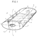
- Figure 1 is a perspective view of a class IV flextensional transducer as it may exist to date.
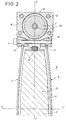
- Figure 2 is a sectional view of a class V flextensional transducer produced in accordance with the present invention.
- the transducers shown are therefore by way of example for FIG. 1 a type IV transducer, and for FIG. 2 a type V transducer: they comprise, in a known manner. one or more electro-acoustic motors 1, placed along the same plane defined by the axes xx '/ yy', inside which relates to FIG. 1 and in the peripheral ring with regard to FIG. 2 of a flexible envelope 5, of which they are integral, at least at one of their ends by any assembly device, either in FIG. 1 for the parts or masses of connection 2, and in FIG.
- said electro-acoustic motors 1 and their counter-masses 9 transmit their vibrations to said flexible envelope 5 which is in contact with said external liquid 4, constituting the surface for emitting acoustic waves; said flattened ellipsoid shape of said surface makes it possible to amplify the amplitude of the vibrations and to obtain a range of waves of very low frequencies.
- the transducer of type IV shown, has a flexible envelope 5 of elongated cylinder shape, the cross section of which is in the shape of an ellipse, and the electro-acoustic motors 1 represented in number of three in this example, are parallel to each other. along an axis yy 'and their axes are placed in transverse planes perpendicular to the generatrices of the cylinder along the axis xx' of the envelope 5.
- each motor is mechanically and acoustically coupled by the connecting pieces 2 with the cylindrical shell 5, but in other cases, in particular when it is a class II transducer according to the shape of the shell thereof, said motors 1 may be integral only at one of their ends, the other being able to bear on a central pillar acting as counterweight.
- one of said end flanges 3 comprises at least one opening 6, the dimensions of which, according to the systems existing to date, associated with the characteristics of the casing 5, are determined so that by coupling the elasticity of this envelope with the mass of the liquid 4 located in said opening 6, the Helmholtz frequency of the cavity 7 is close to the fundamental frequency of the vibrations of the assembly formed by said electro-acoustic motors 1 and of any element associated with these, such as the connecting pieces 2.
- such a type IV transducer according to FIG. 1 could be fitted according to the present invention with an internal baffle 15, as shown in the example in FIG. 2, and connected to the central part, for example electro-acoustic motors 1, since such a baffle must not be able to be driven by the external envelope 5 and can vibrate with it.
- the latter comprises a motor ring 13 formed of a crown of several ceramic pillars or electro-acoustic motors 1 in number for example of eight, and associated with counter-masses 9, connected by various assembly screws 8 allowing, the continuity of the peripheral driving crown 13.
- central rods 18 ensure the prestressing of the ceramic pillars 1 .
- this crown motor element is not further specified in the context of the present description, since it is not an object of the invention, and there are already today various transducer systems using such a provision.
- the casing 5 forming said vibrating shell is composed of two convex discs connected at their periphery by at least one part 10 in the form of a torus, so that these two convex discs 5 are just supported and immobilized at their periphery each in a groove 17 of the part 10.
- the two convex discs can be turned both outwards, but also and possibly both inwards or one outwards and the other towards inside, but preferably, the orientation of the convexity of the two discs towards the outside will be chosen as shown in the figure.
- Each of the grooves 17 is in fact carried by elements arranged in a crown, and constituting the parts 10, independent of each other for each of the two opposite and convex discs, and connected two by two, on either side of the plane in which are the acoustic motors 1, by any means 11 for adjusting relative distance; which crowns of parts 10 each have a conical surface 12, cooperating with a surface of the same shape, carried by another peripheral continuous outer ring 13, so that the action of bringing together elements of the part 10 by the means 11 , decreases the length of the circumference of the grooves 17 by pinching effect and provides prestressing of the discs 5.
- the enclosure comprising the envelope 5, thus constituted comprises any opening, not shown in this section of figure, but being able to let said liquid 4 penetrate in all the interior cavity 7 delimited by the envelope, such as for example an opening between two motors 1 in the outer ring 13.
- a baffle 15 of cellular material resistant to immersion pressure occupies most of the volume of the cavity 7, the external surface of which is at a constant distance 14 from that of the envelope 5, and which is integral with the device d assembly 8 of the electro-acoustic motors 1 in a ring 13.
- This assembly can be carried out by elastic studs 16 spaced apart on the rear structure of the transducers 1, such as that formed by the supports and the counter-masses 9 over the entire periphery of this outer crown 13.
- the elastic material constituting said studs 16 has elastic characteristics such that its radial speed of displacement in compression is less than ten times that of electro-acoustic motors.
- said distance 14 separating the surfaces of the baffle 15 from the casing 5 and filled with liquid 4 is between 3 to 6 mm.
- the acoustic and specific impedance again called characteristic impedance of the material which constitutes it, and defined by the product of its density rm and the speed Cm of wave propagation in the material, ie such that: (rm x Cm) of the material ⁇ 0.7 of (ro x Co) water.
Landscapes
- Physics & Mathematics (AREA)
- Engineering & Computer Science (AREA)
- Acoustics & Sound (AREA)
- Multimedia (AREA)
- Transducers For Ultrasonic Waves (AREA)
- Piezo-Electric Transducers For Audible Bands (AREA)
- Apparatuses For Generation Of Mechanical Vibrations (AREA)
Applications Claiming Priority (2)
| Application Number | Priority Date | Filing Date | Title |
|---|---|---|---|
| FR9314503 | 1993-12-03 | ||
| FR9314503A FR2713430B1 (fr) | 1993-12-03 | 1993-12-03 | Procédé d'émission d'ondes acoustiques très basses fréquences à forte puissance, et transducteurs correspondants. |
Publications (2)
| Publication Number | Publication Date |
|---|---|
| EP0657868A1 true EP0657868A1 (de) | 1995-06-14 |
| EP0657868B1 EP0657868B1 (de) | 1999-08-11 |
Family
ID=9453523
Family Applications (1)
| Application Number | Title | Priority Date | Filing Date |
|---|---|---|---|
| EP94402749A Expired - Lifetime EP0657868B1 (de) | 1993-12-03 | 1994-12-01 | Verfahren und Wandler zum Aussenden von sehr niederfrequenten akustischen Wellen mit grosser Leistung |
Country Status (7)
| Country | Link |
|---|---|
| US (1) | US5469406A (de) |
| EP (1) | EP0657868B1 (de) |
| CA (1) | CA2137187C (de) |
| DE (1) | DE69420019T2 (de) |
| DK (1) | DK0657868T3 (de) |
| ES (1) | ES2135552T3 (de) |
| FR (1) | FR2713430B1 (de) |
Cited By (1)
| Publication number | Priority date | Publication date | Assignee | Title |
|---|---|---|---|---|
| EP0716407A3 (de) * | 1994-12-10 | 1996-07-17 | Stn Atlas Elektronik Gmbh |
Families Citing this family (2)
| Publication number | Priority date | Publication date | Assignee | Title |
|---|---|---|---|---|
| US7081699B2 (en) * | 2003-03-31 | 2006-07-25 | The Penn State Research Foundation | Thermoacoustic piezoelectric generator |
| AU2021211657B2 (en) | 2020-01-21 | 2026-04-09 | Adbm Corp. | Simultaneously attenuating high-frequencies and amplifying low-frequencies of underwater sounds |
Citations (2)
| Publication number | Priority date | Publication date | Assignee | Title |
|---|---|---|---|---|
| EP0363032A2 (de) * | 1988-10-04 | 1990-04-11 | British Aerospace Public Limited Company | Flexeinsgespannter Wandler |
| EP0421613A2 (de) * | 1989-10-06 | 1991-04-10 | British Aerospace Public Limited Company | Schallerzeugender Wandler |
Family Cites Families (9)
| Publication number | Priority date | Publication date | Assignee | Title |
|---|---|---|---|---|
| US4135142A (en) * | 1977-08-08 | 1979-01-16 | The United States Of America As Represented By The Secretary Of The Navy | Non-linear acoustic transducer |
| CA1171950A (en) * | 1981-12-22 | 1984-07-31 | Garfield W. Mcmahon | Underwater transducer with depth compensation |
| US4853905A (en) * | 1988-02-05 | 1989-08-01 | Conoco Inc. | Seal for marine seismic source |
| FR2634292B1 (fr) * | 1988-07-15 | 1990-10-19 | Grosso Gilles | Procede et dispositifs pour maintenir le gaz contenu dans une enceinte immergee en equilibre de pression avec l'exterieur |
| US5223570A (en) * | 1990-02-07 | 1993-06-29 | Basf Corporation | Method for the preparation of graft polymer dispersions having broad particle size distribution without wildly fluctuating viscosities |
| FR2665814B1 (fr) * | 1990-08-10 | 1993-06-11 | Thomson Csf | Transducteur electroacoustique destine a etre immerge et comportant un systeme de compensation automatique de la pression d'immersion. |
| FR2671927B1 (fr) * | 1991-01-22 | 1995-10-06 | France Etat Armement | Transducteurs electro-acoustiques directifs et procedes et dispositifs de fabrication. |
| US5268879A (en) * | 1991-12-03 | 1993-12-07 | Raytheon Company | Electro-acostic transducers |
| US5224074A (en) * | 1992-07-08 | 1993-06-29 | The United States Of America As Represented By The Secretary Of The Navy | Sonobuoy for forming virtual vertical sensing arrays |
-
1993
- 1993-12-03 FR FR9314503A patent/FR2713430B1/fr not_active Expired - Fee Related
-
1994
- 1994-12-01 DE DE69420019T patent/DE69420019T2/de not_active Expired - Fee Related
- 1994-12-01 ES ES94402749T patent/ES2135552T3/es not_active Expired - Lifetime
- 1994-12-01 EP EP94402749A patent/EP0657868B1/de not_active Expired - Lifetime
- 1994-12-01 US US08/352,125 patent/US5469406A/en not_active Expired - Fee Related
- 1994-12-01 DK DK94402749T patent/DK0657868T3/da active
- 1994-12-02 CA CA002137187A patent/CA2137187C/fr not_active Expired - Fee Related
Patent Citations (2)
| Publication number | Priority date | Publication date | Assignee | Title |
|---|---|---|---|---|
| EP0363032A2 (de) * | 1988-10-04 | 1990-04-11 | British Aerospace Public Limited Company | Flexeinsgespannter Wandler |
| EP0421613A2 (de) * | 1989-10-06 | 1991-04-10 | British Aerospace Public Limited Company | Schallerzeugender Wandler |
Cited By (1)
| Publication number | Priority date | Publication date | Assignee | Title |
|---|---|---|---|---|
| EP0716407A3 (de) * | 1994-12-10 | 1996-07-17 | Stn Atlas Elektronik Gmbh |
Also Published As
| Publication number | Publication date |
|---|---|
| ES2135552T3 (es) | 1999-11-01 |
| FR2713430A1 (fr) | 1995-06-09 |
| CA2137187A1 (fr) | 1995-06-04 |
| DK0657868T3 (da) | 2000-03-06 |
| CA2137187C (fr) | 2003-10-21 |
| DE69420019T2 (de) | 1999-12-09 |
| US5469406A (en) | 1995-11-21 |
| EP0657868B1 (de) | 1999-08-11 |
| DE69420019D1 (de) | 1999-09-16 |
| FR2713430B1 (fr) | 1996-03-08 |
Similar Documents
| Publication | Publication Date | Title |
|---|---|---|
| EP2670536B1 (de) | Elektroakustischer niederfrequenzwandler und verfahren zur erzeugung von schallwellen | |
| EP0684084B1 (de) | Verfahren und Wandler zum Ausstrahlen von Breitband- und Niederfrequenz-Schallwellen in unbegrenzter Tauchtiefe | |
| EP0002161A2 (de) | Piezoelektrischer Übertrager und Verfahren zu seiner Herstellung | |
| CH667356A5 (fr) | Transducteur de vibration cylindrique du type a cintrage. | |
| EP2858760A2 (de) | Vorrichtung und verfahren zum fokussieren von impulsen | |
| FR2557704A1 (fr) | Source sismique marine | |
| FR2665998A1 (fr) | Procedes et transducteurs electro-acoustiques pour emettre des ondes acoustiques a basse frequence dans un liquide. | |
| EP0728535B1 (de) | Verfahren und Vorrichtung zur Verminderung der Resonanzfrequenz von Hohlräumen von Unterwasserwandlern | |
| CA2137187C (fr) | Procede d'emission d'ondes acoustiques tres basses frequences a forte puissance, et transducteurs correspondants | |
| EP3677051B1 (de) | Wasserschallgehäuse | |
| FR2609337A1 (fr) | Transducteur electroacoustique a decharges electriques disruptives pour analyse de sondages | |
| EP0656232A1 (de) | Verfahren zum Hochleistungsemission von akustischen Wellen und damit übereinstimmende Wandlerhorne | |
| CA2109466C (fr) | Procede et transducteurs pour emettre des ondes acoustiques basse frequence dans un liquide en immersion illimitee | |
| CH710166A2 (fr) | Agencement à membranes de rayonnement acoustique pour une montre musicale ou à sonnerie. | |
| EP0114764B1 (de) | Vorrichtung zur Reflexion von akustischen Wellen | |
| FR2697710A1 (fr) | Procédé et transducteur pour émettre des ondes acoustiques de très basses fréquences, dans un liquide en immersion illimitée. | |
| EP0881001B1 (de) | Elektrodynamischer Wandler für Unterwasser-Akustik | |
| CA2109465C (fr) | Dispositif d'etancheite de moteurs electro-acoustiques | |
| EP0728534B1 (de) | Verfahren und in einer Flussigkeit versekter Handler mit leichten Strahler zum Aussenden von niederfrequenten akustischen Wellen | |
| FR2664782A1 (fr) | Enceinte acoustique omnidirectionnelle. | |
| CA2038737C (fr) | Procedes et transducteurs electro-acoustiques pour emettre des ondes acoustiques a basse frequence dans un liquide | |
| EP0728533A1 (de) | Verfahren und Wandler zum Aussenden von akustischen Wellen in einer Flüssigkeit mit einer betonten Richtcharakteristik bei Niederfrequenzen | |
| FR2720585A1 (fr) | Transducteur électro acoustique antenne sonar ouverts. | |
| FR2664868A1 (fr) | Revetement anechouide, en particulier pour coques de navires et de sous-marins. | |
| EP2700247A1 (de) | Vorrichtung zum aussenden von schallwellen |
Legal Events
| Date | Code | Title | Description |
|---|---|---|---|
| PUAI | Public reference made under article 153(3) epc to a published international application that has entered the european phase |
Free format text: ORIGINAL CODE: 0009012 |
|
| 17P | Request for examination filed |
Effective date: 19941227 |
|
| AK | Designated contracting states |
Kind code of ref document: A1 Designated state(s): DE DK ES GB IT NL SE |
|
| GRAG | Despatch of communication of intention to grant |
Free format text: ORIGINAL CODE: EPIDOS AGRA |
|
| GRAG | Despatch of communication of intention to grant |
Free format text: ORIGINAL CODE: EPIDOS AGRA |
|
| GRAH | Despatch of communication of intention to grant a patent |
Free format text: ORIGINAL CODE: EPIDOS IGRA |
|
| 17Q | First examination report despatched |
Effective date: 19981209 |
|
| GRAH | Despatch of communication of intention to grant a patent |
Free format text: ORIGINAL CODE: EPIDOS IGRA |
|
| GRAA | (expected) grant |
Free format text: ORIGINAL CODE: 0009210 |
|
| AK | Designated contracting states |
Kind code of ref document: B1 Designated state(s): DE DK ES GB IT NL SE |
|
| ITF | It: translation for a ep patent filed | ||
| GBT | Gb: translation of ep patent filed (gb section 77(6)(a)/1977) |
Effective date: 19990812 |
|
| REF | Corresponds to: |
Ref document number: 69420019 Country of ref document: DE Date of ref document: 19990916 |
|
| REG | Reference to a national code |
Ref country code: ES Ref legal event code: FG2A Ref document number: 2135552 Country of ref document: ES Kind code of ref document: T3 |
|
| REG | Reference to a national code |
Ref country code: DK Ref legal event code: T3 |
|
| PLBE | No opposition filed within time limit |
Free format text: ORIGINAL CODE: 0009261 |
|
| STAA | Information on the status of an ep patent application or granted ep patent |
Free format text: STATUS: NO OPPOSITION FILED WITHIN TIME LIMIT |
|
| 26N | No opposition filed | ||
| REG | Reference to a national code |
Ref country code: GB Ref legal event code: IF02 |
|
| PGFP | Annual fee paid to national office [announced via postgrant information from national office to epo] |
Ref country code: SE Payment date: 20031031 Year of fee payment: 10 |
|
| PGFP | Annual fee paid to national office [announced via postgrant information from national office to epo] |
Ref country code: GB Payment date: 20031203 Year of fee payment: 10 |
|
| PGFP | Annual fee paid to national office [announced via postgrant information from national office to epo] |
Ref country code: ES Payment date: 20031230 Year of fee payment: 10 |
|
| PGFP | Annual fee paid to national office [announced via postgrant information from national office to epo] |
Ref country code: NL Payment date: 20031231 Year of fee payment: 10 |
|
| PGFP | Annual fee paid to national office [announced via postgrant information from national office to epo] |
Ref country code: DE Payment date: 20040216 Year of fee payment: 10 |
|
| PGFP | Annual fee paid to national office [announced via postgrant information from national office to epo] |
Ref country code: DK Payment date: 20041026 Year of fee payment: 11 |
|
| PG25 | Lapsed in a contracting state [announced via postgrant information from national office to epo] |
Ref country code: GB Free format text: LAPSE BECAUSE OF NON-PAYMENT OF DUE FEES Effective date: 20041201 |
|
| PG25 | Lapsed in a contracting state [announced via postgrant information from national office to epo] |
Ref country code: SE Free format text: LAPSE BECAUSE OF NON-PAYMENT OF DUE FEES Effective date: 20041202 Ref country code: ES Free format text: LAPSE BECAUSE OF NON-PAYMENT OF DUE FEES Effective date: 20041202 |
|
| PG25 | Lapsed in a contracting state [announced via postgrant information from national office to epo] |
Ref country code: NL Free format text: LAPSE BECAUSE OF NON-PAYMENT OF DUE FEES Effective date: 20050701 Ref country code: DE Free format text: LAPSE BECAUSE OF NON-PAYMENT OF DUE FEES Effective date: 20050701 |
|
| GBPC | Gb: european patent ceased through non-payment of renewal fee |
Effective date: 20041201 |
|
| EUG | Se: european patent has lapsed | ||
| NLV4 | Nl: lapsed or anulled due to non-payment of the annual fee |
Effective date: 20050701 |
|
| PG25 | Lapsed in a contracting state [announced via postgrant information from national office to epo] |
Ref country code: IT Free format text: LAPSE BECAUSE OF NON-PAYMENT OF DUE FEES;WARNING: LAPSES OF ITALIAN PATENTS WITH EFFECTIVE DATE BEFORE 2007 MAY HAVE OCCURRED AT ANY TIME BEFORE 2007. THE CORRECT EFFECTIVE DATE MAY BE DIFFERENT FROM THE ONE RECORDED. Effective date: 20051201 |
|
| PG25 | Lapsed in a contracting state [announced via postgrant information from national office to epo] |
Ref country code: DK Free format text: LAPSE BECAUSE OF NON-PAYMENT OF DUE FEES Effective date: 20060102 |
|
| REG | Reference to a national code |
Ref country code: ES Ref legal event code: FD2A Effective date: 20041202 |
|
| REG | Reference to a national code |
Ref country code: DK Ref legal event code: EBP |