EP0684084B1 - Verfahren und Wandler zum Ausstrahlen von Breitband- und Niederfrequenz-Schallwellen in unbegrenzter Tauchtiefe - Google Patents
Verfahren und Wandler zum Ausstrahlen von Breitband- und Niederfrequenz-Schallwellen in unbegrenzter Tauchtiefe Download PDFInfo
- Publication number
- EP0684084B1 EP0684084B1 EP95401229A EP95401229A EP0684084B1 EP 0684084 B1 EP0684084 B1 EP 0684084B1 EP 95401229 A EP95401229 A EP 95401229A EP 95401229 A EP95401229 A EP 95401229A EP 0684084 B1 EP0684084 B1 EP 0684084B1
- Authority
- EP
- European Patent Office
- Prior art keywords
- liquid
- transducer
- cavity
- housing
- opening
- Prior art date
- Legal status (The legal status is an assumption and is not a legal conclusion. Google has not performed a legal analysis and makes no representation as to the accuracy of the status listed.)
- Expired - Lifetime
Links
Images
Classifications
-
- B—PERFORMING OPERATIONS; TRANSPORTING
- B06—GENERATING OR TRANSMITTING MECHANICAL VIBRATIONS IN GENERAL
- B06B—METHODS OR APPARATUS FOR GENERATING OR TRANSMITTING MECHANICAL VIBRATIONS OF INFRASONIC, SONIC, OR ULTRASONIC FREQUENCY, e.g. FOR PERFORMING MECHANICAL WORK IN GENERAL
- B06B1/00—Methods or apparatus for generating mechanical vibrations of infrasonic, sonic, or ultrasonic frequency
- B06B1/02—Methods or apparatus for generating mechanical vibrations of infrasonic, sonic, or ultrasonic frequency making use of electrical energy
- B06B1/06—Methods or apparatus for generating mechanical vibrations of infrasonic, sonic, or ultrasonic frequency making use of electrical energy operating with piezoelectric effect or with electrostriction
- B06B1/0607—Methods or apparatus for generating mechanical vibrations of infrasonic, sonic, or ultrasonic frequency making use of electrical energy operating with piezoelectric effect or with electrostriction using multiple elements
- B06B1/0611—Methods or apparatus for generating mechanical vibrations of infrasonic, sonic, or ultrasonic frequency making use of electrical energy operating with piezoelectric effect or with electrostriction using multiple elements in a pile
- B06B1/0618—Methods or apparatus for generating mechanical vibrations of infrasonic, sonic, or ultrasonic frequency making use of electrical energy operating with piezoelectric effect or with electrostriction using multiple elements in a pile of piezo- and non-piezoelectric elements, e.g. 'Tonpilz'
Definitions
- the subject of the present invention is a method and transducer for transmitting wideband and low frequency acoustic waves in immersion depth unlimited.
- the technical sector of the invention is that of the manufacture of transducers electro-acoustic for the emission of acoustic waves in a liquid.
- the main application of the invention is the possibility of emitting waves acoustic at low frequencies, at very great depth and in a band of fairly wide frequencies.
- immersible electro-acoustic transducers and particular piezoelectric, some of which for which the present invention is preferably intended for, but not limited to, include a cylindrical housing rigid, hollow and open at its two axial ends, and inside which are arranged coaxially therewith, two identical electro-acoustic motors, placed on either side of a central counterweight, and whose opposite ends are surrounded by a pavilion.
- Said electro-acoustic motors can be produced by two stacks of aligned piezoelectric plates.
- the external faces of two pavilions are located in the plane of the axial ends of the case, so that they are in contact with the liquid, in which the case is immersed, and the perimeter external of these pavilions comes closest to the edge of the open axial ends said housing.
- these external faces emit acoustic waves into the liquid when the electro-acoustic motors are electronically excited: these transducers are used in particular to emit acoustic waves into water low frequency in a specific direction.
- a third category of solution makes it possible to overcome both the mechanical and / or pneumatic problems of the first solution and the strip corresponding frequency, as well as problems with falling water levels of emission and shift towards the high frequencies of the second solution: this category is described in the FR patent application. 2.665.998 OF 05 May 1988 registered by the French State General Delegate for Armaments: it consists in using a rigid case, but not waterproof, making it possible to delimit a cavity filled with ambient liquid behind the pavilions, in which elastic tubes are placed closed, sealed and filled with gas, and such as the Helmholtz resonant frequency of the cavity is close to the fundamental frequency of the axial vibrations of the vibrating assembly; we then obtain a good fairly wide frequency range two peaks corresponding to natural frequencies, one related to mechanical vibrations from the transducer, and the other to the cavity, and with attenuation at most 5dB between the two peaks.
- a fourth category of solution allowing not to imitate depth while keeping a fairly wide and low frequency band, and without complexity of construction, was developed with a housing made of material resistant to elastic pressure, and having an opening, the dimensions of which are determined so that by coupling the elasticity of the housing with the mass of the liquid located in this opening, the Helmholtz frequency of the cavity of the case is close to the fundamental frequency of vibrations of the whole transducer:
- this category solution was especially developed for transducers such as those described in introduction to this description, comprising a cylindrical, rigid housing, and hollow open at its two axial ends, and inside which are arranged coaxially with it, two identical electroacoustic motors, placed on the side and on the other side of a central counter-mass, and whose opposite ends are surrounded a pavilion.
- EP-A-0 596 763 also discloses a transducer to emit low frequency acoustic waves into a liquid in unlimited immersion, "double Tonpilz" type equipped with a waterproof case and a peripheral opening, whose dimensions are determined as well as characteristics of the case, so that by coupling elasticity of this case with the mass of liquid located in said opening, the Helmholtz frequency of the cavity determined by the case, or close to the frequency fundamental of the axial vibrations of the set by electro-acoustic motors.
- the problem is therefore to be able to produce acoustic transducers low frequencies in a liquid, without limitation of depth, without weighing down or increase the volume and / or the complexity of production of these transducers, and with fairly wide transmission frequency bandwidth, with no significant drop level attenuation over the entire width of this strip.
- At least one bladder is filled with a more compressible liquid than liquid; there is provided in said housing at least one opening allowing the passage of said bladder thus filled; said bladder is slid into said cavity by said opening, so that all or at least part of the volume of said cavity is occupied by at least said bladder.
- transducer to emit low frequency acoustic waves in a liquid as defined above is comprising at least one electroacoustic motor vibrating any wall of emission of said waves, and a hollow box enclosing said motor, and delimiting, inter alia, with said vibrating wall, a cavity, which transducer comprises at at least one opening communicating said cavity with the surrounding environment, at least one flexible bladder occupying all or at least part of the entire volume of said cavity, which bladder being filled with a more compressible liquid that said liquid.
- the compressibility of the liquid is less than 10 9 N / m 2
- the viscosity of the liquid is at most equal to that of water, which has the value 10 -6 m 2 / second: preferably, the viscosity of the liquid is less than 6.5 x 10⁻⁷ m 2 / second.
- silicone oil whose density is greater than 920 kg / m 3 , and the speed of propagation of the sound in this oil is greater than 1010 m / second, corresponding to a compressibility module greater than 0.954 x 10 9 N / m 2 .
- such a method and transducer according to the invention allow in particular to combine the advantages mentioned above in the third and fourth category of solutions analyzed in the introduction, namely: that of a cavity filled with ambient liquid, in which elastic tubes are placed closed, allowing to obtain two resonance peaks determining a range of bands fairly wide frequencies, without loss or attenuation of more than 5dB between these two peaks ; and the solution of an opening of determined dimensions so that the frequency Helmholtz of the cavity is close to that fundamental of the vibrations of the whole mechanical, which makes it possible to go down in frequency, while resisting pressures unlimited.
- the characteristics of the present invention are applicable to any type of transducers, having a cavity in communication with the ambient medium, such as those described above and taken as examples in the figure below, but also in flextensional type transducers: one can cite for example for this type of transducer the patent GN-8823245 of J.R.OSWIN which, in the cavity filled with water a classic flextensional transducer, adds a Helmholtz resonator; of compliant tubes can be inserted to increase compliance and therefore go down in frequency.
- the interest of the present invention is maximum whenever it is desired to reduce loss of efficiency and frequency attenuation between two resonance peaks, one of which is linked to the mechanical resonance of the assembly, and the other to that of a cavity.
- n / A not at all the same function as those used in the current prior art, which is actually either a transmission and pressure compensation fluid only external, i.e. a coolant, and whose choice, neither the arrangement, nor the criteria had not yet been determined to solve the problem posed in the present invention.
- transducers according to the present invention is to be able to be used in the context of acoustic ocean tomography, to which must be able to immerse the transducers up to 2,000 meters of immersion on the one hand, and on the other hand, being able to transmit in frequency bands wide, and at the lowest possible frequencies, to have the most propagation far from the air: a publication of the journal "For Science" No.
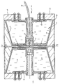
- the single figure is a sectional view of a particular type of transducer, equipped with the characteristic elements of the invention.
- the transducer as shown in section in this figure, comprises of known manner, two electroacoustic motors 1, aligned along an axis xx ', placed on either side of a central counterweight 2, and coaxially inside a 5 cylindrical housing, covering all of said motors 1 to the roof 3 end thereof; the cavity 7 thus delimited by the rear of said pavilions and the housing is in communication with the external immersion liquid 4, thanks to openings 6 made in this housing 5.
- Said electroacoustic motors 1 can be of the piezoelectric type, but also magnetostrictive cylinders surrounded by an excitation coil.
- Such electroacoustic double motor transducers are also said to be double Tonpilz.
- said electroacoustic motors 1 and the counterweight intermediate 2 are shown assembled assembled, thanks to different pieces of link 11, themselves connected to different fasteners 12, connecting said motor electroacoustic or box 5, thanks to any fixing means, and allowing freedom displacement of the pavilions 3 end relative to said housing, but determining an almost closed internal cavity 7 between the respective edges 13 of said pavilions and said housing.
- the power of said electroacoustic motors 1 is supplied by any cable supply 10, fixed to said connecting pieces 11 by an electrical connector 14.
- the main feature of the process of the present invention and the transducer according to this, is that it comprises at least one flexible bladder 8, occupying at least part if not all of the entire volume of said cavity 7, and filled of a liquid 9 which is more compressible than the ambient liquid 4.
- the liquid 9 occupying the volumes delimited by the skin of said bladders 8, must fill at best and preferably practically the entire cavity, because its volume must in fact be greater than that of compliant tubes such as those described in the FR patent application. 2.665.998 of 05 May 1988, so as to have compressibility characteristics equivalent to that of said tubes as used at today in this type of transducer; indeed, the drop in emission level of frequencies in the range defined between the two peaks considered above, is linked precisely to the elasticity of the volume of this liquid included in the cavity, and whose role is also that of the compliant tubes of the patent cited above.
- the compressibility of said liquid must in fact be less than 10 9 N / m 2 , defined by the product of its density f with the square of the speed of propagation of sound in this liquid C f .
- volume of cavity 7 volume of liquid 9 + volume of residual water that may exist in cavity 7 .
- overall system compliance (liquid volume / f x C f 2 liquid) + (water volume / 2.22 x 10 9 ).
- said opening 6 is such that its dimensions are determined so that by coupling of the elasticity of the housing 5 with the mass of the liquid located in this opening 6, the Helmholtz frequency of the cavity 7 of the case is close to the frequency fundamental vibration of the transducer assembly.
- a transducer comprises two electroacoustic motors 1 aligned on an axis xx 'placed on the side and on the other side of a central counterweight 2 and coaxially inside said housing 5 cylindrical and hollow, covering all of said motors 1 up to the vibrating walls 3 forming an end flag thereof, which opening 6 is made in said housing in the vicinity of its median plane.
- said edges of said aperture 6 are each associated with a crown of pressure-resistant material and forming an integral part of the housing to which they are integral; said crown is not shown in the figure.
Landscapes
- Engineering & Computer Science (AREA)
- Mechanical Engineering (AREA)
- Transducers For Ultrasonic Waves (AREA)
- Piezo-Electric Transducers For Audible Bands (AREA)
Claims (10)
- Verfahren zum Senden von niederfrequenten Schallwellen in einer Flüssigkeit (4) unter Einsatz eines Wandlers, bestehend aus mindestens einem elektroakustischen Antrieb (1), welcher jede Sendewand (3) der besagten Wellen in Schwingung versetzt, und einem hohlen Gehäuse (5), welches den besagten Antrieb (1) umrahmt und u.a. mit der besagten Schwingwand (3) einen Hohlraum (7) begrenzt, dadurch gekennzeichnet, daß:das besagte Gehäuse (5) mit mindestens einer Öffnung (6) ausgestattet ist, über welche der Hohlraum (7) mit dem Umgebungsmedium (5) in Kontakt steht;in mindestens einem Teil des Volumens des besagten Hohlraums (7) mindestens eine elastische Blase (8) angeordnet wird;diese Blase (8) mit einer Flüssigkeit (9) gefüllt wird, deren Komressibilität höher ist als die der Umgebungsflüssigkeit (4).
- Verfahren zum Senden von niederfrequenten Schallwellen in einer Flüssigkeit (4) unter Einsatz eines Wandlers, bestehend aus mindestens einem elektroakustischen Antrieb (1), welcher jede Sendewand (3) der besagten Wellen in Schwingung versetzt, und einem hohlen Gehäuse (5), welches den besagten Antrieb (1) umrahmt und u.a. mit der besagten Schwingwand (3) einen Hohlraum (7) begrenzt, dadurch gekennzeichnet, daß:mindestens eine Blase mit einer Flüssigkeit (9) gefüllt wird, deren Komressibilität höher ist als die der Umgebungsflüssigkeit (4).das besagte Gehäuse (5) mit mindestens einer Öffnung ausgestattet ist, welche das Durchführen der besagten, so gefüllten Blase (8) ermöglicht;die besagte Blase (8) durch die besagte Öffnung (6) in den Hohlraum (7) eingeführt wird, so daß mindestens ein Teil des Volumens des besagten Hohlraums (7) von mindestens der besagten Blase (8) belegt ist.
- Wandler zum Senden von niederfrequenten Schallwellen in einer Flüssigkeit (4), bestehend aus mindestens einem elektroakustischen Antrieb (1), welcher jede Sendewand (3) der besagten Wellen in Schwingung versetzt, und einem hohlen Gehäuse (5), welches den besagten Antrieb (1) umrahmt und u.a. mit der besagten Schwingwand (3) einen Hohlraum (7) abgrenzt, dadurch gekennzeichnet, daß er mindestens eine Öffnung (6), über welche der besagte Hohlraum (7) mit dem Umgebungsmedium (4) in Kontakt steht, und mindestens eine elastische Blase (8), welche mindestens einen Teil des Volumens des besagten Hohlraums (7) belegt und mit einer Flüssigkeit (9) gefüllt ist, deren Kompressibilität höher ist als die der besagten Umgebungsflüssigkeit (4), enthält.
- Wandler zum Senden von Schallwellen gemäß Patentanspruch 3, dadurch gekennzeichnet, daß die Kompressibilität der besagten Flüssigkeit (9) unter 109 N/m2 liegt.
- Wandler gemäß irgendeinem der Patentansprüche 3 oder 4, dadurch gekennzeichnet, daß die Viskosität der besagten Flüssigkeit (9) höchstens mit der Viskosität des Wassers gleichwertig ist.
- Wandler gemäß Patentansprüche 5, dadurch gekennzeichnet, daß die besagte Viskosität der Flüssigkeit unter 6,5 x 10⁻⁷ m2/Sekunde liegt.
- Wandler gemäß irgendeinem der Patentansprüche 3 bis 6, dadurch gekennzeichnet, daß es sich bei der besagten Flüssigkeit um eine total fluorisierte organische Verbindung vom Typ C8F18 handelt.
- Wandler gemäß irgendeinem der Patentansprüche 3 bis 7, dadurch gekennzeichnet, daß die Abmessungen der besagten Öffnung (6) so festgelegt sind, daß die Helmholtzsche Frequenz des Hohlraums (7) des Gehäuses durch die Kupplung der Elastizität des Gehäuses (5) mit der Masse der sich in dieser Öffnung (6) befindlichen Flüssigkeit (4) and die Grundfrequenz der Schwingungen des gesamten Wandlers angrenzt.
- Wandler gemäß irgendeinem der Patentansprüche 3 bis 8, dadurch gekennzeichnet, daß er zwei elektroakustische Antriebe (1) enthält, welche auf einer Achse (xx') beiderseits einer mittleren Gegenmasse (2) und koaxial im Inneren des besagten zylinderförmigen und hohlen Gehäuses (5) angeordnet sind, wobei das Gehäuse die besagten Antriebe (1) bis zu den schwingenden Wänden (3), welche deren Endkegel bilden, abdeckt und die Öffnung (6) im besagten Gehäuse in unmittelbarer Nähe seiner Mittelebene angebracht ist.
- Wandler gemäß den Patentansprüche 8 und 9, dadurch gekennzeichnet, daß die besagte Öffnung (6) peripher und kreisförmig ist und deren besagte Kanten jeweils mit einer Einfassung aus einem druckwiderstandsfähigen Material verbunden sind, welche integraler Bestandteil des Gehäuses (5) und mit diesem fest verbunden sind.
Applications Claiming Priority (2)
| Application Number | Priority Date | Filing Date | Title |
|---|---|---|---|
| FR9406439A FR2720589B1 (fr) | 1994-05-27 | 1994-05-27 | Procédé et transducteur pour émettre des ondes acoustiques à larges bandes et basses fréquences en profondeur d'immersion illimitée. |
| FR9406439 | 1994-05-27 |
Publications (2)
| Publication Number | Publication Date |
|---|---|
| EP0684084A1 EP0684084A1 (de) | 1995-11-29 |
| EP0684084B1 true EP0684084B1 (de) | 1998-11-25 |
Family
ID=9463568
Family Applications (1)
| Application Number | Title | Priority Date | Filing Date |
|---|---|---|---|
| EP95401229A Expired - Lifetime EP0684084B1 (de) | 1994-05-27 | 1995-05-26 | Verfahren und Wandler zum Ausstrahlen von Breitband- und Niederfrequenz-Schallwellen in unbegrenzter Tauchtiefe |
Country Status (7)
| Country | Link |
|---|---|
| US (1) | US5579287A (de) |
| EP (1) | EP0684084B1 (de) |
| CA (1) | CA2150297C (de) |
| DE (1) | DE69506169T2 (de) |
| DK (1) | DK0684084T3 (de) |
| ES (1) | ES2124507T3 (de) |
| FR (1) | FR2720589B1 (de) |
Families Citing this family (14)
| Publication number | Priority date | Publication date | Assignee | Title |
|---|---|---|---|---|
| FR2818754B1 (fr) * | 2000-12-21 | 2004-06-18 | Inst Francais Du Petrole | Dispositif pour engendrer des ondes elastiques focalisees dans un milieu materiel tel que le sous-sol, et methode pour sa mise en oeuvre |
| DE50204478D1 (de) * | 2001-04-06 | 2006-02-16 | Oce Printing Systems Gmbh | Verfahren, system und computerprogramm zum erstellen eines elektronischen dokuments aus gerasterten bilddaten |
| DE10345533A1 (de) * | 2003-09-30 | 2005-05-04 | Fraunhofer Ges Forschung | Ultraschallwandler zum Betrieb in einem unter erhöhtem Druck stehenden Medium |
| FR2971112B1 (fr) * | 2011-02-01 | 2014-01-03 | Ixblue | Transducteur electro-acoustique basse frequence et procede de generation d'ondes acoustiques. |
| GB2508206B (en) * | 2012-11-23 | 2017-06-28 | Thales Holdings Uk Plc | A transducer for a locator beacon and an underwater locator beacon |
| US9995834B2 (en) * | 2013-05-07 | 2018-06-12 | Pgs Geophysical As | Variable mass load marine vibrator |
| US10488542B2 (en) | 2014-12-02 | 2019-11-26 | Pgs Geophysical As | Use of external driver to energize a seismic source |
| US20160202365A1 (en) * | 2015-01-08 | 2016-07-14 | Pgs Geophysical As | Compliance chamber with linear motor for marine acoustic vibrators |
| FR3042134B1 (fr) | 2015-10-09 | 2020-10-09 | Ixblue | Dispositif d'emission/reception acoustique sous-marine a large bande |
| US12345154B2 (en) | 2022-09-14 | 2025-07-01 | Saudi Arabian Oil Company | Untethered logging devices and related methods of logging a wellbore |
| US11913329B1 (en) | 2022-09-21 | 2024-02-27 | Saudi Arabian Oil Company | Untethered logging devices and related methods of logging a wellbore |
| CN116532349B (zh) * | 2023-06-07 | 2024-01-30 | 中国科学院声学研究所 | 复合驱动的亥姆赫兹换能器 |
| CN117299517B (zh) * | 2023-09-22 | 2026-04-24 | 中国船舶集团有限公司第七一五研究所 | 一种深水溢流式弯曲圆盘换能器 |
| US12486762B2 (en) | 2024-01-11 | 2025-12-02 | Saudi Arabian Oil Company | Systems and methods for untethered wellbore investigation using modular autonomous device |
Family Cites Families (13)
| Publication number | Priority date | Publication date | Assignee | Title |
|---|---|---|---|---|
| US3274537A (en) * | 1963-10-17 | 1966-09-20 | William J Toulis | Flexural-extensional electro-mechanical transducer |
| FR2498867A1 (fr) * | 1981-01-27 | 1982-07-30 | Tech Radioelect Electro Fs | Transducteur electroacoustique de puissance concu pour les immersions a grande profondeur |
| FR2569326B1 (fr) * | 1984-08-16 | 1988-07-29 | France Etat Armement | Transducteurs piezo-electriques et antennes de sonar pouvant etre immerges a grande profondeur |
| US4875199A (en) * | 1986-09-09 | 1989-10-17 | Hutchins Roger W | Deep water transient sound generator |
| FR2665998B1 (fr) * | 1988-05-05 | 1993-10-29 | Etat Francais Delegue Armement | Procedes et transducteurs electro-acoustiques pour emettre des ondes acoustiques a basse frequence dans un liquide. |
| FR2634292B1 (fr) * | 1988-07-15 | 1990-10-19 | Grosso Gilles | Procede et dispositifs pour maintenir le gaz contenu dans une enceinte immergee en equilibre de pression avec l'exterieur |
| GB8823245D0 (en) * | 1988-10-04 | 1989-04-19 | British Aerospace | Flextensional transducer |
| US4868799A (en) * | 1988-10-11 | 1989-09-19 | Frank Massa | Means for equalizing the internal pressure in an underwater transducer employing a vibratile piston to permit operation of the transducer at water depths in excess of a few hundred feet |
| FR2665814B1 (fr) * | 1990-08-10 | 1993-06-11 | Thomson Csf | Transducteur electroacoustique destine a etre immerge et comportant un systeme de compensation automatique de la pression d'immersion. |
| US5291461A (en) * | 1990-11-28 | 1994-03-01 | Raytheon Company | Elastomer structure for transducers |
| FR2671928B1 (fr) * | 1991-01-22 | 1995-10-20 | France Etat Armement | Transducteurs electro-acoustiques directifs. |
| DE4111296A1 (de) * | 1991-04-08 | 1992-10-22 | Gkn Automotive Ag | Verstellvorrichtung fuer eine reibungskupplung |
| FR2697711B1 (fr) * | 1992-11-05 | 1994-12-30 | France Etat Armement | Procédé et transducteur pour émettre des ondes acoustiques basse fréquence dans un liquide en immersion illimitée. |
-
1994
- 1994-05-27 FR FR9406439A patent/FR2720589B1/fr not_active Expired - Fee Related
-
1995
- 1995-05-26 ES ES95401229T patent/ES2124507T3/es not_active Expired - Lifetime
- 1995-05-26 DE DE69506169T patent/DE69506169T2/de not_active Expired - Fee Related
- 1995-05-26 EP EP95401229A patent/EP0684084B1/de not_active Expired - Lifetime
- 1995-05-26 DK DK95401229T patent/DK0684084T3/da active
- 1995-05-26 CA CA002150297A patent/CA2150297C/fr not_active Expired - Fee Related
- 1995-05-30 US US08/452,854 patent/US5579287A/en not_active Expired - Fee Related
Also Published As
| Publication number | Publication date |
|---|---|
| EP0684084A1 (de) | 1995-11-29 |
| DE69506169D1 (de) | 1999-01-07 |
| DE69506169T2 (de) | 1999-05-06 |
| FR2720589B1 (fr) | 1996-07-05 |
| FR2720589A1 (fr) | 1995-12-01 |
| DK0684084T3 (da) | 1999-08-09 |
| CA2150297A1 (fr) | 1995-11-28 |
| CA2150297C (fr) | 2006-12-19 |
| US5579287A (en) | 1996-11-26 |
| ES2124507T3 (es) | 1999-02-01 |
Similar Documents
| Publication | Publication Date | Title |
|---|---|---|
| EP0684084B1 (de) | Verfahren und Wandler zum Ausstrahlen von Breitband- und Niederfrequenz-Schallwellen in unbegrenzter Tauchtiefe | |
| EP0769988B1 (de) | Akustischer breitbandwandler für mehrere frequenzen | |
| EP2670536B1 (de) | Elektroakustischer niederfrequenzwandler und verfahren zur erzeugung von schallwellen | |
| AU775315B2 (en) | Bow dome sonar | |
| EP0728535B1 (de) | Verfahren und Vorrichtung zur Verminderung der Resonanzfrequenz von Hohlräumen von Unterwasserwandlern | |
| FR2889744A1 (fr) | Hydrophone flexible. | |
| EP3198586B1 (de) | Rundstrahlantenne | |
| EP3677051B1 (de) | Wasserschallgehäuse | |
| EP0656232A1 (de) | Verfahren zum Hochleistungsemission von akustischen Wellen und damit übereinstimmende Wandlerhorne | |
| EP0657868B1 (de) | Verfahren und Wandler zum Aussenden von sehr niederfrequenten akustischen Wellen mit grosser Leistung | |
| EP0596763B1 (de) | Verfahren und Wandler zum Aussenden von niederfrequenten akustischen Wellen, welcher in einer Flüssigkeit unbeschränkt eingetaucht ist | |
| EP0728533B1 (de) | Verfahren und Wandler zum Aussenden von akustischen Wellen in einer Flüssigkeit mit einer betonten Richtcharakteristik bei Niederfrequenzen | |
| EP0600758B1 (de) | Dichtungsvorrichtung für elektro-akustische Motoren | |
| FR2728425A1 (fr) | Antenne lineaire electroacoustique d'emission et antenne d'emission/reception comprenant une telle antenne | |
| EP0728534B1 (de) | Verfahren und in einer Flussigkeit versekter Handler mit leichten Strahler zum Aussenden von niederfrequenten akustischen Wellen | |
| EP0897176B1 (de) | Unterwasserschallabsorber | |
| EP0881001A1 (de) | Elektrodynamischer Wandler für Unterwasser-Akustik | |
| FR2569326A1 (fr) | Transducteurs piezo-electriques et antennes de sonar pouvant etre immerges a grande profondeur | |
| FR2806867A1 (fr) | Transducteur de sonar a deux frequences | |
| FR2697710A1 (fr) | Procédé et transducteur pour émettre des ondes acoustiques de très basses fréquences, dans un liquide en immersion illimitée. | |
| FR2673347A1 (fr) | Transducteur electroacoustique a decouplage acoustique optimise. | |
| FR2697963A1 (fr) | Barrière acoustique. | |
| FR2728754A1 (fr) | Transducteur composite piezoelectrique | |
| JPS5957597A (ja) | 送受波器 |
Legal Events
| Date | Code | Title | Description |
|---|---|---|---|
| PUAI | Public reference made under article 153(3) epc to a published international application that has entered the european phase |
Free format text: ORIGINAL CODE: 0009012 |
|
| 17P | Request for examination filed |
Effective date: 19950620 |
|
| AK | Designated contracting states |
Kind code of ref document: A1 Designated state(s): DE DK ES FR GB IT NL SE |
|
| GRAG | Despatch of communication of intention to grant |
Free format text: ORIGINAL CODE: EPIDOS AGRA |
|
| GRAG | Despatch of communication of intention to grant |
Free format text: ORIGINAL CODE: EPIDOS AGRA |
|
| GRAH | Despatch of communication of intention to grant a patent |
Free format text: ORIGINAL CODE: EPIDOS IGRA |
|
| 17Q | First examination report despatched |
Effective date: 19980430 |
|
| GRAH | Despatch of communication of intention to grant a patent |
Free format text: ORIGINAL CODE: EPIDOS IGRA |
|
| GRAA | (expected) grant |
Free format text: ORIGINAL CODE: 0009210 |
|
| AK | Designated contracting states |
Kind code of ref document: B1 Designated state(s): DE DK ES FR GB IT NL SE |
|
| GBT | Gb: translation of ep patent filed (gb section 77(6)(a)/1977) |
Effective date: 19981126 |
|
| REF | Corresponds to: |
Ref document number: 69506169 Country of ref document: DE Date of ref document: 19990107 |
|
| REG | Reference to a national code |
Ref country code: ES Ref legal event code: FG2A Ref document number: 2124507 Country of ref document: ES Kind code of ref document: T3 |
|
| REG | Reference to a national code |
Ref country code: DK Ref legal event code: T3 |
|
| PLBE | No opposition filed within time limit |
Free format text: ORIGINAL CODE: 0009261 |
|
| STAA | Information on the status of an ep patent application or granted ep patent |
Free format text: STATUS: NO OPPOSITION FILED WITHIN TIME LIMIT |
|
| 26N | No opposition filed | ||
| PGFP | Annual fee paid to national office [announced via postgrant information from national office to epo] |
Ref country code: FR Payment date: 20000531 Year of fee payment: 6 |
|
| REG | Reference to a national code |
Ref country code: GB Ref legal event code: IF02 |
|
| PG25 | Lapsed in a contracting state [announced via postgrant information from national office to epo] |
Ref country code: FR Free format text: LAPSE BECAUSE OF NON-PAYMENT OF DUE FEES Effective date: 20020131 |
|
| PGFP | Annual fee paid to national office [announced via postgrant information from national office to epo] |
Ref country code: NL Payment date: 20060419 Year of fee payment: 12 |
|
| PGFP | Annual fee paid to national office [announced via postgrant information from national office to epo] |
Ref country code: SE Payment date: 20060420 Year of fee payment: 12 |
|
| PGFP | Annual fee paid to national office [announced via postgrant information from national office to epo] |
Ref country code: DK Payment date: 20060424 Year of fee payment: 12 |
|
| PGFP | Annual fee paid to national office [announced via postgrant information from national office to epo] |
Ref country code: GB Payment date: 20060509 Year of fee payment: 12 |
|
| PGFP | Annual fee paid to national office [announced via postgrant information from national office to epo] |
Ref country code: DE Payment date: 20060510 Year of fee payment: 12 |
|
| PGFP | Annual fee paid to national office [announced via postgrant information from national office to epo] |
Ref country code: ES Payment date: 20060519 Year of fee payment: 12 |
|
| PGFP | Annual fee paid to national office [announced via postgrant information from national office to epo] |
Ref country code: IT Payment date: 20060531 Year of fee payment: 12 |
|
| EUG | Se: european patent has lapsed | ||
| REG | Reference to a national code |
Ref country code: DK Ref legal event code: EBP |
|
| GBPC | Gb: european patent ceased through non-payment of renewal fee |
Effective date: 20070526 |
|
| PG25 | Lapsed in a contracting state [announced via postgrant information from national office to epo] |
Ref country code: NL Free format text: LAPSE BECAUSE OF NON-PAYMENT OF DUE FEES Effective date: 20071201 |
|
| NLV4 | Nl: lapsed or anulled due to non-payment of the annual fee |
Effective date: 20071201 |
|
| PG25 | Lapsed in a contracting state [announced via postgrant information from national office to epo] |
Ref country code: DK Free format text: LAPSE BECAUSE OF NON-PAYMENT OF DUE FEES Effective date: 20070531 Ref country code: DE Free format text: LAPSE BECAUSE OF NON-PAYMENT OF DUE FEES Effective date: 20071201 |
|
| PG25 | Lapsed in a contracting state [announced via postgrant information from national office to epo] |
Ref country code: GB Free format text: LAPSE BECAUSE OF NON-PAYMENT OF DUE FEES Effective date: 20070526 |
|
| PG25 | Lapsed in a contracting state [announced via postgrant information from national office to epo] |
Ref country code: SE Free format text: LAPSE BECAUSE OF NON-PAYMENT OF DUE FEES Effective date: 20070527 |
|
| REG | Reference to a national code |
Ref country code: ES Ref legal event code: FD2A Effective date: 20070528 |
|
| PG25 | Lapsed in a contracting state [announced via postgrant information from national office to epo] |
Ref country code: ES Free format text: LAPSE BECAUSE OF NON-PAYMENT OF DUE FEES Effective date: 20070528 |
|
| PG25 | Lapsed in a contracting state [announced via postgrant information from national office to epo] |
Ref country code: IT Free format text: LAPSE BECAUSE OF NON-PAYMENT OF DUE FEES Effective date: 20070526 |