EP0680803A2 - Assemblage de puces sur un substrat - Google Patents
Assemblage de puces sur un substrat Download PDFInfo
- Publication number
- EP0680803A2 EP0680803A2 EP95302724A EP95302724A EP0680803A2 EP 0680803 A2 EP0680803 A2 EP 0680803A2 EP 95302724 A EP95302724 A EP 95302724A EP 95302724 A EP95302724 A EP 95302724A EP 0680803 A2 EP0680803 A2 EP 0680803A2
- Authority
- EP
- European Patent Office
- Prior art keywords
- flip chip
- substrate
- force
- bonding
- ultrasonic horn
- Prior art date
- Legal status (The legal status is an assumption and is not a legal conclusion. Google has not performed a legal analysis and makes no representation as to the accuracy of the status listed.)
- Granted
Links
Images


Classifications
-
- B—PERFORMING OPERATIONS; TRANSPORTING
- B23—MACHINE TOOLS; METAL-WORKING NOT OTHERWISE PROVIDED FOR
- B23K—SOLDERING OR UNSOLDERING; WELDING; CLADDING OR PLATING BY SOLDERING OR WELDING; CUTTING BY APPLYING HEAT LOCALLY, e.g. FLAME CUTTING; WORKING BY LASER BEAM
- B23K20/00—Non-electric welding by applying impact or other pressure, with or without the application of heat, e.g. cladding or plating
- B23K20/10—Non-electric welding by applying impact or other pressure, with or without the application of heat, e.g. cladding or plating making use of vibrations, e.g. ultrasonic welding
- B23K20/106—Features related to sonotrodes
-
- H—ELECTRICITY
- H10—SEMICONDUCTOR DEVICES; ELECTRIC SOLID-STATE DEVICES NOT OTHERWISE PROVIDED FOR
- H10W—GENERIC PACKAGES, INTERCONNECTIONS, CONNECTORS OR OTHER CONSTRUCTIONAL DETAILS OF DEVICES COVERED BY CLASS H10
- H10W72/00—Interconnections or connectors in packages
- H10W72/071—Connecting or disconnecting
- H10W72/0711—Apparatus therefor
- H10W72/07178—Means for aligning
-
- H—ELECTRICITY
- H10—SEMICONDUCTOR DEVICES; ELECTRIC SOLID-STATE DEVICES NOT OTHERWISE PROVIDED FOR
- H10W—GENERIC PACKAGES, INTERCONNECTIONS, CONNECTORS OR OTHER CONSTRUCTIONAL DETAILS OF DEVICES COVERED BY CLASS H10
- H10W72/00—Interconnections or connectors in packages
- H10W72/071—Connecting or disconnecting
- H10W72/072—Connecting or disconnecting of bump connectors
- H10W72/07231—Techniques
- H10W72/07232—Compression bonding, e.g. thermocompression bonding
- H10W72/07233—Ultrasonic bonding, e.g. thermosonic bonding
-
- H—ELECTRICITY
- H10—SEMICONDUCTOR DEVICES; ELECTRIC SOLID-STATE DEVICES NOT OTHERWISE PROVIDED FOR
- H10W—GENERIC PACKAGES, INTERCONNECTIONS, CONNECTORS OR OTHER CONSTRUCTIONAL DETAILS OF DEVICES COVERED BY CLASS H10
- H10W72/00—Interconnections or connectors in packages
- H10W72/071—Connecting or disconnecting
- H10W72/072—Connecting or disconnecting of bump connectors
- H10W72/07231—Techniques
- H10W72/07236—Soldering or alloying
-
- H—ELECTRICITY
- H10—SEMICONDUCTOR DEVICES; ELECTRIC SOLID-STATE DEVICES NOT OTHERWISE PROVIDED FOR
- H10W—GENERIC PACKAGES, INTERCONNECTIONS, CONNECTORS OR OTHER CONSTRUCTIONAL DETAILS OF DEVICES COVERED BY CLASS H10
- H10W72/00—Interconnections or connectors in packages
- H10W72/20—Bump connectors, e.g. solder bumps or copper pillars; Dummy bumps; Thermal bumps
- H10W72/251—Materials
- H10W72/252—Materials comprising solid metals or solid metalloids, e.g. PbSn, Ag or Cu
Definitions
- This invention relates to an improved apparatus and method for bonding flip chip devices onto a substrate, such as a circuit board. More specifically, the invention is a semi-automatic system which enables high alignment and bonding accuracy of flipped chips to a substrate.
- solder is often used for silicon, aluminium nitride, alumina, or flexible substrates.
- Gold-to-gold thermocompression or ultrasonic bonding are mainly used for high power small devices.
- Standard conductive epoxy may also be used for flip chip bonding.
- U.S. Patent No. 4,842,662 discloses a bonding approach wherein no gold globules or bumps are used in advance of the flip chip connection process. Such gold bumps are typically placed on the terminal pad of the flip chip and on the underside of the wire to be connected to the flip chip.
- the '662 disclosure relates to single point bonding processes adapted for use with tape-automated-bonding (TAB) tape.
- TAB tape-automated-bonding
- the present invention discloses a process and apparatus for bonding a flip chip to a substrate.
- the process includes the following steps:
- the invention also includes the manufacturing apparatus by which to practice the above-noted process.
- the process and method of the present invention represent a system for multichip bonding to substrates.
- the apparatus disclosed can be operated as an accurate pickup or placement mechanism for registering the flip chips in relation to the bonding pattern defined on a substrate.
- the apparatus and process of the present invention is used to produce high density packaging applications which require high alignment and bonding accuracy of flipped chips or dies to substrates.
- the apparatus includes one pickup head and one bonding head. The first head picks up the flip chip from a waffle pack and places it on an orientor. The second head picks up the die from the orientor and brings it over the substrate. Machine vision is used for final alignment when the die is over the substrate.
- the term "ultrasonic bonding” includes a solid-state process in which the flip chip is bonded to the substrate by locally applying high-frequency vibratory energy thereto while the surfaces to be joined are held together under pressure. It is thought that the diffusion layer may be of the order of 2-3 kilo angstroms in thickness.
- the disclosed process can be used to bond flip chips to gold, silver, platinum, nickel, or copper metalised patterns on a substrate.
- Figure 1 of the drawings is a flow chart of the main process steps used for practising the process of the present invention.
- the flip chip is positioned (10) above the substrate.
- the flip chip has an active face which is provided with gold globules or bumps. The active face is oriented toward the substrate.
- the flip chip is placed (12) on the substrate so that the bumps align with a bonding pattern which is formed on the substrate.
- An ultrasonic horn is then lowered (14) so that its flat surface lies atop the back side of the flip chip.
- a force is then applied (16) through the ultrasonic horn to the back side of the flip chip so that the force is normal to the substrate. In this way, minimum lateral displacement of the flip chip in relation to the substrate results.
- the ultrasonic horn is activated (18) while the force is applied so that ultrasonic energy is isothermally transferred across the flip chip to the substrate and a diffusion bond is created therebetween.
- Figures 2-14 depict the apparatus and process steps in more detail.
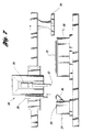
- Figure 2 depicts the main components of the apparatus used to practice the process disclosed and claimed herein.
- a flip chip 20 is loaded onto a flip chip pickup table 24.
- a substrate 22 is positioned upon a work holder 26.
- a vacuum flip chip pickup mechanism 28 is extended to pick up the flip chip 20 by use of vacuum.
- Figure 4 shows the vacuum flip chip pickup arm retracted in combination, thus elevating the flip chip 20 above the flip chip pickup table 24.
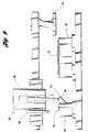
- a stage 38 which includes the vacuum flip chip pickup mechanism 28 and an ultrasonic horn 30 is translated so that the vacuum flip chip pickup arm 28 with the flip chip 20 is aligned with a squaring device 36.
- the vacuum flip chip pickup arm 28 ( Figure 6) is extended to place the flip chip 20 onto the squaring device 36.
- the vacuum flip chip pickup arm 28 is then retracted ( Figure 7) and the squaring device 36 is activated to orient the flip chip 20 so that it is square in relation to the substrate 22.
- the stage 38 is translated so that the ultrasonic horn 30 is aligned with the squaring device 36.
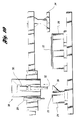
- the ultrasonic horn 30 is then extended ( Figure 9) to pick up the flip chip 20 from the squaring device 36 using a vacuum.
- the vacuum is delivered by one or more bores which extend axially through the ultrasonic horn 30 toward a supply of negative pressure.
- the disclosed horn may be used for various flip chip sizes.
- the-ultrasonic horn 30 is shown as being retracted while carrying the flip chip 20 along with it.
- the stage 38 is translated so that the ultrasonic horn 30, together with the flip chip 20, is aligned opposite a bonding location 40 defined upon the substrate 22.
- a means for alignment such as an optical device 34
- Alignment of the flip chip 20 in relation to the substrate 22 then commences by manual or automatic means.
- other alignment means may be used, such as split prisms and infrared techniques.
- Figure 13 depicts translation of the alignment device 30 to a neutral position and extension of the ultrasonic horn 30 to bring the flip chip 20 into contact with the substrate 22.
- a predetermined force of between 1 and 50 pounds and ultrasonic energy within a range of 60,000 to 100,000 oscillations per second are applied to the flip chip 20 for a predetermined time period of up to about 10 seconds.
- the ultrasonic horn 30 retracts, leaving the flip chip 20 joined to the substrate 22 by a secure diffusion bond.
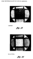
- Figures 15 and 16 are X-ray photographs of a flip chip 20 poised above a substrate 22.
- the rectangular grey area is the back side of the substrate 22.
- each dot represents a gold globule bump located on the active face of the flip chip 20. Extending away from the gold bumps is a bonding pattern which is defined by gold plated traces or leads defined on the top surface of the substrate 22.
- the gold bumps are misaligned from the bonding pattern defined on the substrate. Alignment or registration is enabled by the alignment device. Using the disclosed process and apparatus, all of the bumps disposed upon the flip chip are diffusion bonded simultaneously to the bonding sites defined upon the substrate 22.
- the ultrasonic horn when the ultrasonic horn is activated, microscopic surface contaminants and oxides are dispelled from the flip chip in the substrate, thereby producing an atomically clean surface for bonding.
- a force when a force is applied to the flip chip, it is applied in stages. First, an initial force of, for example, 5 pounds is applied, followed by a second force of up to 20-50 pounds.
- Such forces tend to plastically deform the gold bumps adjacent a region of contact between the flip chip and the substrate so that an intimate contact therebetween results and an intermetallic atomic bond is formed by isothermal ultrasonic energy.
- a 1-2 pound force should suffice. If there are 250 bumps, for example, a force amounting to 25-30 pounds should suffice if applied for a period of up to about 10-20 seconds.
- the ultrasonic probe of the disclosed apparatus may be manufactured in various forms.
- One suitable vendor is Uthe Technology of Milpitas, California.
- the disclosed probe may be used with a 50-watt generator.
- One type of flip chip attachment apparatus is manufactured by R D Automation of Piscataway, New Jersey (Model AFC-101-AP). A machine produces alignment accuracy of better than ⁇ 5 microns. Throughput amounts to 350-500 flip chips per hour depending upon the process parameters.
- M-8 flip chip bonder a thin optical probe is inserted between the flip chip and the substrate, imaging both bonding surfaces simultaneously. Two video cameras and reflection illuminators are used to view the flip chip and the substrate individually. Outputs of the video systems are superimposed on one screen ( Figures 15-16) and the alignment is achieved by moving the substrate in reference to the stationary flip chip. Final alignment is performed when the flip chip is in close proximity to its final position, after which there is no motion in the X, Y, or theta directions. The only axes upon which motion may remain is in the vertical (Z) direction.
- the substrate holder 26 may advantageously be made of granite.
- the disclosed apparatus requires no heat, no solder, and is quick. Since no heat is required, the apparatus and process can be used for heat sensitive substrate flip chip bonding media and produces less damage to the flip chip compared to thermocompression bonding or solder reflow. Throughput is enhanced because an entire flip chip can be bonded to a substrate regardless of the number of connections. Finally, since all forces are in the vertical (Z) direction, there is no relative horizontal movement between the flip chip and the substrate.
- substrates up to about 14 inches square may be accommodated within the disclosed apparatus.
- Flip chips as small as 0.05 inches square may be handled.
- Flip chips 1 inch square may also be effectively used by the disclosed process.
- the disclosed invention not only improves bonding accuracy but also facilitates throughput because the pickup tool is also the bonding tool. This eliminates the need to place, retract, and engage the flip chip with the horn.
- the disclosed apparatus is a semi-automatic system for producing high density packaging applications which require high alignment and bonding accuracy of flipped chips to the substrate.
- the ultrasonic probe of the present invention includes a tool tip which is approximately 1/4 inches square. Tools for different flip chip sizes could be changed automatically. A probe can exert forces of up to 100 kilograms.
- the substrates disclosed herein may be ceramic, epoxy laminated boards, or flexible circuits.
Landscapes
- Engineering & Computer Science (AREA)
- Mechanical Engineering (AREA)
- Wire Bonding (AREA)
- Medicines Containing Plant Substances (AREA)
Applications Claiming Priority (2)
| Application Number | Priority Date | Filing Date | Title |
|---|---|---|---|
| US239106 | 1988-08-31 | ||
| US08/239,106 US5427301A (en) | 1994-05-06 | 1994-05-06 | Ultrasonic flip chip process and apparatus |
Publications (3)
| Publication Number | Publication Date |
|---|---|
| EP0680803A2 true EP0680803A2 (fr) | 1995-11-08 |
| EP0680803A3 EP0680803A3 (fr) | 1997-01-15 |
| EP0680803B1 EP0680803B1 (fr) | 1999-08-25 |
Family
ID=22900644
Family Applications (1)
| Application Number | Title | Priority Date | Filing Date |
|---|---|---|---|
| EP95302724A Expired - Lifetime EP0680803B1 (fr) | 1994-05-06 | 1995-04-24 | Assemblage de puces sur un substrat |
Country Status (5)
| Country | Link |
|---|---|
| US (3) | US5427301A (fr) |
| EP (1) | EP0680803B1 (fr) |
| JP (1) | JPH0845994A (fr) |
| DE (1) | DE69511609T2 (fr) |
| ES (1) | ES2135009T3 (fr) |
Cited By (1)
| Publication number | Priority date | Publication date | Assignee | Title |
|---|---|---|---|---|
| CN109671651A (zh) * | 2018-12-20 | 2019-04-23 | 广东工业大学 | 一种超声释放式Micro-LED巨量转移方法 |
Families Citing this family (120)
| Publication number | Priority date | Publication date | Assignee | Title |
|---|---|---|---|---|
| JP2915350B2 (ja) * | 1996-07-05 | 1999-07-05 | 株式会社アルテクス | 超音波振動接合チップ実装装置 |
| US6071009A (en) * | 1997-10-03 | 2000-06-06 | Micron Technology, Inc. | Semiconductor wirebond machine leadframe thermal map system |
| US6045026A (en) | 1998-02-23 | 2000-04-04 | Micron Technology, Inc. | Utilize ultrasonic energy to reduce the initial contact forces in known-good-die or permanent contact systems |
| JP3176580B2 (ja) * | 1998-04-09 | 2001-06-18 | 太陽誘電株式会社 | 電子部品の実装方法及び実装装置 |
| SG75841A1 (en) | 1998-05-02 | 2000-10-24 | Eriston Invest Pte Ltd | Flip chip assembly with via interconnection |
| US6406939B1 (en) | 1998-05-02 | 2002-06-18 | Charles W. C. Lin | Flip chip assembly with via interconnection |
| US6168971B1 (en) * | 1998-05-05 | 2001-01-02 | Fujitsu Limited | Method of assembling thin film jumper connectors to a substrate |
| JP3942738B2 (ja) * | 1998-07-17 | 2007-07-11 | 松下電器産業株式会社 | バンプ接合装置及び方法、並びに半導体部品製造装置 |
| WO2000013229A1 (fr) * | 1998-09-01 | 2000-03-09 | Matsushita Electric Industrial Co., Ltd. | Dispositif pour evaluer un assemblage par bosses et procede y relatif, et dispositif de production d'un composant a semiconducteur et procede y relatif |
| JP3347295B2 (ja) * | 1998-09-09 | 2002-11-20 | 松下電器産業株式会社 | 部品実装ツールとそれによる部品実装方法および装置 |
| US6138894A (en) * | 1998-11-25 | 2000-10-31 | Intermedics Inc. | Method for coupling a circuit component to a substrate |
| EP1010492B1 (fr) * | 1998-12-10 | 2004-09-01 | Ultex Corporation | Procédé de soudage par vibration ultrasonique |
| TW396462B (en) | 1998-12-17 | 2000-07-01 | Eriston Technologies Pte Ltd | Bumpless flip chip assembly with solder via |
| TW522536B (en) | 1998-12-17 | 2003-03-01 | Wen-Chiang Lin | Bumpless flip chip assembly with strips-in-via and plating |
| TW444236B (en) | 1998-12-17 | 2001-07-01 | Charles Wen Chyang Lin | Bumpless flip chip assembly with strips and via-fill |
| JP3290632B2 (ja) * | 1999-01-06 | 2002-06-10 | 株式会社アルテクス | 超音波振動接合装置 |
| US20060261132A1 (en) * | 1999-02-25 | 2006-11-23 | Reiber Steven F | Low range bonding tool |
| US7032802B2 (en) * | 1999-02-25 | 2006-04-25 | Reiber Steven F | Bonding tool with resistance |
| US20070131661A1 (en) * | 1999-02-25 | 2007-06-14 | Reiber Steven F | Solder ball placement system |
| US20080197172A1 (en) * | 1999-02-25 | 2008-08-21 | Reiber Steven F | Bonding Tool |
| US7389905B2 (en) | 1999-02-25 | 2008-06-24 | Reiber Steven F | Flip chip bonding tool tip |
| US20060071050A1 (en) * | 1999-02-25 | 2006-04-06 | Reiber Steven F | Multi-head tab bonding tool |
| US7124927B2 (en) * | 1999-02-25 | 2006-10-24 | Reiber Steven F | Flip chip bonding tool and ball placement capillary |
| JP3428488B2 (ja) * | 1999-04-12 | 2003-07-22 | 株式会社村田製作所 | 電子部品の製造方法 |
| JP4338834B2 (ja) * | 1999-08-06 | 2009-10-07 | 日本テキサス・インスツルメンツ株式会社 | 超音波振動を用いた半導体チップの実装方法 |
| US6297562B1 (en) | 1999-09-20 | 2001-10-02 | Telefonaktieboalget Lm Ericsson (Publ) | Semiconductive chip having a bond pad located on an active device |
| JP3587748B2 (ja) * | 1999-10-18 | 2004-11-10 | ソニーケミカル株式会社 | 多層フレキシブル配線板及び多層フレキシブル配線板製造方法 |
| US6465879B1 (en) * | 1999-10-19 | 2002-10-15 | Citizen Watch Co., Ltd. | Structure for mounting semiconductor device, method of mounting same, semiconductor device, and method of fabricating same |
| US6216937B1 (en) * | 1999-12-22 | 2001-04-17 | International Business Machines Corporation | Process and apparatus to remove closely spaced chips on a multi-chip module |
| US6402970B1 (en) | 2000-08-22 | 2002-06-11 | Charles W. C. Lin | Method of making a support circuit for a semiconductor chip assembly |
| US6660626B1 (en) | 2000-08-22 | 2003-12-09 | Charles W. C. Lin | Semiconductor chip assembly with simultaneously electrolessly plated contact terminal and connection joint |
| US6562709B1 (en) | 2000-08-22 | 2003-05-13 | Charles W. C. Lin | Semiconductor chip assembly with simultaneously electroplated contact terminal and connection joint |
| US6562657B1 (en) | 2000-08-22 | 2003-05-13 | Charles W. C. Lin | Semiconductor chip assembly with simultaneously electrolessly plated contact terminal and connection joint |
| US6551861B1 (en) | 2000-08-22 | 2003-04-22 | Charles W. C. Lin | Method of making a semiconductor chip assembly by joining the chip to a support circuit with an adhesive |
| US6403460B1 (en) | 2000-08-22 | 2002-06-11 | Charles W. C. Lin | Method of making a semiconductor chip assembly |
| US6350633B1 (en) | 2000-08-22 | 2002-02-26 | Charles W. C. Lin | Semiconductor chip assembly with simultaneously electroplated contact terminal and connection joint |
| US6436734B1 (en) | 2000-08-22 | 2002-08-20 | Charles W. C. Lin | Method of making a support circuit for a semiconductor chip assembly |
| US6350632B1 (en) | 2000-09-20 | 2002-02-26 | Charles W. C. Lin | Semiconductor chip assembly with ball bond connection joint |
| US6511865B1 (en) | 2000-09-20 | 2003-01-28 | Charles W. C. Lin | Method for forming a ball bond connection joint on a conductive trace and conductive pad in a semiconductor chip assembly |
| US6350386B1 (en) | 2000-09-20 | 2002-02-26 | Charles W. C. Lin | Method of making a support circuit with a tapered through-hole for a semiconductor chip assembly |
| US6448108B1 (en) | 2000-10-02 | 2002-09-10 | Charles W. C. Lin | Method of making a semiconductor chip assembly with a conductive trace subtractively formed before and after chip attachment |
| US6544813B1 (en) | 2000-10-02 | 2003-04-08 | Charles W. C. Lin | Method of making a semiconductor chip assembly with a conductive trace subtractively formed before and after chip attachment |
| US6908788B1 (en) | 2000-10-13 | 2005-06-21 | Bridge Semiconductor Corporation | Method of connecting a conductive trace to a semiconductor chip using a metal base |
| US7129575B1 (en) | 2000-10-13 | 2006-10-31 | Bridge Semiconductor Corporation | Semiconductor chip assembly with bumped metal pillar |
| US7262082B1 (en) | 2000-10-13 | 2007-08-28 | Bridge Semiconductor Corporation | Method of making a three-dimensional stacked semiconductor package with a metal pillar and a conductive interconnect in an encapsulant aperture |
| US7190080B1 (en) | 2000-10-13 | 2007-03-13 | Bridge Semiconductor Corporation | Semiconductor chip assembly with embedded metal pillar |
| US7009297B1 (en) | 2000-10-13 | 2006-03-07 | Bridge Semiconductor Corporation | Semiconductor chip assembly with embedded metal particle |
| US7319265B1 (en) | 2000-10-13 | 2008-01-15 | Bridge Semiconductor Corporation | Semiconductor chip assembly with precision-formed metal pillar |
| US6440835B1 (en) | 2000-10-13 | 2002-08-27 | Charles W. C. Lin | Method of connecting a conductive trace to a semiconductor chip |
| US6673710B1 (en) | 2000-10-13 | 2004-01-06 | Bridge Semiconductor Corporation | Method of connecting a conductive trace and an insulative base to a semiconductor chip |
| US7094676B1 (en) | 2000-10-13 | 2006-08-22 | Bridge Semiconductor Corporation | Semiconductor chip assembly with embedded metal pillar |
| US7075186B1 (en) | 2000-10-13 | 2006-07-11 | Bridge Semiconductor Corporation | Semiconductor chip assembly with interlocked contact terminal |
| US7264991B1 (en) | 2000-10-13 | 2007-09-04 | Bridge Semiconductor Corporation | Method of connecting a conductive trace to a semiconductor chip using conductive adhesive |
| US7129113B1 (en) | 2000-10-13 | 2006-10-31 | Bridge Semiconductor Corporation | Method of making a three-dimensional stacked semiconductor package with a metal pillar in an encapsulant aperture |
| US6740576B1 (en) | 2000-10-13 | 2004-05-25 | Bridge Semiconductor Corporation | Method of making a contact terminal with a plated metal peripheral sidewall portion for a semiconductor chip assembly |
| US6876072B1 (en) | 2000-10-13 | 2005-04-05 | Bridge Semiconductor Corporation | Semiconductor chip assembly with chip in substrate cavity |
| US7414319B2 (en) | 2000-10-13 | 2008-08-19 | Bridge Semiconductor Corporation | Semiconductor chip assembly with metal containment wall and solder terminal |
| US6537851B1 (en) | 2000-10-13 | 2003-03-25 | Bridge Semiconductor Corporation | Method of connecting a bumped compliant conductive trace to a semiconductor chip |
| US6576539B1 (en) | 2000-10-13 | 2003-06-10 | Charles W.C. Lin | Semiconductor chip assembly with interlocked conductive trace |
| US6949408B1 (en) | 2000-10-13 | 2005-09-27 | Bridge Semiconductor Corporation | Method of connecting a conductive trace and an insulative base to a semiconductor chip using multiple etch steps |
| US6492252B1 (en) | 2000-10-13 | 2002-12-10 | Bridge Semiconductor Corporation | Method of connecting a bumped conductive trace to a semiconductor chip |
| US6576493B1 (en) | 2000-10-13 | 2003-06-10 | Bridge Semiconductor Corporation | Method of connecting a conductive trace and an insulative base to a semiconductor chip using multiple etch steps |
| US7071089B1 (en) | 2000-10-13 | 2006-07-04 | Bridge Semiconductor Corporation | Method of making a semiconductor chip assembly with a carved bumped terminal |
| US7132741B1 (en) | 2000-10-13 | 2006-11-07 | Bridge Semiconductor Corporation | Semiconductor chip assembly with carved bumped terminal |
| US6872591B1 (en) | 2000-10-13 | 2005-03-29 | Bridge Semiconductor Corporation | Method of making a semiconductor chip assembly with a conductive trace and a substrate |
| US6984576B1 (en) | 2000-10-13 | 2006-01-10 | Bridge Semiconductor Corporation | Method of connecting an additively and subtractively formed conductive trace and an insulative base to a semiconductor chip |
| US6667229B1 (en) | 2000-10-13 | 2003-12-23 | Bridge Semiconductor Corporation | Method of connecting a bumped compliant conductive trace and an insulative base to a semiconductor chip |
| US6548393B1 (en) | 2000-10-13 | 2003-04-15 | Charles W. C. Lin | Semiconductor chip assembly with hardened connection joint |
| US6699780B1 (en) | 2000-10-13 | 2004-03-02 | Bridge Semiconductor Corporation | Method of connecting a conductive trace to a semiconductor chip using plasma undercut etching |
| US6444489B1 (en) | 2000-12-15 | 2002-09-03 | Charles W. C. Lin | Semiconductor chip assembly with bumped molded substrate |
| JP3626688B2 (ja) | 2001-01-11 | 2005-03-09 | アルプス電気株式会社 | 微動トラッキング装置を有する磁気ヘッドアクチュエータ |
| US6653170B1 (en) | 2001-02-06 | 2003-11-25 | Charles W. C. Lin | Semiconductor chip assembly with elongated wire ball bonded to chip and electrolessly plated to support circuit |
| EP1415328A2 (fr) * | 2001-08-01 | 2004-05-06 | Lilogix, Inc. doing business as RD Automation | Procede et appareil de montage de composants semiconducteurs sur des substrats et elements associes |
| US6951655B2 (en) * | 2001-10-11 | 2005-10-04 | Imi Biomed, Inc. | Pro-micelle pharmaceutical compositions |
| US6838316B2 (en) * | 2002-03-06 | 2005-01-04 | Kabushiki Kaisha Toshiba | Semiconductor device manufacturing method using ultrasonic flip chip bonding technique |
| WO2004061953A2 (fr) * | 2002-12-31 | 2004-07-22 | Massachusetts Institute Of Technology | Procede de realisation d'une structure de semi-conducteurs multicouches integrant un tenon de traitement |
| US7064055B2 (en) * | 2002-12-31 | 2006-06-20 | Massachusetts Institute Of Technology | Method of forming a multi-layer semiconductor structure having a seamless bonding interface |
| US7040012B2 (en) * | 2003-03-07 | 2006-05-09 | Intel Corporation | Method of electrically and mechanically connecting electronic devices to one another |
| JP3921459B2 (ja) * | 2003-07-11 | 2007-05-30 | ソニーケミカル&インフォメーションデバイス株式会社 | 電気部品の実装方法及び実装装置 |
| US20050095744A1 (en) * | 2003-10-20 | 2005-05-05 | Song-Hua Shi | System to couple integrated circuit die to substrate |
| US7993983B1 (en) | 2003-11-17 | 2011-08-09 | Bridge Semiconductor Corporation | Method of making a semiconductor chip assembly with chip and encapsulant grinding |
| US7425759B1 (en) | 2003-11-20 | 2008-09-16 | Bridge Semiconductor Corporation | Semiconductor chip assembly with bumped terminal and filler |
| US7538415B1 (en) | 2003-11-20 | 2009-05-26 | Bridge Semiconductor Corporation | Semiconductor chip assembly with bumped terminal, filler and insulative base |
| US20050109746A1 (en) * | 2003-11-26 | 2005-05-26 | International Business Machines Corporation | Method for fluxless soldering of workpieces |
| US20060003548A1 (en) * | 2004-06-30 | 2006-01-05 | Kobrinsky Mauro J | Highly compliant plate for wafer bonding |
| US7458495B2 (en) | 2004-10-13 | 2008-12-02 | Asm Assembly Automation Ltd. | Flip chip bonding tool |
| US7446419B1 (en) | 2004-11-10 | 2008-11-04 | Bridge Semiconductor Corporation | Semiconductor chip assembly with welded metal pillar of stacked metal balls |
| US7750483B1 (en) | 2004-11-10 | 2010-07-06 | Bridge Semiconductor Corporation | Semiconductor chip assembly with welded metal pillar and enlarged plated contact terminal |
| US7268421B1 (en) | 2004-11-10 | 2007-09-11 | Bridge Semiconductor Corporation | Semiconductor chip assembly with welded metal pillar that includes enlarged ball bond |
| CH697279B1 (de) * | 2004-12-06 | 2008-07-31 | Oerlikon Assembly Equipment Ag | Verfahren für die Montage eines Halbleiterchips auf einem Substrat. |
| CN2810964Y (zh) * | 2005-05-31 | 2006-08-30 | 刘映辉 | 自动超声波焊贴机 |
| US20070085085A1 (en) * | 2005-08-08 | 2007-04-19 | Reiber Steven F | Dissipative pick and place tools for light wire and LED displays |
| JP4728782B2 (ja) * | 2005-11-15 | 2011-07-20 | パナソニック株式会社 | 半導体装置およびその製造方法 |
| DE102006020418A1 (de) * | 2006-04-26 | 2007-10-31 | Herrmann Ultraschalltechnik Gmbh & Co. Kg | Vorrichtung zum Bearbeiten von Werkstücken mittels Ultraschall |
| US7494843B1 (en) | 2006-12-26 | 2009-02-24 | Bridge Semiconductor Corporation | Method of making a semiconductor chip assembly with thermal conductor and encapsulant grinding |
| US7811863B1 (en) | 2006-10-26 | 2010-10-12 | Bridge Semiconductor Corporation | Method of making a semiconductor chip assembly with metal pillar and encapsulant grinding and heat sink attachment |
| JP2008218528A (ja) * | 2007-02-28 | 2008-09-18 | Fujitsu Ltd | 電子部品の実装方法および製造装置 |
| JP2007288220A (ja) * | 2007-08-03 | 2007-11-01 | Matsushita Electric Ind Co Ltd | 電子部品のボンディングツールおよび電子部品のボンディング装置 |
| DE102007045418B4 (de) * | 2007-09-21 | 2011-05-12 | Sew-Eurodrive Gmbh & Co. Kg | Herstellungsverfahren für eine Anordnung zum Kühlen eines elektrischen Bauelements |
| US8505805B2 (en) * | 2008-10-09 | 2013-08-13 | Honeywell International Inc. | Systems and methods for platinum ball bonding |
| US8611636B1 (en) | 2009-01-05 | 2013-12-17 | Cognex Corporation | High speed method of aligning components having a plurality of non-uniformly spaced features |
| US8129220B2 (en) * | 2009-08-24 | 2012-03-06 | Hong Kong Polytechnic University | Method and system for bonding electrical devices using an electrically conductive adhesive |
| US7845543B1 (en) * | 2009-11-17 | 2010-12-07 | Asm Assembly Automation Ltd | Apparatus and method for bonding multiple dice |
| US8113411B2 (en) * | 2010-03-30 | 2012-02-14 | Flextronics Ap, Llc | Universal radio frequency shield removal |
| US8755925B2 (en) | 2011-11-18 | 2014-06-17 | Nike, Inc. | Automated identification and assembly of shoe parts |
| US10552551B2 (en) | 2011-11-18 | 2020-02-04 | Nike, Inc. | Generation of tool paths for shore assembly |
| US8958901B2 (en) | 2011-11-18 | 2015-02-17 | Nike, Inc. | Automated manufacturing of shoe parts |
| US8849620B2 (en) | 2011-11-18 | 2014-09-30 | Nike, Inc. | Automated 3-D modeling of shoe parts |
| US8960745B2 (en) | 2011-11-18 | 2015-02-24 | Nike, Inc | Zoned activation manufacturing vacuum tool |
| US9451810B2 (en) | 2011-11-18 | 2016-09-27 | Nike, Inc. | Automated identification of shoe parts |
| US8858744B2 (en) * | 2011-11-18 | 2014-10-14 | Nike, Inc. | Multi-functional manufacturing tool |
| US8696043B2 (en) * | 2011-11-18 | 2014-04-15 | Nike, Inc. | Hybrid pickup tool |
| US9010827B2 (en) | 2011-11-18 | 2015-04-21 | Nike, Inc. | Switchable plate manufacturing vacuum tool |
| JP5768677B2 (ja) * | 2011-11-22 | 2015-08-26 | 株式会社デンソー | バンプ接合構造体の製造方法 |
| JP6218669B2 (ja) * | 2014-05-13 | 2017-10-25 | 東洋自動機株式会社 | エアバッグ付き袋への気体封入方法及び気体封入装置 |
| DE102015106265A1 (de) * | 2015-02-06 | 2016-08-11 | Auto-Kabel Management Gmbh | Ultraschallschweißvorrichtung sowie Verfahren zum Ultraschallschweißen |
| JP7181217B2 (ja) * | 2017-04-04 | 2022-11-30 | クリック アンド ソッファ インダストリーズ、インク. | 超音波溶接システムおよびその使用方法 |
| KR20230019842A (ko) * | 2020-06-03 | 2023-02-09 | 쿨리케 앤드 소파 인더스트리즈, 인코포레이티드 | 초음파 용접 시스템, 이를 사용하는 방법, 및 용접된 전도성 핀을 포함하는 관련 작업물 |
| WO2022222148A1 (fr) * | 2021-04-23 | 2022-10-27 | 重庆康佳光电技术研究院有限公司 | Procédé et appareil de transfert de puce, fond de panier d'affichage et dispositif d'affichage |
| JP7697893B2 (ja) * | 2022-02-03 | 2025-06-24 | トヨタ自動車株式会社 | 超音波接合方法及び超音波接合装置 |
Family Cites Families (21)
| Publication number | Priority date | Publication date | Assignee | Title |
|---|---|---|---|---|
| US3403438A (en) * | 1964-12-02 | 1968-10-01 | Corning Glass Works | Process for joining transistor chip to printed circuit |
| US3470611A (en) * | 1967-04-11 | 1969-10-07 | Corning Glass Works | Semiconductor device assembly method |
| US3563443A (en) * | 1969-03-19 | 1971-02-16 | Hugle Ind Inc | Pneumatic force-exerting system |
| US3750926A (en) * | 1971-03-02 | 1973-08-07 | Hitachi Ltd | Vibration element for supersonic bonding |
| US3938722A (en) * | 1973-04-30 | 1976-02-17 | Mech-El Industries, Inc. | Ultrasonic thermal compression beam lead, flip chip bonder |
| US3964664A (en) * | 1974-03-13 | 1976-06-22 | P. R. Mallory & Co., Inc. | Beam leaded device welding machine |
| US3986255A (en) * | 1974-11-29 | 1976-10-19 | Itek Corporation | Process for electrically interconnecting chips with substrates employing gold alloy bumps and magnetic materials therein |
| US4411721A (en) * | 1982-02-25 | 1983-10-25 | The Mead Corporation | Apparatus and method for attaching fastener tapes |
| JPS63119552A (ja) * | 1986-11-07 | 1988-05-24 | Sharp Corp | Lsiチツプ |
| US5591298A (en) * | 1988-01-19 | 1997-01-07 | Kimberly-Clark Corporation | Machine for ultrasonic bonding |
| US4842662A (en) * | 1988-06-01 | 1989-06-27 | Hewlett-Packard Company | Process for bonding integrated circuit components |
| US4848639A (en) * | 1988-09-29 | 1989-07-18 | Ag Communication Systems Corporation | Compliant pad for use in tape automated bonding process |
| US4899921A (en) * | 1988-10-28 | 1990-02-13 | The American Optical Corporation | Aligner bonder |
| US5250843A (en) * | 1991-03-27 | 1993-10-05 | Integrated System Assemblies Corp. | Multichip integrated circuit modules |
| US5234369A (en) * | 1991-07-31 | 1993-08-10 | Hunter's Specialties, Inc. | Animal call, and methods of and apparatus for making same |
| US5178605A (en) * | 1991-09-23 | 1993-01-12 | Alcon Surgical, Inc. | Coaxial flow irrigating and aspirating ultrasonic handpiece |
| US5288007A (en) * | 1991-10-04 | 1994-02-22 | International Business Machine Corporation | Apparatus and methods for making simultaneous electrical connections |
| US5347086A (en) * | 1992-03-24 | 1994-09-13 | Microelectronics And Computer Technology Corporation | Coaxial die and substrate bumps |
| US5170929A (en) * | 1992-05-29 | 1992-12-15 | International Business Machines Corporation | Ultrasonic adhesion/dehesion monitoring apparatus with acoustic transducer means |
| US5398863A (en) * | 1993-07-23 | 1995-03-21 | Tessera, Inc. | Shaped lead structure and method |
| US5341979A (en) * | 1993-09-03 | 1994-08-30 | Motorola, Inc. | Method of bonding a semiconductor substrate to a support substrate and structure therefore |
-
1994
- 1994-05-06 US US08/239,106 patent/US5427301A/en not_active Expired - Fee Related
-
1995
- 1995-04-24 DE DE69511609T patent/DE69511609T2/de not_active Expired - Fee Related
- 1995-04-24 EP EP95302724A patent/EP0680803B1/fr not_active Expired - Lifetime
- 1995-04-24 ES ES95302724T patent/ES2135009T3/es not_active Expired - Lifetime
- 1995-05-01 JP JP7107624A patent/JPH0845994A/ja active Pending
- 1995-06-23 US US08/494,217 patent/US5655700A/en not_active Expired - Fee Related
-
1996
- 1996-11-04 US US08/743,580 patent/US5669545A/en not_active Expired - Fee Related
Cited By (1)
| Publication number | Priority date | Publication date | Assignee | Title |
|---|---|---|---|---|
| CN109671651A (zh) * | 2018-12-20 | 2019-04-23 | 广东工业大学 | 一种超声释放式Micro-LED巨量转移方法 |
Also Published As
| Publication number | Publication date |
|---|---|
| DE69511609D1 (de) | 1999-09-30 |
| US5427301A (en) | 1995-06-27 |
| EP0680803A3 (fr) | 1997-01-15 |
| JPH0845994A (ja) | 1996-02-16 |
| ES2135009T3 (es) | 1999-10-16 |
| US5669545A (en) | 1997-09-23 |
| US5655700A (en) | 1997-08-12 |
| DE69511609T2 (de) | 1999-12-09 |
| EP0680803B1 (fr) | 1999-08-25 |
Similar Documents
| Publication | Publication Date | Title |
|---|---|---|
| EP0680803B1 (fr) | Assemblage de puces sur un substrat | |
| EP0320244B1 (fr) | Points de contacts électriques et boitier en étant pourvu | |
| US5297333A (en) | Packaging method for flip-chip type semiconductor device | |
| EP1386356B1 (fr) | Interconnexion par billes sans flux | |
| US9120169B2 (en) | Method for device packaging | |
| US5316204A (en) | Method for bonding lead with electrode of electronic device | |
| KR970012964A (ko) | 결합 재료 범프에 의해 상호접속되는 시스템 | |
| TWI804584B (zh) | 用於重工倒裝晶片組件的裝置及方法 | |
| JPH0779152B2 (ja) | フリップチップ型半導体装置の実装方法 | |
| JP4780858B2 (ja) | 半導体装置の製造方法 | |
| JPH07106334A (ja) | 光学半導体装置を光学基板に付着する方法 | |
| JPH08162502A (ja) | 電子部品実装装置 | |
| JP2003174061A (ja) | ボンディング装置及びボンディング方法 | |
| CN1259705C (zh) | 祼芯片安装方法及安装系统 | |
| JP4083533B2 (ja) | 半導体装置の製造方法 | |
| JPH10223687A (ja) | フリップチップ実装モジュール及び製造方法、製造装置 | |
| JPH08139096A (ja) | 電子部品及び電子部品の実装方法並びに電子部品の実装装置 | |
| JPH09181491A (ja) | 半導体装置の実装方法及び実装構造 | |
| JPS6224635A (ja) | フリツプチツプボンダ− | |
| JP2003258012A (ja) | バンプ付け装置 | |
| Oppert et al. | Micro ball bumping packaging for wafer level & 3-d solder sphere transfer and solder jetting | |
| JPH06310569A (ja) | 半導体素子のフェースダウンボンディング法 | |
| JP2633631B2 (ja) | 電子部品の実装装置 | |
| JP3086124B2 (ja) | ボンディング用バンプの形成方法および装置 | |
| JP2004363399A (ja) | 電子部品のダイボンディング方法及びダイボンディング装置 |
Legal Events
| Date | Code | Title | Description |
|---|---|---|---|
| PUAI | Public reference made under article 153(3) epc to a published international application that has entered the european phase |
Free format text: ORIGINAL CODE: 0009012 |
|
| AK | Designated contracting states |
Kind code of ref document: A2 Designated state(s): DE ES FR GB |
|
| PUAL | Search report despatched |
Free format text: ORIGINAL CODE: 0009013 |
|
| AK | Designated contracting states |
Kind code of ref document: A3 Designated state(s): DE ES FR GB |
|
| 17P | Request for examination filed |
Effective date: 19970613 |
|
| 17Q | First examination report despatched |
Effective date: 19971119 |
|
| GRAG | Despatch of communication of intention to grant |
Free format text: ORIGINAL CODE: EPIDOS AGRA |
|
| GRAG | Despatch of communication of intention to grant |
Free format text: ORIGINAL CODE: EPIDOS AGRA |
|
| GRAH | Despatch of communication of intention to grant a patent |
Free format text: ORIGINAL CODE: EPIDOS IGRA |
|
| GRAH | Despatch of communication of intention to grant a patent |
Free format text: ORIGINAL CODE: EPIDOS IGRA |
|
| GRAA | (expected) grant |
Free format text: ORIGINAL CODE: 0009210 |
|
| AK | Designated contracting states |
Kind code of ref document: B1 Designated state(s): DE ES FR GB |
|
| REF | Corresponds to: |
Ref document number: 69511609 Country of ref document: DE Date of ref document: 19990930 |
|
| REG | Reference to a national code |
Ref country code: ES Ref legal event code: FG2A Ref document number: 2135009 Country of ref document: ES Kind code of ref document: T3 |
|
| ET | Fr: translation filed | ||
| PLBE | No opposition filed within time limit |
Free format text: ORIGINAL CODE: 0009261 |
|
| STAA | Information on the status of an ep patent application or granted ep patent |
Free format text: STATUS: NO OPPOSITION FILED WITHIN TIME LIMIT |
|
| 26N | No opposition filed | ||
| PGFP | Annual fee paid to national office [announced via postgrant information from national office to epo] |
Ref country code: ES Payment date: 20010417 Year of fee payment: 7 |
|
| REG | Reference to a national code |
Ref country code: GB Ref legal event code: IF02 |
|
| PG25 | Lapsed in a contracting state [announced via postgrant information from national office to epo] |
Ref country code: ES Free format text: LAPSE BECAUSE OF NON-PAYMENT OF DUE FEES Effective date: 20020425 |
|
| PGFP | Annual fee paid to national office [announced via postgrant information from national office to epo] |
Ref country code: GB Payment date: 20030326 Year of fee payment: 9 |
|
| PGFP | Annual fee paid to national office [announced via postgrant information from national office to epo] |
Ref country code: DE Payment date: 20030331 Year of fee payment: 9 |
|
| PGFP | Annual fee paid to national office [announced via postgrant information from national office to epo] |
Ref country code: FR Payment date: 20030408 Year of fee payment: 9 |
|
| PG25 | Lapsed in a contracting state [announced via postgrant information from national office to epo] |
Ref country code: GB Free format text: LAPSE BECAUSE OF NON-PAYMENT OF DUE FEES Effective date: 20040424 |
|
| REG | Reference to a national code |
Ref country code: ES Ref legal event code: FD2A Effective date: 20030514 |
|
| PG25 | Lapsed in a contracting state [announced via postgrant information from national office to epo] |
Ref country code: DE Free format text: LAPSE BECAUSE OF NON-PAYMENT OF DUE FEES Effective date: 20041103 |
|
| GBPC | Gb: european patent ceased through non-payment of renewal fee |
Effective date: 20040424 |
|
| PG25 | Lapsed in a contracting state [announced via postgrant information from national office to epo] |
Ref country code: FR Free format text: LAPSE BECAUSE OF NON-PAYMENT OF DUE FEES Effective date: 20041231 |
|
| REG | Reference to a national code |
Ref country code: FR Ref legal event code: ST |