EP0681884B1 - Unterwasserdrahtschneidefunkenerosionsmaschine - Google Patents
Unterwasserdrahtschneidefunkenerosionsmaschine Download PDFInfo
- Publication number
- EP0681884B1 EP0681884B1 EP19950302998 EP95302998A EP0681884B1 EP 0681884 B1 EP0681884 B1 EP 0681884B1 EP 19950302998 EP19950302998 EP 19950302998 EP 95302998 A EP95302998 A EP 95302998A EP 0681884 B1 EP0681884 B1 EP 0681884B1
- Authority
- EP
- European Patent Office
- Prior art keywords
- machining
- vessel
- electrical discharge
- wire cutting
- equipment
- Prior art date
- Legal status (The legal status is an assumption and is not a legal conclusion. Google has not performed a legal analysis and makes no representation as to the accuracy of the status listed.)
- Expired - Lifetime
Links
Images
Classifications
-
- B—PERFORMING OPERATIONS; TRANSPORTING
- B23—MACHINE TOOLS; METAL-WORKING NOT OTHERWISE PROVIDED FOR
- B23H—WORKING OF METAL BY THE ACTION OF A HIGH CONCENTRATION OF ELECTRIC CURRENT ON A WORKPIECE USING AN ELECTRODE WHICH TAKES THE PLACE OF A TOOL; SUCH WORKING COMBINED WITH OTHER FORMS OF WORKING OF METAL
- B23H7/00—Processes or apparatus applicable to both electrical discharge machining and electrochemical machining
- B23H7/02—Wire-cutting
Definitions
- This invention relates to an improvement applicable to submerged type wire cutting electrical discharge machining equipment. More specifically, this invention relates to an improvement developed for preventing machining chips produced during electrical discharge machining from sticking to the movable members of the equipment which are immersed in a machining liquid and for making the maintenance of the equipment easy.
- Wire cutting electrical discharge machining equipment is defined as equipment employable for machining a metal work by electrical discharge which takes place between the metal work and a wire electrode which extends between upper and lower wire guides. During a period in which electrical discharge machining is conducted, a machining liquid is sprayed to a machining region or an electrical discharge gap which is a gap between the work and the wire electrode remained for allowing electric discharge to occur therein, from the upper and lower wire guides.
- the wire cutting electrical discharge machining equipment is classified into two, a non-submerged type and a submerged type.
- the machining region In the case of a non-submerged type wire cutting electrical discharge machining equipment, the machining region is not immersed in the machining liquid but is arranged in a machining vessel to prevent the machining liquid from splashing around the equipment.
- the machining region In the case of a submerged type wire cutting electrical discharge machining equipment, the machining region is immersed in the machining liquid which is filled in a machining vessel.
- the wire electrode is a fine metal wire having an approximate diameter of 0.3 mm
- the machining chip produced during electrical discharge machining is fine metal powder having an approximate diameter of several 10 micrometers
- the machining chips of nonsubmerged type wire cutting electrical discharge machining readily flow away from the machining region with the machining liquid and there is little possibility for the machining chips to stick to the members located in the neighbourhood of the machining region.
- the machining chips are inclined to stick to the inner surface of the machining vessel, the movable members of the equipment located in the neighbourhood of the machining region, etc., including a sliding surface of the lower wire guide supporting arm which penetrates the machining vessel and the door of the machining vessel. Therefore, the submerged type wire cutting electrical discharge machining equipment available in the prior art is involved with a drawback in which the machining chips stuck onto the movable members thereof prevent the movable members of the equipment from smoothly operating.
- the object of this invention is to provide submerged type wire cutting electrical discharge machining equipment which is free from a drawback in which the machining chips stick to the movable members of the equipment such as slidable parts of the lower wire guide supporting arm, resulting in advantages that the movable members of the equipment are allowed to smoothly operate and that the maintenance of the submerged type wire cutting electrical discharge machining equipment is easy.
- submerged type wire cutting electrical discharge machining equipment provides a machining vessel consisting of a lower vessel and an upper vessel separated from each other by a membrane which is penetrated by a lower wire guide, which allows a limited quantity of liquid to flow therepast from the lower vessel to the upper vessel and which is slidable along the lower surface of a work supporting bed, the machining vessel being further provided with a liquid pressure control means for maintaining the liquid pressure in the lower vessel higher than the liquid pressure in the upper vessel.
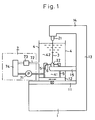
- base 1 supports an X-table 11 and a Y-table 12 which are movable thereon in the directions respectively of the X direction and of the Y direction.
- An upper wire guide supporting arm 14 horizontally extending from a column 13 vertically extending from the bed 1, supports an upper wire guide 21.
- a wire electrode 3 is extended with tension between the upper wire guide 21 and a lower wire guide 22 supported by a lower wire guide supporting arm 15 which horizontally extends from the column 13.
- a machining vessel 4 penetrated by the lower wire guide supporting arm 15 is arranged on the X-table 11 and the Y table 12 which are movable respectively in the X direction and the Y direction.
- a work supporting bed 5 is placed in the machining vessel 4 to hold a work (not shown) thereon.
- a membrane 6 which is penetrated by the lower wire guide 22 but allows a marginal quantity of the machining liquid to flow through clearances between the membrane and the work supporting bed 5, is arranged to be allowed to slide against the lower surface of the work supporting bed 5 upon movement of the bed with the tables 11, 12. In this manner, the machining vessel 4 is divided into a lower vessel 41 and an upper vessel 42 by the membrane 6.
- a liquid pressure control means 7 consisting of a pump 71, a machining liquid drain tube, a strainer 73 and a machining liquid tank 74, functions to maintain the liquid pressure of the lower vessel 41 higher than the liquid pressure of the upper vessel 42 and to drain the liquid from the upper vessel 42. This is because the membrane 6 is urged toward the lower surface of the work supporting bed 5 whilst allowing the machining liquid to flow to a limited extent past the membrane 6, into the upper vessel 42 from the lower vessel 41. When the machining liquid is drained from the upper vessel 42, the machining chips flow away from the upper vessel 42.
- a non-circulation system can be employed, and the strainer 73 and the machining liquid tank 74 can be eliminated.
- the machining chips there remains little possibility for the machining chips to stick to the movable members of the submerged type wire cutting electrical discharge machining equipment, such as the lower wire guide supporting arm 15 which penetrates the machining vessel 4 into the lower vessel 41 and much possibility for the movable members to smoothly operate.
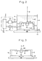
- a machining vessel 4 is arranged on an X-table 11 and a Y-table 12.
- a lower wire guide supporting arm 15 which is supported by a column (not shown) and which supports a lower guide 22 which guides a wire electrode 3, extends in the direction perpendicular to the page.
- a work supporting bed 5 is placed in the machining vessel 4 to support a work (not shown).
- a membrane 6 of a soft film e.g. a rubber film is arranged to be urged against and to be slidable along the lower and inner side surfaces of the work supporting bed 5, thus separating the machining vessel 4 into a lower vessel 41 and an upper vessel 42, when the membrane 6 is urged toward the lower surface of the work supporting bed 5 by the liquid pressure in the lower vessel 41.
- a liquid pressure control means 7 consisting of a pump 71, a liquid drain tube 72, a strainer 73 and a machining liquid tank 74, supplies a machining liquid into the lower vessel 41 and draws the machining liquid from the upper vessel 42 in which machining is conducted.
- a membrane consisting of a hard plate e.g. a metal plate and which is supported by a lower wire guide supporting arm 15, is arranged to be slidable against the lower surface of the work supporting bed 5.
Landscapes
- Chemical & Material Sciences (AREA)
- Chemical Kinetics & Catalysis (AREA)
- Electrochemistry (AREA)
- Engineering & Computer Science (AREA)
- Mechanical Engineering (AREA)
- Electrical Discharge Machining, Electrochemical Machining, And Combined Machining (AREA)
Claims (1)
- Drahtschneidefunkenerosionsmaschine des untergetauchten Typs mit einem Formgebungsbehälter (4), der aus einem unteren Behälter (41) und einem oberen Behälter (42) besteht, die voneinander durch eine Membran (6) getrennt sind, die von einer unteren Drahtführung (22) durchdrungen wird, die es gestattet, daß eine begrenzte Menge der Flüssigkeit hinter diese vom unteren Behälter zum oberen Behälter fließt, und die sich entlang der unteren Oberfläche eines Werkstückstützbettes (5) verschiebt, wobei der Formgebungsbehälter weiter mit einer Flüssigkeitsdrucksteuervorrichtung (7) für das Aufrechthalten eines Flüssigkeitsdruckes im unteren Behälter, der höher ist als der Flüssigkeitsdruck im oberen Behälter, versehen ist.
Applications Claiming Priority (2)
| Application Number | Priority Date | Filing Date | Title |
|---|---|---|---|
| JP97659/94 | 1994-05-11 | ||
| JP9765994A JPH07299661A (ja) | 1994-05-11 | 1994-05-11 | 浸漬型ワイヤカット放電加工機 |
Publications (2)
| Publication Number | Publication Date |
|---|---|
| EP0681884A1 EP0681884A1 (de) | 1995-11-15 |
| EP0681884B1 true EP0681884B1 (de) | 1998-01-28 |
Family
ID=14198197
Family Applications (1)
| Application Number | Title | Priority Date | Filing Date |
|---|---|---|---|
| EP19950302998 Expired - Lifetime EP0681884B1 (de) | 1994-05-11 | 1995-05-02 | Unterwasserdrahtschneidefunkenerosionsmaschine |
Country Status (3)
| Country | Link |
|---|---|
| EP (1) | EP0681884B1 (de) |
| JP (1) | JPH07299661A (de) |
| DE (1) | DE69501518T2 (de) |
Family Cites Families (1)
| Publication number | Priority date | Publication date | Assignee | Title |
|---|---|---|---|---|
| DE3738251C2 (de) * | 1986-11-17 | 1994-09-22 | Inst Tech Precision Eng | Funkenerosive Drahtschneidemaschine |
-
1994
- 1994-05-11 JP JP9765994A patent/JPH07299661A/ja active Pending
-
1995
- 1995-05-02 DE DE1995601518 patent/DE69501518T2/de not_active Expired - Fee Related
- 1995-05-02 EP EP19950302998 patent/EP0681884B1/de not_active Expired - Lifetime
Also Published As
| Publication number | Publication date |
|---|---|
| EP0681884A1 (de) | 1995-11-15 |
| DE69501518T2 (de) | 1998-06-04 |
| DE69501518D1 (de) | 1998-03-05 |
| JPH07299661A (ja) | 1995-11-14 |
Similar Documents
| Publication | Publication Date | Title |
|---|---|---|
| US4808787A (en) | Wire-cut electrical discharge machining equipment | |
| JPS603934B2 (ja) | 放電加工方法及び装置 | |
| EP0681884B1 (de) | Unterwasserdrahtschneidefunkenerosionsmaschine | |
| US4033832A (en) | Method for selective plating | |
| EP0507741A2 (de) | Drahtschneide-Elektroentladungsmaschine | |
| KR960013239B1 (ko) | 태핑작업할때 탭으로의 절삭유 공급장치 | |
| KR870001093B1 (ko) | 도금장치 | |
| EP0707917A1 (de) | Unterwasserdrahtschneidefunkenerosionsmaschine | |
| JP2691487B2 (ja) | ワイヤカット放電加工装置 | |
| KR940000673B1 (ko) | 방전가공기의 칩 제거장치 | |
| US3536599A (en) | Electrolytic cavity sinking apparatus and method with pressure means for forcing a machined slug from the electrode | |
| JPH01257522A (ja) | ワイヤ放電加工装置 | |
| JPS59152027A (ja) | 放電加工装置 | |
| JPS5843121B2 (ja) | 泡鐘式気液接触装置の製造方法 | |
| CN218835841U (zh) | 一种限位导向相结合的浮升结构 | |
| CN220137936U (zh) | 具有防水功能的点歌机 | |
| JPH06134622A (ja) | ワイヤ放電加工機 | |
| JPH01205920A (ja) | ワイヤカット放電加工機 | |
| JPH0938830A (ja) | 放電加工装置 | |
| JPS5894934A (ja) | ワイヤカツト放電加工装置 | |
| JPH0751983A (ja) | 切削油の供給装置 | |
| JPS588774Y2 (ja) | 半導体ウエハ−のバンプメッキ装置 | |
| CN119260411A (zh) | 具有切断功能的金属材料折弯装置 | |
| JPH0257699A (ja) | 部分めっき装置 | |
| JP3282137B2 (ja) | 電解加工装置 |
Legal Events
| Date | Code | Title | Description |
|---|---|---|---|
| PUAI | Public reference made under article 153(3) epc to a published international application that has entered the european phase |
Free format text: ORIGINAL CODE: 0009012 |
|
| AK | Designated contracting states |
Kind code of ref document: A1 Designated state(s): CH DE LI |
|
| 17P | Request for examination filed |
Effective date: 19960426 |
|
| GRAG | Despatch of communication of intention to grant |
Free format text: ORIGINAL CODE: EPIDOS AGRA |
|
| 17Q | First examination report despatched |
Effective date: 19970418 |
|
| GRAG | Despatch of communication of intention to grant |
Free format text: ORIGINAL CODE: EPIDOS AGRA |
|
| GRAH | Despatch of communication of intention to grant a patent |
Free format text: ORIGINAL CODE: EPIDOS IGRA |
|
| GRAH | Despatch of communication of intention to grant a patent |
Free format text: ORIGINAL CODE: EPIDOS IGRA |
|
| GRAA | (expected) grant |
Free format text: ORIGINAL CODE: 0009210 |
|
| AK | Designated contracting states |
Kind code of ref document: B1 Designated state(s): CH DE LI |
|
| REG | Reference to a national code |
Ref country code: CH Ref legal event code: NV Representative=s name: R. A. EGLI & CO. PATENTANWAELTE Ref country code: CH Ref legal event code: EP |
|
| REF | Corresponds to: |
Ref document number: 69501518 Country of ref document: DE Date of ref document: 19980305 |
|
| PLBE | No opposition filed within time limit |
Free format text: ORIGINAL CODE: 0009261 |
|
| STAA | Information on the status of an ep patent application or granted ep patent |
Free format text: STATUS: NO OPPOSITION FILED WITHIN TIME LIMIT |
|
| 26N | No opposition filed | ||
| PGFP | Annual fee paid to national office [announced via postgrant information from national office to epo] |
Ref country code: DE Payment date: 20010423 Year of fee payment: 7 |
|
| PG25 | Lapsed in a contracting state [announced via postgrant information from national office to epo] |
Ref country code: DE Free format text: LAPSE BECAUSE OF NON-PAYMENT OF DUE FEES Effective date: 20021203 |
|
| PGFP | Annual fee paid to national office [announced via postgrant information from national office to epo] |
Ref country code: CH Payment date: 20090513 Year of fee payment: 15 |
|
| REG | Reference to a national code |
Ref country code: CH Ref legal event code: PL |
|
| PG25 | Lapsed in a contracting state [announced via postgrant information from national office to epo] |
Ref country code: LI Free format text: LAPSE BECAUSE OF NON-PAYMENT OF DUE FEES Effective date: 20100531 Ref country code: CH Free format text: LAPSE BECAUSE OF NON-PAYMENT OF DUE FEES Effective date: 20100531 |