EP0686527B1 - Sack für ein Luftsacksystem und sein Herstellungsverfahren - Google Patents
Sack für ein Luftsacksystem und sein Herstellungsverfahren Download PDFInfo
- Publication number
- EP0686527B1 EP0686527B1 EP95108839A EP95108839A EP0686527B1 EP 0686527 B1 EP0686527 B1 EP 0686527B1 EP 95108839 A EP95108839 A EP 95108839A EP 95108839 A EP95108839 A EP 95108839A EP 0686527 B1 EP0686527 B1 EP 0686527B1
- Authority
- EP
- European Patent Office
- Prior art keywords
- bag
- base cloth
- cloths
- forming
- auxiliary
- Prior art date
- Legal status (The legal status is an assumption and is not a legal conclusion. Google has not performed a legal analysis and makes no representation as to the accuracy of the status listed.)
- Expired - Lifetime
Links
- 238000004519 manufacturing process Methods 0.000 title claims description 22
- 239000004744 fabric Substances 0.000 claims description 53
- 238000000034 method Methods 0.000 claims description 14
- 238000003466 welding Methods 0.000 claims description 4
- 238000007796 conventional method Methods 0.000 description 3
- 238000010586 diagram Methods 0.000 description 2
- 230000000452 restraining effect Effects 0.000 description 2
- 239000004677 Nylon Substances 0.000 description 1
- 230000001419 dependent effect Effects 0.000 description 1
- 238000005516 engineering process Methods 0.000 description 1
- 230000002349 favourable effect Effects 0.000 description 1
- 238000005304 joining Methods 0.000 description 1
- 229920001778 nylon Polymers 0.000 description 1
- 229920000728 polyester Polymers 0.000 description 1
Images



Classifications
-
- B—PERFORMING OPERATIONS; TRANSPORTING
- B60—VEHICLES IN GENERAL
- B60R—VEHICLES, VEHICLE FITTINGS, OR VEHICLE PARTS, NOT OTHERWISE PROVIDED FOR
- B60R21/00—Arrangements or fittings on vehicles for protecting or preventing injuries to occupants or pedestrians in case of accidents or other traffic risks
- B60R21/02—Occupant safety arrangements or fittings, e.g. crash pads
- B60R21/16—Inflatable occupant restraints or confinements designed to inflate upon impact or impending impact, e.g. air bags
- B60R21/23—Inflatable members
- B60R21/231—Inflatable members characterised by their shape, construction or spatial configuration
- B60R21/2334—Expansion control features
- B60R21/2342—Tear seams
Definitions
- the present invention generally relates to a bag for an air bag system for a vehicle and a method of manufacturing the same and, more particularly, to a bag for an air bag system which has an auxiliary bag for controlling the shape of a main bag during inflation of the main bag.
- an air bag system In the field of automobile technology, an air bag system is well known as a system for restraining a driver or a passenger.
- the air bag system inflates a bag between the driver and the steering wheel when a deceleration exceeding a given threshold level is exerted on the automobile.
- a body of a driver or a passenger is restrained when a automobile is abruptly decelerated.
- the bag be suitably inflated to restrain the driver without any failure. Especially, shapes of the bag during the inflation thereof are very important to control movements of the driver appropriately.
- a bag which has an auxiliary bag inflating at the end of the inflation of the main bag has been used in a conventional air bag system as disclosed in Japanese Laid-open Patent Application No.3-67748.
- the bag disclosed in the above application has an underside base cloth and an upperside base cloth.
- the underside base cloth has an inlet for gas supplied from an inflater placed at the center of a steering wheel.
- the upperside base cloth has auxiliary bags made from sections of the upperside base cloth.
- the auxiliary bags are turned into the reverse side of the upperside base cloth. More particularly, the auxiliary bags are turned in so that they start their inflation when stresses exerted thereon increase to a predetermined level which occurs at the end of the inflation of the main bag.
- the bag is inflated with a volume not including the volume of the auxiliary bags at the beginning of the inflation. Thereafter, it is inflated as a bag which has a volume including the volume of the auxiliary bags.
- the size of the bag is sequentially changed during the two levels of the inflation process.
- the conventional bag is manufactured as follows. First, auxiliary bags are made by turning sections of the upperside base cloth into the reverse side thereof and stitching the upperside base cloth at the base of the sections so that the stitched portions have an appropriate strength. Then, the upperside base cloth and the underside base cloth are stacked so that the reverse sides thereof are in contact with each other. Thereafter, main bag is made by stitching the upperside base cloth and underside base cloth together along their periphery.
- a more specific object of the present invention is to provide a manufacturing method by which a main bag and an auxiliary bag can be made in the same process.
- a further object of the present invention is to provide a bag for an air bag system which can easily be made and can restrain a driver without failure in a collision.
- the present invention it is easy to form the main bag and the auxiliary bag at the same time. Therefore, using this method, it will be possible to increase the production of the bags for use in an air bag system.
- FIG.2 through FIG.5 A description will be given, with reference to FIG.2 through FIG.5, of a bag for an air bag system according to a first embodiment of the present invention.
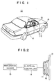
- FIG.1 is a perspective view of an air bag system 10.
- the air bag system 10 shown in FIG.1 has an inflater 11 and a bag 12 placed in the center portion of a steering wheel 13.
- the air bag system 10 also has an electrical control unit 14 and a deceleration sensor 15.
- FIG.2 is a block diagram of the air bag system 10. As shown in FIG.2, the deceleration sensor 15 is connected with the electrical control unit 14. The electrical control unit 14 is connected with the inflater 11.
- the deceleration sensor 15 detects a deceleration exerted on the automobile.
- the electrical unit 14 detects a collision of an automobile in accordance with deceleration signals supplied by the deceleration sensor 15. When a deceleration larger than a predetermined level is detected by the deceleration sensor 15, the electrical control unit 14 judges that a collision of an automobile has occurred, and generates a control signal for operating the air bag system 10.
- the inflater 11 releases a gas when it receives the control signal. Thus, the bag 12 is inflated by the gas.
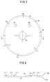
- FIG.3 shows an underside base cloth 16 and an upperside base cloth 17 stacked so that the respective front sides are in contact each other.
- FIG.4 shows a cross-sectional view taken along a line IV-IV in FIG. 3.
- the bag 12 of the present embodiment includes the underside base cloth 16 and the upperside base cloth 17.
- the underside base cloth 16 and the upperside base cloth 17 are made of, for example, nylon or polyester.
- the reverse sides of the cloths 16 and 17 are coated with a heat-resistant rubber.
- the underside base cloth 16 has a gas inlet 18, which receives the inflating gas when the air bag system is operated.
- the underside base cloth 16 also has two gas outlets 19 through which the gas supplied to the bag 12 may flow out and permit the bag to deflate,
- FIG.3 and FIG.4 show the structure of the air bag during an intermediate step in the manufacturing method and which is after completing the steps of forming a body of the bag 12 and forming auxiliary bags in the process of manufacturing the bag 12.
- the underside base cloth 16 and the upperside base cloth 17 are stitched together along a line 20 substantially concentric to the inlet 18 along a periphery of the cloths 16 and 17.
- the stitch line 20 has sufficient resistance against tension exerted thereon to remain intact when the air bag system is actuated and the air bag is filled with gas.
- the two cloths 16 and 17 remain stitched together.
- the underside base cloth 16 and the upperside base cloth 17 are also stitched together along lines 22 and 24.
- the stitch lines 22 and 24 are positioned so as to be substantially parallel. Each end of each stitch lines 22 and 24 intersects the stitch line 20.
- the stitch line 20 is substantially circular and the stitch line 22 and 24 intersect the stitch line 20 so as to define first and second substantially arc-shaped auxiliary bags 26 and 28.
- the stitch lines 22 and 24 are less resistant to the force exerted by the gas than the stitch line 20.
- the stitch lines 22 and 24 are broken when the tension exerted thereon becomes greater than a predetermined level in the inflation process of the bag 12.
- the bag 12 is in the reverse state as compared to the state of the bag 12 when it is inflate.
- the cloths 16 and 17 form the aforementioned bag body.
- auxiliary bags 26 and 28 are defined by the stitch line 20 and the stitch lines 22 and 24.
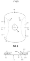
- FIG.5 shows the original state of the bag 12 after the reversal step described above.
- FIG.6 is a cross-sectional view taken along a line VI-VI in FIG.5.
- the bag 12 has the auxiliary bags 26 and 28 located interiorly of where the stitch line 20 is located.
- the outer edges 16a, 17a of the underside base cloth 16 and the upperside base cloth 17 are located within the bag 12 together with the auxiliary bags 26 and 28 wherein the outer edges 16a, 17a are positioned closer to the gas inlet 18 than the auxiliary bags 26 and 28.
- the bag 12 thus formed is folded in a suitable size. Then, the folded bag 12 is set in, for example, the center of the steering wheel 13 with the gas inlet 18 connected to the inflater 11 also provided in the steering wheel 13.
- the bag 12 When an inflating gas is supplied to the bag 12 from the inflater 11, the bag 12 starts inflating. At the beginning of the inflation, the auxiliary bag 26 and 28 do not expand due to the resistance of the stitch lines 22 and 24. Therefore, the volume of the bag 12 measured at the beginning of the inflation is equal to a volume obtained by subtracting the volume of the auxiliary bags 26 and 28 from the whole volume of the bag 12.
- the bag 12 has a relatively small volume during the initial stage of the inflation to restrain the driver precisely .
- the bag 12 has a relatively large volume to prevent various type and degree of forces from various directions being exerted on the driver.
- the auxiliary bags 26 and 28 are formed and positioned interiorly of the bag 12 as has been previously described with the stitch lines 22 and 24 being less than that of the stitch line 20.
- the bag 12 is a component of the air bag system which instantaneously inflates the bag.
- the friction is not favorable to efficient operation of the air bag.
- the edges of the underside base cloth 16 and the uppreside base cloth 17 should be located within the bag 12.
- FIG.7 and FIG.8 show a prior art bag 30.
- the edges of the underside base cloth 16 and the upperside base cloth 17 are located within the bag 30, while the auxiliary bags 26 and 28 are exposed.
- the bag 30 is satisfactory for an use in air bag system.
- the bag 12 of the present embodiment can provide for increased production over the bag 30 shown in FIG.7 and FIG.8.
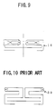
- FIG.9 shows an installed state of the bag 12
- FIG.10 shows an installed state of the bag 30.
- the bag 12 can be folded in a suitable size by folding it once.
- FIG.10 it is necessary to fold the bag 30 twice to reduce it to suitable size. This means that the bag 12 of the present embodiment can be more quickly installed in the automobile so as to provide increased production when compared to the bag 30 in the installing process.
- the first step - the step of forming the stitch line 20, and the second step - the step of forming the stitch lines 22 and 24, are both performed when the cloths 16 and 17 are arranged in stacked form.
- the first and second steps can be processed on the same work table.
- the first embodiment of the present invention is advantageous to the conventional method in which the step of forming the auxiliary bags must be performed after the main bag is formed. Hence, manufacture of the present invention is superior, for increasing production, to that of the conventional method.
- stitch lines 22 and 24 are formed after forming stitch line 20 in the description given previously, the present embodiment is not limited to the above sequence. For example, it is possible to form the stitch line 20 after forming the stitch lines 22 and 24 or to form the stitch line 20 and the stitch lines 22 and 24 simultaneously.
- stitching has been described as a means for joining or securing the underside base cloth 16 and the upperside base cloth 17 together, the invention is not limited to stitching.
- bonding or welding can be used instead of stitching.
- the stitch line 20 is formed, for instance, by a thread having a strength different from the strength of a thread used to form stitch lines 22 and 24.
- different bonding conditions or welding conditions are set so as to provide a strength differential.
- FIG.11 shows a plan view of a bag 40 which has a gas inlet 18 in the center thereof and four auxiliary bags 41, 42, 43 and 44 around the gas inlet 18.
- the bag 40 shown in FIG.10 can be structured by forming four stitch lines 45, 46, 47 and 48 instead of forming two stitch lines 22 and 24.
- the bag 40 is smaller than the bag 12.
- the folding process of the bag 40 is easier than that of the bag 12.
- FIG.12 shows a plan view of a bag 50 manufactured by a manufacturing method according to another embodiment of the present invention.
- the shape drawn with a dotted line indicates the edge of the auxiliary bag 52 which is located interiorly of the bag 50.
- a shape 52' drawn with alternate long and short dash lines indicates the edge of the auxiliary bag 52 when it is in the inflated state.
- the bag 50 has a comparatively larger volume than the bag 12.
- a stitch line 54 forming the edges of the bag 50 and a stitch line 56 separating the auxiliary bag 52 from a main portion of the bag 50 are made so that the main portion of the bag 50 has a volume almost the same as that of the bag 12 shown in FIG.3.
- the bag 50 inflates almost the same way as the bag 12 at the beginning of the inflation.
- the gas pressure in the bag 50 reaches a threshold value, the auxiliary bag 52 starts expanding.
- the bag 50 has an increased volume which is larger than that of the bag 12 at the end of the inflation. With the bag 50, it becomes possible to more effectively restrain the occupants of the automobile in the end stage of the inflation.
- the bag 50 has a sufficient volume after expanding, it is not necessary to provide the bag 50 with a gas outlet such as shown in FIG.3. Thus, use of the bag 50 facilitates production and avoids a situation in which gas leaks out to the interior of the vehicle.
- the bag 50 is manufactured as follows. First, the underside base cloth 57 and the upperside base cloth 58 are stitched together along a periphery of the cloths 57 and 58 so that a stitch line 54 is formed. After that, the underside base cloth 57 and the upperside base cloth 58 are also stitched together so that the stitch line 56 is formed. Then, the underside base cloth 57 and the uppreside base cloth 58 are turned inside out by pulling the cloth 58 through the gas inlet 59.
- the another auxiliary bag may appropriately control the shape of the bag 50 in the initial stage of the inflation of the bag 50 like the auxiliary bags 26, 28 shown in FIG.5.
- the bag 50 has such another auxiliary bag, the safety of the automobile at the initial stage of inflation of the bag 50 can be more improved.
Landscapes
- Engineering & Computer Science (AREA)
- Mechanical Engineering (AREA)
- Air Bags (AREA)
Claims (8)
- Ein Verfahren zur Herstellung eines Sackes für ein Airbag System, wobei das Verfahren die folgenden Schritte aufweist:(a) Aufeinanderschichten eines ersten Basisstoffes (16; 57) und eines zweiten Basisstoffes (17; 58);(b) Erzeugen eines Hauptsackes durch miteinander Befestigen des ersten Basisstoffes (16; 57), der einen Gaseinlaß (18; 59) hat, und des zweiten Basisstoffes (17; 58) entlang eines Umfangs davon;(c) Erzeugen von mindestens einem Hilfssack (26, 28; 41, 42, 43, 44; 52), indem beide Stoffe entlang mindestens einer Linie (22, 24; 45, 46, 47, 48; 56) quer über die Stoffe miteinander befestigt werden; und(d) Wenden des ersten Basisstoffes und des zweiten Basisstoffes von innen nach außen über den Gaseinlaß nach dem Erzeugen des Hauptsackes und des mindestens einen Hilfssackes (26, 28; 41, 42, 43, 44; 52), so daß mindestens ein Hilfssack (26, 28; 41, 42, 43, 44; 52) im Inneren des Hauptsackes angeordnet werden kann.
- Ein Verfahren gemäß Anspruch 1, dadurch gekennzeichnet, daß die Befestigungsschritte durch zusammennähen von beiden Stoffen (16, 17; 57, 58) durchgeführt werden.
- Ein Verfahren gemäß Anspruch 1, dadurch gekennzeichnet, daß die Befestigungsschritte durch Verkleben beider Stoffe (16, 17; 57, 58) durchgeführt werden.
- Ein Verfahren gemäß Anspruch 1, dadurch gekennzeichnet, daß die Befestigungsschritte durch Verschweißen beider Stoffe (16, 17; 57, 58) durchgeführt werden.
- Ein Verfahren gemaß Anspruch 1, dadurch gekennzeichnet, daßder Schritt (b) zur Erzeugung des Hauptsackes so durchgeführt wird, daß der Umfang eine erste Reißfestigkeit hat; unddaß der Schritt (c) zur Erzeugung von mindestens einem Hilfssack so durchgeführt wird, daß die Nahtlinie (22, 24; 45, 46, 47, 48; 56) zur Befestigung so durchgeführt wird, daß sie eine zweite Reißfestigkeit hat, die geringer ist, als die erste Reißfestigkeit.
- Ein Verfahren gemäß Anspruch 5, dadurch gekennzeichnet, daßder Schritt (b) zur Erzeugung des Hauptsackes einen Schritt zum Vernähen beider Stoffe (16, 17; 57, 58) durch ein erstes Garn mit einer vorbestimmten Reißfestigkeit enthält; unddaß der Schritt (c) zu Erzeugung von mindestens einem Hilfssack einen Schritt zur Vernähung beider Stoffe (16, 17; 57, 58) durch ein zweites Garn, das eine vorbestimmte Reißfestigkeit hat, die geringer ist, als diejenige des ersten Garns, enthält.
- Ein Sack für ein Airbag System, der durch die Schritte von irgendeinem der vorherigen Ansprüche hergestellt wird.
- Verwendung eines Airbags gemäß Anspruch 7 in einem Airbag System, aufweisendeine Beschleunigungsabnahmeerfassungseinheit (15) zur Erfassung der Beschleunigungsabnahme, die auf ein Fahrzeug ausgeübt wird;eine Steuereinheit (14) zur Erzeugung eines Steuersignals, wenn die Beschleunigungsabnahmeerfassungseinheit (15) eine Beschleunigungsabnahme erfaßt, die größer als ein vorbestimmter Pegel ist; undeine Gasfreigabeeinheit (11) zur Freigabe eines Gases, wenn sie das Steuersignal empfängt.
Applications Claiming Priority (2)
| Application Number | Priority Date | Filing Date | Title |
|---|---|---|---|
| JP06127626A JP3115477B2 (ja) | 1994-06-09 | 1994-06-09 | エアバッグ袋体の製造方法 |
| JP127626/94 | 1994-06-09 |
Publications (2)
| Publication Number | Publication Date |
|---|---|
| EP0686527A1 EP0686527A1 (de) | 1995-12-13 |
| EP0686527B1 true EP0686527B1 (de) | 1999-01-13 |
Family
ID=14964744
Family Applications (1)
| Application Number | Title | Priority Date | Filing Date |
|---|---|---|---|
| EP95108839A Expired - Lifetime EP0686527B1 (de) | 1994-06-09 | 1995-06-08 | Sack für ein Luftsacksystem und sein Herstellungsverfahren |
Country Status (4)
| Country | Link |
|---|---|
| US (1) | US5599040A (de) |
| EP (1) | EP0686527B1 (de) |
| JP (1) | JP3115477B2 (de) |
| DE (1) | DE69507202T2 (de) |
Cited By (1)
| Publication number | Priority date | Publication date | Assignee | Title |
|---|---|---|---|---|
| WO2016008708A1 (de) | 2014-07-16 | 2016-01-21 | Takata AG | Gassack für ein fahrzeuginsassen-rückhaltesystem |
Families Citing this family (21)
| Publication number | Priority date | Publication date | Assignee | Title |
|---|---|---|---|---|
| GB2310171B (en) * | 1996-02-19 | 2000-06-28 | Airbags Int Ltd | Improvements in or relating to an air-bag with breakable seams |
| JPH09323605A (ja) * | 1996-03-27 | 1997-12-16 | Morton Internatl Inc | 自動車の乗客室内の占有者を保護する方法とエアバッグクッションを折りたたむ方法 |
| JP3769831B2 (ja) * | 1996-04-08 | 2006-04-26 | タカタ株式会社 | エアバッグ及びエアバッグ装置 |
| JPH106899A (ja) * | 1996-04-26 | 1998-01-13 | Nippon Plast Co Ltd | エアバッグ装置およびエアバッグの折畳方法 |
| JPH09301104A (ja) * | 1996-05-17 | 1997-11-25 | Kansei Corp | サイドエアバッグ装置のエアバッグ構造 |
| US5871231A (en) * | 1996-06-05 | 1999-02-16 | Simula Inc. | Low aggressivity variable-volume variable-inflation air bag system |
| GB2314298B (en) * | 1996-06-17 | 2000-08-09 | Autoliv Dev | Improvements in or relating to a triangular folding bag |
| US5732973A (en) * | 1996-07-22 | 1998-03-31 | Trw Vehicle Safety Systems Inc. | Tuck folded air bag |
| DE29801051U1 (de) * | 1998-01-22 | 1998-05-20 | Trw Repa Gmbh | Gassack für eine Seitenaufprall-Schutzeinrichtung |
| JPH11255063A (ja) * | 1998-03-13 | 1999-09-21 | Takata Kk | エアバッグ及びエアバッグ装置 |
| DE29813082U1 (de) * | 1998-07-22 | 1998-11-19 | TRW Occupant Restraint Systems GmbH & Co. KG, 73553 Alfdorf | Gassack-Rückhaltesystem |
| US6962363B2 (en) * | 2000-07-07 | 2005-11-08 | Milliken & Company | Multiple chamber airbags and methods |
| US6547709B1 (en) * | 2000-08-23 | 2003-04-15 | Breed Automotive Technology, Inc. | Method of folding an air bag |
| DE20113191U1 (de) * | 2001-08-09 | 2001-10-25 | Autoliv Dev | Aufblasbarer Gassack (Airbag) |
| US7401811B2 (en) * | 2003-09-10 | 2008-07-22 | Honda Motor Co., Ltd. | Airbag device |
| JP4807004B2 (ja) * | 2004-12-22 | 2011-11-02 | タカタ株式会社 | エアバッグ装置 |
| JP5049660B2 (ja) * | 2007-06-11 | 2012-10-17 | 本田技研工業株式会社 | エアバッグ装置 |
| KR101033788B1 (ko) * | 2008-10-14 | 2011-05-13 | 기아자동차주식회사 | 차량 운전석의 에어백쿠션 및 그 폴딩방법 |
| DE102009056860A1 (de) | 2009-11-10 | 2011-05-12 | GM Global Technology Operations LLC, Detroit | Frontalairbageinrichtung für ein Fahrzeug |
| US20110260436A1 (en) * | 2010-04-27 | 2011-10-27 | Park Hae Kwon | Passenger airbag apparatus |
| JP2015160586A (ja) * | 2014-02-28 | 2015-09-07 | 住商エアバッグ・システムズ株式会社 | エアバッグ |
Family Cites Families (10)
| Publication number | Priority date | Publication date | Assignee | Title |
|---|---|---|---|---|
| DE2745620A1 (de) * | 1977-10-11 | 1979-04-12 | Daimler Benz Ag | Luftsack-system zum schutz der insassen eines kraftfahrzeuges bei unfaellen |
| IT8884959A0 (it) * | 1988-07-28 | 1988-07-28 | Italclimax Srl | Apparecchiatura integrata per la produzione di acqua calda. |
| JPH0367748A (ja) * | 1989-08-08 | 1991-03-22 | Toyoda Gosei Co Ltd | エアバツグ装置におけるエアバツグ |
| JPH03136945A (ja) * | 1989-10-24 | 1991-06-11 | Ikeda Bussan Co Ltd | エアバッグ装置 |
| JPH03182854A (ja) * | 1989-12-12 | 1991-08-08 | Toray Ind Inc | エアーバッグ |
| DE4124506A1 (de) * | 1991-07-24 | 1993-01-28 | Daimler Benz Ag | Aufblasbares aufprallschutzkissen |
| GB2263668B (en) * | 1992-01-28 | 1995-02-01 | Autoliv Dev | Improvements in or relating to an air bag arrangement |
| US5358273A (en) * | 1992-03-09 | 1994-10-25 | Toyo Tire & Rubber Co., Ltd. | Inflatable bags for airbag passive restraint systems for driver and method for production thereof |
| JP2629531B2 (ja) * | 1992-08-28 | 1997-07-09 | 池田物産株式会社 | エアバッグ装置のエアバッグ本体 |
| US5454595A (en) * | 1994-09-08 | 1995-10-03 | Morton International, Inc. | Hidden volume cushion |
-
1994
- 1994-06-09 JP JP06127626A patent/JP3115477B2/ja not_active Expired - Fee Related
-
1995
- 1995-06-01 US US08/457,277 patent/US5599040A/en not_active Expired - Fee Related
- 1995-06-08 DE DE69507202T patent/DE69507202T2/de not_active Expired - Fee Related
- 1995-06-08 EP EP95108839A patent/EP0686527B1/de not_active Expired - Lifetime
Cited By (1)
| Publication number | Priority date | Publication date | Assignee | Title |
|---|---|---|---|---|
| WO2016008708A1 (de) | 2014-07-16 | 2016-01-21 | Takata AG | Gassack für ein fahrzeuginsassen-rückhaltesystem |
Also Published As
| Publication number | Publication date |
|---|---|
| EP0686527A1 (de) | 1995-12-13 |
| US5599040A (en) | 1997-02-04 |
| JPH07329664A (ja) | 1995-12-19 |
| JP3115477B2 (ja) | 2000-12-04 |
| DE69507202D1 (de) | 1999-02-25 |
| DE69507202T2 (de) | 1999-07-08 |
Similar Documents
| Publication | Publication Date | Title |
|---|---|---|
| EP0686527B1 (de) | Sack für ein Luftsacksystem und sein Herstellungsverfahren | |
| US6969086B2 (en) | Airbag and airbag device | |
| JP3626529B2 (ja) | エアバッグ装置の製造方法 | |
| US5048863A (en) | Anti-collision cushion for the occupants of a motor vehicle | |
| EP0838377B1 (de) | Airbag-Bewegungsbegrenzungsband | |
| US5979937A (en) | Air bag device | |
| EP1514743B1 (de) | Airbagvorrichtung | |
| US6962366B2 (en) | Air bag device | |
| US5833265A (en) | Airbag with excursion restrictors | |
| US20040155440A1 (en) | Airbag and airbag apparatus | |
| EP0787673B1 (de) | Gefalteter Luftsack und Verfahren zur Faltung eines Luftsackes | |
| EP0771694A2 (de) | Airbag-Bewegungsbegrenzungsband und seine Verbindung | |
| JP2001301556A (ja) | エアバッグ装置 | |
| JPH08198049A (ja) | エアバッグ及びエアバッグ取付構造 | |
| JPH06234344A (ja) | 膨らみ可能な衝突保護クッション | |
| US5803483A (en) | Airbag cushion and method of folding thereof | |
| JPH11348721A (ja) | エアベルト及びエアベルト装置 | |
| EP1889759B1 (de) | Airbagvorrichtung | |
| JPH08310325A (ja) | 膨張可能な衝撃保護エアバッグクッション及びその製造方法 | |
| JP2668332B2 (ja) | 助手席用エアバッグ装置 | |
| US8191926B2 (en) | Inflatable airbag assembly with an airbag housing vent panel | |
| EP0693403A2 (de) | Aufblasbares Fahrzeuginsassen-Rückhaltegaskissen | |
| CN101081613A (zh) | 气囊装置 | |
| JP2005153726A (ja) | エアバッグ及びエアバッグ装置 | |
| EP1577171B1 (de) | Airbagvorrichtung |
Legal Events
| Date | Code | Title | Description |
|---|---|---|---|
| PUAI | Public reference made under article 153(3) epc to a published international application that has entered the european phase |
Free format text: ORIGINAL CODE: 0009012 |
|
| 17P | Request for examination filed |
Effective date: 19950608 |
|
| AK | Designated contracting states |
Kind code of ref document: A1 Designated state(s): DE FR GB |
|
| 17Q | First examination report despatched |
Effective date: 19961127 |
|
| GRAG | Despatch of communication of intention to grant |
Free format text: ORIGINAL CODE: EPIDOS AGRA |
|
| GRAG | Despatch of communication of intention to grant |
Free format text: ORIGINAL CODE: EPIDOS AGRA |
|
| GRAH | Despatch of communication of intention to grant a patent |
Free format text: ORIGINAL CODE: EPIDOS IGRA |
|
| GRAH | Despatch of communication of intention to grant a patent |
Free format text: ORIGINAL CODE: EPIDOS IGRA |
|
| GRAA | (expected) grant |
Free format text: ORIGINAL CODE: 0009210 |
|
| AK | Designated contracting states |
Kind code of ref document: B1 Designated state(s): DE FR GB |
|
| ET | Fr: translation filed | ||
| REF | Corresponds to: |
Ref document number: 69507202 Country of ref document: DE Date of ref document: 19990225 |
|
| PLBE | No opposition filed within time limit |
Free format text: ORIGINAL CODE: 0009261 |
|
| STAA | Information on the status of an ep patent application or granted ep patent |
Free format text: STATUS: NO OPPOSITION FILED WITHIN TIME LIMIT |
|
| 26N | No opposition filed | ||
| REG | Reference to a national code |
Ref country code: GB Ref legal event code: IF02 |
|
| REG | Reference to a national code |
Ref country code: GB Ref legal event code: 746 Effective date: 20040505 |
|
| REG | Reference to a national code |
Ref country code: FR Ref legal event code: D6 |
|
| PGFP | Annual fee paid to national office [announced via postgrant information from national office to epo] |
Ref country code: DE Payment date: 20050602 Year of fee payment: 11 |
|
| PGFP | Annual fee paid to national office [announced via postgrant information from national office to epo] |
Ref country code: GB Payment date: 20050608 Year of fee payment: 11 Ref country code: FR Payment date: 20050608 Year of fee payment: 11 |
|
| PG25 | Lapsed in a contracting state [announced via postgrant information from national office to epo] |
Ref country code: GB Free format text: LAPSE BECAUSE OF NON-PAYMENT OF DUE FEES Effective date: 20060608 |
|
| PG25 | Lapsed in a contracting state [announced via postgrant information from national office to epo] |
Ref country code: DE Free format text: LAPSE BECAUSE OF NON-PAYMENT OF DUE FEES Effective date: 20070103 |
|
| GBPC | Gb: european patent ceased through non-payment of renewal fee |
Effective date: 20060608 |
|
| REG | Reference to a national code |
Ref country code: FR Ref legal event code: ST Effective date: 20070228 |
|
| PG25 | Lapsed in a contracting state [announced via postgrant information from national office to epo] |
Ref country code: FR Free format text: LAPSE BECAUSE OF NON-PAYMENT OF DUE FEES Effective date: 20060630 |