EP0689042A2 - Simulator zum Prüfen einer ABS-Anlage - Google Patents
Simulator zum Prüfen einer ABS-Anlage Download PDFInfo
- Publication number
- EP0689042A2 EP0689042A2 EP95304395A EP95304395A EP0689042A2 EP 0689042 A2 EP0689042 A2 EP 0689042A2 EP 95304395 A EP95304395 A EP 95304395A EP 95304395 A EP95304395 A EP 95304395A EP 0689042 A2 EP0689042 A2 EP 0689042A2
- Authority
- EP
- European Patent Office
- Prior art keywords
- pneumatic
- flywheel
- pressure
- flywheels
- wheels
- Prior art date
- Legal status (The legal status is an assumption and is not a legal conclusion. Google has not performed a legal analysis and makes no representation as to the accuracy of the status listed.)
- Withdrawn
Links
- 238000012360 testing method Methods 0.000 title claims abstract description 31
- 238000012544 monitoring process Methods 0.000 claims abstract description 6
- 230000001105 regulatory effect Effects 0.000 claims abstract description 6
- 230000004907 flux Effects 0.000 claims description 13
- 230000001276 controlling effect Effects 0.000 claims description 12
- 238000012546 transfer Methods 0.000 claims description 8
- 230000004044 response Effects 0.000 claims description 5
- 238000007599 discharging Methods 0.000 claims description 2
- 229920000122 acrylonitrile butadiene styrene Polymers 0.000 description 32
- 238000000926 separation method Methods 0.000 description 6
- 238000009434 installation Methods 0.000 description 4
- 239000012141 concentrate Substances 0.000 description 3
- 238000010586 diagram Methods 0.000 description 3
- 230000003247 decreasing effect Effects 0.000 description 2
- 230000000694 effects Effects 0.000 description 2
- 230000009471 action Effects 0.000 description 1
- 238000004458 analytical method Methods 0.000 description 1
- 230000008859 change Effects 0.000 description 1
- 230000007423 decrease Effects 0.000 description 1
- 230000003028 elevating effect Effects 0.000 description 1
- 230000008014 freezing Effects 0.000 description 1
- 238000007710 freezing Methods 0.000 description 1
- 238000000034 method Methods 0.000 description 1
- 238000011056 performance test Methods 0.000 description 1
- 238000012545 processing Methods 0.000 description 1
- 230000000630 rising effect Effects 0.000 description 1
- 238000005096 rolling process Methods 0.000 description 1
Images

Classifications
-
- G—PHYSICS
- G01—MEASURING; TESTING
- G01M—TESTING STATIC OR DYNAMIC BALANCE OF MACHINES OR STRUCTURES; TESTING OF STRUCTURES OR APPARATUS, NOT OTHERWISE PROVIDED FOR
- G01M17/00—Testing of vehicles
- G01M17/007—Wheeled or endless-tracked vehicles
-
- G—PHYSICS
- G01—MEASURING; TESTING
- G01L—MEASURING FORCE, STRESS, TORQUE, WORK, MECHANICAL POWER, MECHANICAL EFFICIENCY, OR FLUID PRESSURE
- G01L5/00—Apparatus for, or methods of, measuring force, work, mechanical power, or torque, specially adapted for specific purposes
- G01L5/28—Apparatus for, or methods of, measuring force, work, mechanical power, or torque, specially adapted for specific purposes for testing brakes
- G01L5/282—Apparatus for, or methods of, measuring force, work, mechanical power, or torque, specially adapted for specific purposes for testing brakes the vehicle wheels cooperating with rotatable rolls
Definitions
- the present invention relates to a simulator for testing an anti-lock braking system (hereinafter simply referred to as "ABS").
- ABS anti-lock braking system
- an ABS is mounted to the vehicle, which employs a hydraulic braking system.
- the locking state denotes that, when a driver suddenly steps on a brake while driving, the rolling motion of the wheels is brought to a halt by the braking system mounted to the respective wheels.
- the inertia force of the vehicle is so large as to exceed a frictional force between the tires and road surface, the vehicle continuously slips along the road in the travelling direction of the vehicle. Due to the slip, the frictional force is further decreased to lengthen the braking distance.
- the frictional force is greatly decreased, the vehicle is unable to be steered, regardless of manipulation of a handle thereof, thereby possibly bringing about a disastrous accident.
- the ABS prevents the locking phenomenon to ensure the stability of straight travelling and the steering performance of the vehicle even in a situation of sudden stoppage by means of automatically controlling the braking pressure of the brake so as to completely achieve braking within the shortest possible distance.
- the ABS is provided with a set of speed sensors for monitoring the speed of respective wheels, and automatically increases, decreases and maintains the hydraulic pressure of the braking in accordance with the monitored speed.
- the preferable method for testing the performance of the ABS is to actually mount the ABS to a vehicle and allow the vehicle to actually travel along a road with different surface conditions, as, for instance, a dry surface, a wet surface, a frozen surface, etc.
- a dry surface a wet surface
- a frozen surface a road with different surface conditions
- various kinds of vehicles are manufactured and diverse options may be added to a single vehicle type with the consequences of high costs, manpower and time to effect the performance tests of all the ABSs available on the market with respect to every kind of vehicle.
- US Patent No. 5,101,660 discloses a dynamometer apparatus for testing two and four wheel drive vehicles under simulated road conditions.
- the apparatus includes a front roll and a rear roll for engaging the front and rear wheels of the vehicle, an electric motor coupled to each roll, a force transducer and a speed sensor coupled to each roll.
- ABS testing apparatuses described as above are constructed to be furnished with a brake test stand, in which, under the state of mounting the ABS to an actually-used vehicle, respective wheels are placed on a pair of front-wheel driving rollers and a pair of rear-wheel driving rollers allotted to the respective front wheels and rear wheels or on pairs of driving rollers allotted to four wheels, and these pairs of driving rollers are driven to operate the ABS for testing the performance thereof.
- a testing apparatus cannot simulate various travelling conditions, eg, the yawing of the wheels and the disproportionate concentration of the vehicle weight, making it impossible to evaluate accurate performance of the ABS.
- driving motors are supplied to respective pairs of driving rollers for driving the wheels, thereby increasing installation costs.
- most of the testing apparatuses are incorporated between the driving motor and pairs of driving rollers, with a sliding-control member, eg, an electronic clutch, for controlling a sliding characteristic between the wheels and driving roller pairs, which also induces the increase of installation costs.
- a simulator for testing an anti-lock braking system comprising first and second rotatable wheels, first and second rotatable flywheels arranged to contact said first and second rotatable wheels, and flywheel driving means for rotating said first and second flywheels, wherein said flywheel driving means is arranged to selectively rotate said first and second flywheels at the same speed or at different speeds.
- a simulator of an embodiment of the invention is able to simulate yawing of the vehicle and/or simulate a disproportionate concentration of vehicle weight on a wheel of the vehicle.
- said simulator further comprises control means for said flywheel driving means, and sensors for sensing parameters of said simulator and/or of the system under test, wherein said control means is responsive to said sensors.
- control means is responsive to speed sensors monitoring the rotational speed of the or each flywheel.
- said simulator further comprises means for maintaining a predetermined pressure between each flywheel and the associated rotatable wheel.
- said pressure maintaining means is arranged selectively to maintain the same pressure or different pressures between each flywheel and its associated rotatable wheel.
- Said simulator may further comprise braking means for applying braking forces to said first and second rotatable wheels.
- said braking means is arranged to mount an anti-lock braking system modulator to be tested, and wherein said braking means is arranged selectively to apply the same or different braking forces to each of said rotatable wheels.
- the present invention also provides a simulator for testing an ABS modulator including rotatable opposing first and second flywheels in contact with a pair of wheels by a first predetermined pressure, and a flywheel driving portion which transfers a driving force to the first and second flywheels, and manages (controls the transfer and stoppage of) the driving force with respect to the first and second flywheels and/or the driving force with respect to the second flywheel.
- wheel rotation-speed sensors monitor the rotational speed of the pair of wheels
- flywheel rotation-speed sensors monitor the rotational speed of the first and second flywheels.
- a wheel pressing unit respectively installed to the pair of wheels maintains a contact pressure between the wheel and flywheel by the predetermined pressure to allow a frictional force between the wheel and flywheel to concur with a frictional force between a tire and a road surface.
- a braking system generates a second predetermined pressure equivalent to the pressure induced by a driver stepping on a brake pedal, generates a braking force corresponding to the second predetermined pressure, transfers the braking force to the wheels, and then mounts a modulator to be tested thereon.
- a pneumatic pressure generator supplies the second predetermined pressure to the braking system and wheel pressing unit, and a controller electrically connected to the flywheel driving portion, wheel rotation-speed sensors, flywheel rotation-speed sensors, and pneumatic pressure generator, simulates various road surface conditions in accordance with a command, controls the flywheel driving portion to allow the pair of flywheels to have an identical rotational speed or different rotational speeds in response to an input signal from the flywheel rotation-speed sensors, supplies a control signal to the pneumatic pressure generator to provide an identical rotational speed or different rotational speeds to the wheel pressing unit respectively connected to the pair of wheels, and outputs a control signal to the pneumatic pressure generator to operate the braking system.
- the flywheel driving portion may comprise a motor for generating the driving force, a driving shaft forming a rotational shaft of the first and second flywheels for transferring the driving force from the motor to the first and second flywheels, first driving force managing means provided on the driving shaft between the motor and first flywheel for managing the transfer of the driving force, and second driving force managing means provided on the driving shaft between the first and second flywheels for managing the transfer of the driving force to the second flywheel.
- an electromagnetic clutch may be employed.
- pneumatic cylinders may be employed.
- encoders for generating electrical pulses in response to the rotation of the wheels and flywheels may be employed.
- the pneumatic pressure generating circuit may comprise a pneumatic pressure generating portion, a braking pressure supply portion for supplying the second predetermined pneumatic pressure to the braking pressure generating means, and first and second pneumatic pressure supply portions for independently supplying the first predetermined pneumatic pressure to the respective wheel pressing means, wherein the first pneumatic pressure supply portions and braking pressure supply portion are respectively formed of a pneumatic regulator for regulating the pneumatic pressure from the pneumatic pressure generating portion in a predetermined level, a flux controller for controlling flux, and a solenoid valve connected between the pneumatic regulator and a flux controller for switching a path for receiving the pneumatic pressure, and the other of the first and second pneumatic pressure supply portions is formed of a first solenoid valve connected to the pneumatic pressure generating portion for switching the path for receiving the pneumatic pressure, a second solenoid valve connected to the first solenoid valve for switching the pneumatic path of high level or low level, a high-level pneumatic regulator connected to the second solenoid valve for controlling the pneumatic pressure for supplying the pneumatic
- the simulator for testing an ABS modulator according to the invention may further comprise at least one inertia plate detachably fixed to the flywheel to generate the inertia moment identical to the inertia moment of a vehicle weight.
- the braking means comprises braking pressure generating means for supplying the pressure equivalent to the pressure caused by the driver stepping on the brake pedal, a master cylinder for generating a hydraulic pressure for braking the pair of wheels in accordance with the pressure from the braking pressure generating means, and a brake provided to the respective pair of wheels, and the modulator is supplied between the brake and master cylinder.
- the braking pressure generating means may be formed of a pneumatic cylinder.
- a simulator according to the present invention constructed as above is provided with one driving motor and two electronic clutches to economise installation cost over a conventional testing apparatus including four driving motors and four electronic clutches. Also, by altering the inertia moment of the flywheels and the pressure of the wheels against the flywheels, the yawing of vehicles and the disproportionate concentration of the vehicle weight can be simulated under the various vehicle weight to enable the testing of the ABS modulator by setting diverse road surface conditions.
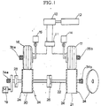
- Figures 1 to 3 show a simulator for testing an ABS modulator, the simulator having first and second flywheels 20 and 21 which are in rotational contact with a pair of wheels 16 and 17 by a predetermined pressure.
- the first and second flywheels 20 and 21 are provided with a flywheel driving portion for transmitting a driving force to the first and second flywheels 20 and 21 and for interrupting the driving force with respect to the first and second flywheels 20 and 21 and/or the second flywheel 21.
- the flywheel driving portion has an electric motor 19, and a driving shaft 22 for transferring the driving force generated from the electric motor 19 to the first and second flywheels 20 and 21 while constituting a rotational shaft of the first and second flywheels 20 and 21.
- a first electronic clutch 23 is installed on the driving shaft 22 between the electric motor 19 and the first flywheel 20, and a second electronic clutch 25 for managing the driving force transferred to the second flywheel 21 is installed on the driving shaft 22 between the first and second flywheels 20 and 21.
- the simulator includes a braking system 38 arranged to generate a pressure which is equivalent to the pressure produced by a driver stepping on a brake pedal.
- the braking system 38 induces a braking force in response to the pressure generated and transmits the braking force to the pair of wheels 16 and 17.
- the braking system 38 is further provided with a first pneumatic cylinder 12 and a master cylinder 13.
- Reference numeral 11 denotes an ABS modulator to be tested.
- the ABS modulator 11 is installed between the master cylinder 13 of the braking system 38 in a vehicle and a wheel cylinder (not shown) attached to the pair of wheels 16 and 17 to regulate the hydraulic pressure supplied to the braking system 38.
- Manual braking is performed by directly driving a piston of the master cylinder 13 by means of the first pneumatic cylinder 12.
- a pneumatic pressure generated by a pneumatic circuit 40 illustrated in Figure 3 is partially supplied to the first pneumatic cylinder 12.
- the hydraulic pressure to be supplied to the braking system 38 is generated from the master cylinder 13.
- the pneumatic pressure is equivalent to the pressure obtained by a driver stepping on the brake pedal.
- the other pneumatic pressure generated by pneumatic circuit 40 is supplied to a second pneumatic cylinder 14 and a third pneumatic cylinder 15 which are wheel pressing apparatus.
- the wheel pressing apparatus is provided to the pair of wheels 16 and 17 for maintaining a contact pressure between the wheels 16 and 17 and the pair of flywheels 20 and 21 by a predetermined pressure.
- the second and third pneumatic cylinders 14 and 15 are mechanically connected to opposing first and second wheels 16 and 17.
- the pneumatic pressure is set to have a pressure value determined by considering the frictional force between the tire and road surface, which is supplied to the first and second wheels 16 and 17.
- the frictional force generally exerted on the wheel is produced proportional to a frictional coefficient between the wheel and road surface and a perpendicular contact force by the vehicle weight.
- the frictional coefficient is not varied but the pressures produced by the second and third pneumatic cylinders 14 and 15 are applied to the first and second wheels 16 and 17 for varying the perpendicular contact force between the first and second wheels 16 and 17 and the first and second flywheels 20 and 21 in the simulator.
- the pressure can be differently set to the second and third pneumatic cylinders 14 and 15 in the simulator for simulating circumstances in which a disproportionate concentration of the vehicle weight is applied to one wheel, caused for example, in actual travel of the vehicle whilst travelling along uneven road surfaces or curved roads.
- the first and second flywheels 20 and 21 function as travelling surfaces of the vehicle in actual travel, contact the first and second wheels 16 and 17 by a predetermined pressure, and are rotated by the rotation of the driving shaft 22 fixed to the first and second flywheels 20 and 21.
- the driving shaft 22 is rotated by the electric motor 19.
- the rotational force originating from the electric motor 19 is transferred to the first and second wheels 16 and 17 via the driving shaft 22 and the first and second flywheels 20 and 21 to rotate the first and second wheels 16 and 17.
- a decelerator may be installed between the electric motor 19 and the driving shaft 22 for permitting first and second flywheels 20 and 21 to be rotated by a predetermined number of revolutions.
- the size and weight of the first and second flywheels 20 and 21 are determined such that the inertia moment of the flywheel corresponds to the inertia moment of the actual vehicle.
- at least one inertia plate 24 may be detachably mounted to the first and second flywheels 20 and 21 to enable the testing of the ABS modulator with respect to various kinds of vehicles having different weights.
- the number of inertia plates to be mounted is determined by considering the inertia moment of the vehicle proportional to the weight of the actual vehicle to which the ABS modulator to be tested is mounted.
- the first electronic clutch 23 is installed onto the driving shaft 22 between the electric motor 19 and the first flywheel 20, and the second electronic clutch 25 is installed onto the driving shaft 22 between the first and second flywheels 20 and 21.
- the first and second electromagnetic clutches 23 and 25 are under normally connected status to each other to transfer the driving force of the electric motor 19 to the first and second flywheels 20 and 21. Once the number of revolutions of the first and second flywheels 20 and 21 reaches a predetermined number of revolutions, the first electromagnetic clutch 23 is opened to initiate the operation of the brake under the state that the electric motor 19 and the first and second flywheels 20 and 21 are separated.
- the second electromagnetic clutch 25 serves to manage the driving force from the electric motor 19 to independently rotate the first and second flywheels 20 and 21.
- the simulator according to one embodiment of the present invention is provided with four speed sensors, ie, the first and second flywheel-speed sensors 34a and 34b and the first and second wheel-speed sensors 35a and 35b, to independently monitor respective rotational speeds of the first and second flywheels 20 and 21 and of the first and second wheels 16 and 17 respectively.
- the first and second flywheel-speed sensors 34a and 34b and the first and second wheel-speed sensors 35a and 35b to independently monitor respective rotational speeds of the first and second flywheels 20 and 21 and of the first and second wheels 16 and 17 respectively.
- any element such as a tacho-generator capable of detecting the rotational speed may be used.
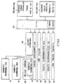
- FIG 2 is a block diagram of the simulator for testing the ABS modulator shown in Figure 1.
- the overall operation of the simulator is controlled by a programmable logic controller (hereinafter referred to as "PLC") 30.
- PLC programmable logic controller
- An input port of the PLC 30 is connected to the first and second flywheel-speed sensors 34a and 34b and the first and second wheel-speed sensors 35a and 35b, and an output port thereof is connected to a flywheel driving portion 32, first electromagnetic clutch 23, second electromagnetic clutch 25, an output unit 36 and a pneumatic circuit 40.
- Figure 3 is a detailed circuit diagram of the pneumatic circuit 40 shown in Figure 2.
- the ABS modulator to be tested is connected between the master cylinder 13 and the wheel cylinder of the simulator, electric power is supplied to the simulator.
- the test conditions eg, set values of the rotational speed of the first and second flywheels 20 and 21, the braking pressure produced by the first pneumatic cylinder 12 for driving the master cylinder 13, and the pneumatic pressure of the second and third pneumatic cylinders 14 and 15, are supplied via the input panel of PLC 30.
- inertia plate 24 in proper numbers is mounted to the flywheel to force the inertia moment of the vehicle created by the weight of the vehicle to which the ABS modulator is actually mounted to concur with the inertia moment of the first and second flywheels 20 and 21.
- An air-compressor driving signal from PLC 30 is supplied into an air-compressor driver 37 to drive an air compressor 39 which can be automatically driven by PLC 30, or manually driven as required.
- a valve switching signal is supplied from PLC 30 to second, third and fourth solenoid valves 46, 48 and 49 to switch them, so that the pneumatic pressure produced from the air compressor 39 is transferred to the second and third pneumatic cylinders 14 and 15.
- the pneumatic pressure transferred to the second and third pneumatic cylinders 14 and 15 the first and second flywheels 20 and 21, and the first and second wheels 16 and 17 come into contact with one another with a predetermined contact pressure.
- the simulator may supply pneumatic pressure at a low level, lower than that of the second pneumatic cylinder 14, to the third pneumatic cylinder 15.
- the valve switching signal transferred from PLC 30 to the third and fourth solenoid valves 48 and 49 is turned off, and the valve switching signal is output to an exhaust solenoid valve 54.
- air is discharged via exhaust solenoid valve 54 during the time preset by a timer 53 to change the pneumatic pressure of the third pneumatic cylinder 13 from high level to low level.
- An electric-motor driving signal from PLC 30 is supplied into flywheel driving portion 32 to rotate the electric motor 19 shown in Figure 1.
- the driving shaft 22 and the first and second flywheels 20 and 21 operatively connected to the electric motor 19 are rotated to rotate the first and second wheels 16 and 17 contacting the first and second flywheels 20 and 21 with a predetermined contact pressure.
- a first clutch separation signal is output from PLC 30 to the first electromagnetic clutch 23 to shift the first electromagnetic clutch 23 from the connection state to the separation state.
- the rotational speed of individual ones of the first and second flywheels 20 and 21 may be independently set in the simulator.
- the second electromagnetic clutch 25 is primarily shifted to the separation state by a second clutch separation signal from PLC 30.
- the first electromagnetic clutch 23 is shifted to the separation state by the first clutch separation signal from PLC 30.
- a braking pressure equivalent to the pressure with which a driver manipulates the brake pedal is generated from the first pneumatic cylinder 12 and directly supplied to the piston of the master cylinder 13, thereby operating the braking system 38. More specifically, once the valve switching signal is output from PLC 30 to the first solenoid valve 43 to switch the first solenoid valve 43, the pneumatic pressure of a predetermined pressure is provided to the first pneumatic cylinder 12. With the pneumatic pressure supplied to the first pneumatic cylinder 12, the braking pressure is transferred to the master cylinder 13 to operate the braking system 38. The magnitude of the braking pressure is regulated by a second pneumatic regulator 42 by a certain pressure.
- the time taken for elevating the braking pressure results from the time required for operating the first solenoid valve 43 and the time delay required until the pressure is formed within the first pneumatic cylinder 12. This braking pressure rising time corresponds to the time delay until the driver steps on the brake pedal in an actual situation.
- Braking system 38 like a general ABS-mounted braking system, includes a brake consisting of the master cylinder 13, the ABS modulator 11, the wheel cylinder, a brake disc and a friction pad.
- the braking pressure in response to the actual manipulation of the brake pedal of the vehicle is generated from the first pneumatic cylinder 12 and supplied to the master cylinder 13, and the hydraulic pressure from the master cylinder 13 is supplied to the wheel cylinder via ABS modulator 11, so that the wheel cylinder presses the friction pad towards the brake disc to effect braking.
- predetermined data such as the speed of the first and second wheels 16 and 17 monitored by the first and second wheel-speed sensors 35a and 35b, the speed of the first and second flywheels 20 and 21 corresponding to the vehicle speed monitored by the first and second flywheel-speed sensors 34a and 34b, the pressure of brake callipers, and the pressure of the master cylinder 13 is supplied to a display unit or output unit 36 which is the printing means.
- the predetermined data is input to a computer via an interface to carry out data processing, output and the like.
- the pneumatic circuit 40 functions as means affording the predetermined braking pressure to the master cylinder 13 in accordance with a control signal of PLC 30, and providing the perpendicular contact force of the first and second wheels 16 and 17 against the first and second flywheels 20 and 21.
- the pneumatic pressure from the air compressor 39 passes through a first pneumatic regulator 41 prior to being supplied to a first pneumatic cylinder 12 via second pneumatic regulator 42, the first solenoid valve 43 and a flux controller 44 to produce the hydraulic pressure to master cylinder 13 shown in Figure 1 which is connected to the piston of the first pneumatic cylinder 12, thereby accomplishing the braking.
- the pneumatic pressure from the first pneumatic regulator 41 is also supplied to second pneumatic cylinder 14 via a third pneumatic regulator 45, the second solenoid valve 46 and a flux controller 47. Therefore, the perpendicular contact force equivalent to the frictional force between the wheel and the ground surface during the actual travelling is generated between the wheel 17 and the flywheel 21.
- Meantime for the purpose of simulating a situation in which the vehicle weight disproportionately concentrates on one wheel when the vehicle actually moves along the uneven portion of a road or along a curved road, it is necessary to supply a pneumatic pressure different from that of the second pneumatic cylinder 14 to the third pneumatic cylinder 15.
- the pneumatic pressure from the first pneumatic regulator 41 is supplied to the third pneumatic regulator 15 via third solenoid valve 48, fourth solenoid valve 49, a fourth pneumatic regulator 50 for regulating the pneumatic pressure to high level, a shuttle valve 52 for selectively opening/closing an output side path of fourth and fifth pneumatic regulators 50 and 51, and a flux controller 55.
- the pneumatic pressure of a low level, lower than that of the second pneumatic cylinder 14, should be supplied to the third pneumatic cylinder 15.
- the valve switching signal from PLC 30 to third and fourth solenoid valves 48 and 49 is turned off to shift the valve position of the third and fourth solenoid valves 48 and 49.
- the pneumatic pressure from the first pneumatic regulator 41 is supplied to the fifth regulator 51 for regulating the pneumatic pressure to the low level, and exhaust solenoid valve 54 is open for the time set by timer 53, so that the pneumatic pressure of the low level, lower than that supplied to the second pneumatic cylinder 14, is provided to the third pneumatic cylinder 15. Consequently, the braking performance of the ABS modulator 11 can be analysed with respect to the situations in which the vehicle weight disproportionately or proportionately concentrates on one wheel.
- the pneumatic circuit utilised in the simulator is not limited to the pneumatic circuit shown in Figure 3, but any type capable of performing the above-stated operation may be utilized.
- a simulator as described and illustrated which has a single driving motor and two electromagnetic clutches can reduce installation costs as compared with the conventional testing apparatus which has four driving motors and four electromagnetic clutches.
- the inertia moment of the flywheel is variable by means of the proper number of inertia plates, enabling the performance testing of the ABS with respect to diverse kinds of vehicles.
- the second and third pneumatic cylinders are employed to identically or differently set the pressure supplied to the pair of flywheels corresponding to the pair of wheels, the yawing of the vehicle and disproportionate concentration of the vehicle weight can be simulated.
- the ABS modulator can be tested by setting various road surface conditions to facilitate the comparison of the objective performance with respect to various ABSs available on the market.
Landscapes
- Physics & Mathematics (AREA)
- General Physics & Mathematics (AREA)
- Regulating Braking Force (AREA)
- Maintenance And Management Of Digital Transmission (AREA)
Applications Claiming Priority (2)
| Application Number | Priority Date | Filing Date | Title |
|---|---|---|---|
| KR9414133 | 1994-06-22 | ||
| KR1019940014133A KR0150481B1 (en) | 1994-06-22 | 1994-06-22 | Simulator of abs (anti-lock brake system) modulator |
Publications (2)
| Publication Number | Publication Date |
|---|---|
| EP0689042A2 true EP0689042A2 (de) | 1995-12-27 |
| EP0689042A3 EP0689042A3 (de) | 1996-05-29 |
Family
ID=19385830
Family Applications (1)
| Application Number | Title | Priority Date | Filing Date |
|---|---|---|---|
| EP95304395A Withdrawn EP0689042A3 (de) | 1994-06-22 | 1995-06-22 | Simulator zum Prüfen einer ABS-Anlage |
Country Status (13)
| Country | Link |
|---|---|
| US (1) | US5621168A (de) |
| EP (1) | EP0689042A3 (de) |
| JP (1) | JPH0840247A (de) |
| KR (1) | KR0150481B1 (de) |
| CN (1) | CN1121585A (de) |
| AU (1) | AU685290B2 (de) |
| BR (1) | BR9508078A (de) |
| CA (1) | CA2193353A1 (de) |
| CZ (1) | CZ374296A3 (de) |
| IL (1) | IL114280A0 (de) |
| PL (1) | PL317992A1 (de) |
| SK (1) | SK162796A3 (de) |
| WO (1) | WO1995035489A1 (de) |
Cited By (7)
| Publication number | Priority date | Publication date | Assignee | Title |
|---|---|---|---|---|
| DE10123828C1 (de) * | 2001-05-16 | 2002-10-17 | Audi Ag | Zwei-Stationen-Schwungmassenbremsenprüfstand |
| FR2842302A1 (fr) * | 2002-07-12 | 2004-01-16 | Renk Ag | Dispositif et procede de simulation de glissement sur des bancs de test de vehicules |
| CN100420931C (zh) * | 2004-06-01 | 2008-09-24 | 北京理工大学 | 基于制动器惯性试验的汽车制动防抱死装置实验台 |
| US7890240B2 (en) * | 2007-04-26 | 2011-02-15 | GM Global Technology Operations LLC | Brake system fault pedal gain change method and system |
| WO2011157343A1 (de) * | 2010-06-18 | 2011-12-22 | Horiba Europe Gmbh | Bremsenprüfstand mit elektrischem bremsaktuator |
| CN103344424A (zh) * | 2013-06-27 | 2013-10-09 | 中国重型机械研究院股份公司 | 通风盘式制动器电惯量模拟试验台及其电惯量模拟控制方法 |
| EP4059793A1 (de) * | 2021-03-17 | 2022-09-21 | Sherpa Autodiagnostik GmbH | Bremsprüfeinrichtung für ein fahrzeug mit mindestens einer antreibbaren achse und verfahren |
Families Citing this family (28)
| Publication number | Priority date | Publication date | Assignee | Title |
|---|---|---|---|---|
| US6895835B2 (en) * | 2000-09-19 | 2005-05-24 | Alan M. Cordeiro | Method of improving performance in a motor-driven system |
| KR100391102B1 (ko) * | 2000-12-07 | 2003-07-12 | 주식회사 에스엠바이오 | 분뇨 비료 |
| KR100436595B1 (ko) * | 2001-03-16 | 2004-06-18 | 주식회사 만도 | 에이비에스 모듈레이터의 누설 검사장치 |
| US6837165B2 (en) * | 2001-11-09 | 2005-01-04 | Olin Corporation | Bullet with spherical nose portion |
| EP1495434B1 (de) | 2002-04-05 | 2018-02-28 | Konstantin Sizov | Tragbarer fahrzeuginterner strassensimulator |
| DE102004031875A1 (de) * | 2004-04-22 | 2005-11-17 | Zf Friedrichshafen Ag | Deckel für eine Luftfeder |
| JP5276656B2 (ja) * | 2008-05-23 | 2013-08-28 | ボッシュ株式会社 | 内部パラメータの自動キャリブレーション機能付きの車両用abs制御装置 |
| KR101629528B1 (ko) * | 2008-09-08 | 2016-06-21 | 버크 이. 포터 머쉬너리 컴퍼니 | 차량 검사 조립체 |
| CN101793610B (zh) * | 2010-02-26 | 2011-12-21 | 中国农业大学 | 一种汽车abs/ebd综合试验系统 |
| US8590369B2 (en) | 2010-12-23 | 2013-11-26 | Horiba Instruments, Inc. | Vehicle drivetrain test stand and method of controlling same |
| US8631693B2 (en) | 2010-12-23 | 2014-01-21 | Horiba Instruments, Inc. | Wheel slip simulation systems and methods |
| US9168906B2 (en) | 2011-03-18 | 2015-10-27 | Bridgestone Americas Tire Operations, Llc | Method of analyzing stopping distance performance efficiency |
| CN102607861A (zh) * | 2012-03-05 | 2012-07-25 | 广州市科密汽车制动技术开发有限公司 | 一种abs系统模拟检测装置 |
| US9589485B2 (en) * | 2012-10-22 | 2017-03-07 | Ramon Elder | Interactive brake display system |
| CN103308236B (zh) * | 2013-05-28 | 2014-11-26 | 吉林大学 | 汽车台架制动力检测车轮约束装置 |
| CN104849064A (zh) * | 2014-12-19 | 2015-08-19 | 北汽福田汽车股份有限公司 | 用底盘测功机对车辆试验的方法及其转鼓附着力调整方法 |
| CN107139915B (zh) * | 2017-06-06 | 2023-04-21 | 安徽农业大学 | 一种车辆气压防抱死性能的测试系统 |
| CN107939765A (zh) * | 2017-12-22 | 2018-04-20 | 万向钱潮股份有限公司 | 电子稳定控制系统无背压功能测试装置 |
| CN108827656A (zh) * | 2018-08-01 | 2018-11-16 | 北京长城华冠汽车技术开发有限公司 | 一种用于模拟整车状态测量制动系统性能的工装 |
| KR102210753B1 (ko) * | 2019-08-09 | 2021-02-02 | 넥센타이어 주식회사 | 타이어 관성 모멘트 측정장치 |
| CN110879153B (zh) * | 2019-12-02 | 2021-05-07 | 河北恒昇机械科技有限公司 | 一种汽车模拟启动和刹车安全检测装置 |
| US11485344B1 (en) * | 2020-02-11 | 2022-11-01 | Robert Dawson, Sr. | Anti-skid braking system diagnostic tool |
| GB2597093A (en) * | 2020-07-15 | 2022-01-19 | Airbus Operations Ltd | Cross-connection test for aircraft landing gear |
| CN112781895B (zh) * | 2021-02-02 | 2021-09-28 | 山东正能汽车检测装备有限公司 | 集成汽车排放及汽车综合安全性能检验平台 |
| KR102384080B1 (ko) * | 2021-07-06 | 2022-04-08 | 근로복지공단 | 전동 보조기기의 주행 신뢰성 실증 테스트 방법 |
| KR102413586B1 (ko) * | 2021-07-06 | 2022-06-28 | 근로복지공단 | 전동 보조기기의 주행 신뢰성 실증 테스트 장치 |
| US11726005B2 (en) * | 2021-09-24 | 2023-08-15 | GM Global Technology Operations LLC | Pressure controlled auto braking for dynamic vehicle test (DVT) |
| CN116893066B (zh) * | 2023-09-11 | 2024-02-06 | 天润通成汽车技术服务(盐城)有限公司 | 一种原地汽车制动检测装置 |
Citations (1)
| Publication number | Priority date | Publication date | Assignee | Title |
|---|---|---|---|---|
| US5101660A (en) | 1991-04-05 | 1992-04-07 | Clayton Industries | Method and apparatus for enabling two or four wheel drive vehicles to be tested under simulated road conditions |
Family Cites Families (10)
| Publication number | Priority date | Publication date | Assignee | Title |
|---|---|---|---|---|
| US3982429A (en) * | 1973-07-25 | 1976-09-28 | Clayton Manufacturing Company | Computer type brake analyzer |
| US3905225A (en) * | 1974-02-20 | 1975-09-16 | Romeyn K Moss | Vehicle testing apparatus and method |
| US4050299A (en) * | 1975-03-06 | 1977-09-27 | Maxwell Lloyd R | Brake testing method |
| HU181369B (en) * | 1981-07-22 | 1983-07-28 | Rudolf Koos | Method and device for measuring brake effect of vehicle in particular, deceleration of brake |
| NL8700401A (nl) * | 1987-02-17 | 1988-09-16 | Sun Electric Systems Bv | Werkwijze en inrichting voor het beproeven van een antiblokkeersysteem (abs) van een motorvoertuig. |
| DE3922570C2 (de) * | 1988-09-29 | 1994-01-13 | Rhein Westfael Tech Ueberwach | Prüfstand für Kraftfahrzeuge, insbes. Bremsprüfstand für Fahrzeuge mit ABS-Bremsanlagen |
| DE3932647A1 (de) * | 1989-09-29 | 1991-04-11 | Siemens Ag | Verfahren zum simulieren des durchrutschvorganges von raedern auf pruefstaenden |
| DE4028561A1 (de) * | 1990-09-08 | 1992-03-12 | Iveco Magirus | Verfahren und vorrichtung zur statischen pruefung der einzelnen komponenten eines antiblockierschutz- und/oder antriebsschlupfregelungssystems in einem kraftfahrzeug |
| US5339682A (en) * | 1991-04-02 | 1994-08-23 | Honda Giken Kogyo Kabushiki Kaisha | Apparatus and method of testing anti-lock brake system |
| US5450748A (en) * | 1994-02-28 | 1995-09-19 | Maxwell Dynamometer Systems, Inc. | Multiple function chassis dynamometer and method |
-
1994
- 1994-06-22 KR KR1019940014133A patent/KR0150481B1/ko not_active Expired - Fee Related
-
1995
- 1995-06-21 US US08/493,304 patent/US5621168A/en not_active Expired - Fee Related
- 1995-06-22 IL IL11428095A patent/IL114280A0/xx unknown
- 1995-06-22 PL PL95317992A patent/PL317992A1/xx unknown
- 1995-06-22 CZ CZ963742A patent/CZ374296A3/cs unknown
- 1995-06-22 CN CN95108442A patent/CN1121585A/zh active Pending
- 1995-06-22 JP JP7156385A patent/JPH0840247A/ja active Pending
- 1995-06-22 AU AU27542/95A patent/AU685290B2/en not_active Ceased
- 1995-06-22 SK SK1627-96A patent/SK162796A3/sk unknown
- 1995-06-22 BR BR9508078A patent/BR9508078A/pt not_active Application Discontinuation
- 1995-06-22 EP EP95304395A patent/EP0689042A3/de not_active Withdrawn
- 1995-06-22 CA CA002193353A patent/CA2193353A1/en not_active Abandoned
- 1995-06-22 WO PCT/KR1995/000080 patent/WO1995035489A1/en not_active Ceased
Patent Citations (1)
| Publication number | Priority date | Publication date | Assignee | Title |
|---|---|---|---|---|
| US5101660A (en) | 1991-04-05 | 1992-04-07 | Clayton Industries | Method and apparatus for enabling two or four wheel drive vehicles to be tested under simulated road conditions |
Cited By (10)
| Publication number | Priority date | Publication date | Assignee | Title |
|---|---|---|---|---|
| DE10123828C1 (de) * | 2001-05-16 | 2002-10-17 | Audi Ag | Zwei-Stationen-Schwungmassenbremsenprüfstand |
| FR2842302A1 (fr) * | 2002-07-12 | 2004-01-16 | Renk Ag | Dispositif et procede de simulation de glissement sur des bancs de test de vehicules |
| US7117730B2 (en) | 2002-07-12 | 2006-10-10 | Renk Aktiengesellschaft | Method and device for simulating slip on vehicle test benches |
| CN100420931C (zh) * | 2004-06-01 | 2008-09-24 | 北京理工大学 | 基于制动器惯性试验的汽车制动防抱死装置实验台 |
| US7890240B2 (en) * | 2007-04-26 | 2011-02-15 | GM Global Technology Operations LLC | Brake system fault pedal gain change method and system |
| WO2011157343A1 (de) * | 2010-06-18 | 2011-12-22 | Horiba Europe Gmbh | Bremsenprüfstand mit elektrischem bremsaktuator |
| US9302665B2 (en) | 2010-06-18 | 2016-04-05 | Horiba Europe Gmbh | Brake test bench having an electrical brake actuator and method for same |
| CN103344424A (zh) * | 2013-06-27 | 2013-10-09 | 中国重型机械研究院股份公司 | 通风盘式制动器电惯量模拟试验台及其电惯量模拟控制方法 |
| CN103344424B (zh) * | 2013-06-27 | 2016-09-14 | 中国重型机械研究院股份公司 | 通风盘式制动器电惯量模拟试验台及其电惯量模拟控制方法 |
| EP4059793A1 (de) * | 2021-03-17 | 2022-09-21 | Sherpa Autodiagnostik GmbH | Bremsprüfeinrichtung für ein fahrzeug mit mindestens einer antreibbaren achse und verfahren |
Also Published As
| Publication number | Publication date |
|---|---|
| CZ374296A3 (en) | 1997-06-11 |
| WO1995035489A1 (en) | 1995-12-28 |
| EP0689042A3 (de) | 1996-05-29 |
| PL317992A1 (en) | 1997-05-12 |
| JPH0840247A (ja) | 1996-02-13 |
| CA2193353A1 (en) | 1995-12-28 |
| AU685290B2 (en) | 1998-01-15 |
| KR960000672A (ko) | 1996-01-25 |
| AU2754295A (en) | 1996-01-15 |
| CN1121585A (zh) | 1996-05-01 |
| SK162796A3 (en) | 1997-08-06 |
| KR0150481B1 (en) | 1998-12-01 |
| IL114280A0 (en) | 1995-10-31 |
| BR9508078A (pt) | 1997-09-02 |
| US5621168A (en) | 1997-04-15 |
Similar Documents
| Publication | Publication Date | Title |
|---|---|---|
| US5621168A (en) | Simulator for testing an ABS modulator | |
| US10451524B2 (en) | Method and test stand for testing an assembly of components of a vehicle | |
| JPH07190893A (ja) | 自動車の動力計装置及びそのシュミレート方法 | |
| US6293632B1 (en) | Vehicular brake-by-wire system | |
| US4442708A (en) | Automatic driver system | |
| US4986114A (en) | Test apparatus for motor vehicles, especially brake test stand for vehicles with antiskid brake systems | |
| US5465612A (en) | Method and apparatus for testing motor vehicles under simulated road conditions | |
| US5531107A (en) | Method and apparatus for establishing virtual inertia in a chassis dynamometer | |
| EP0280343A1 (de) | Verfahren und Vorrichtung zur Prüfung von Fahrzeugbremseinrichtungen mit automatischem Blockierverhinderer | |
| JP7045946B2 (ja) | シャシダイナモメータ装置、その制御方法、及び、シャシダイナモメータ装置用プログラム | |
| WO1999008018A1 (en) | Method and apparatus for detecting an improperly adjusted slack adjuster for brakes | |
| US5465616A (en) | Method of inspecting various control functions of a motorcar | |
| JPH06500973A (ja) | 減速度制御による制動 | |
| JP2024542655A (ja) | 自動車電動ブレーキシステムを診断するための方法 | |
| CN100489480C (zh) | 运行滚动实验台的方法以及滚动实验台 | |
| CN112924199A (zh) | 用于测试用于轨道车辆的制动系统的方法和设备 | |
| EP0336572A2 (de) | Bremserprobung | |
| CN214426978U (zh) | 一种用于abs制动检测的路面附着系数模拟装置 | |
| RU97100865A (ru) | Имитатор для проверки модулятора абс | |
| KR930005209B1 (ko) | 자동차미끄러짐 재현장치 | |
| Earles et al. | Dynamic Behaviour of a Road Vehicle with Rear Wheel Adaptive Braking Control | |
| JP3106284B2 (ja) | アンチロックブレーキの検査方法 | |
| Gunsaulus | Rolling wheels gather no skids | |
| GB2236562A (en) | Testing vehicle anti-lock brake systems | |
| JP3003703B2 (ja) | 車両の制御装置 |
Legal Events
| Date | Code | Title | Description |
|---|---|---|---|
| PUAI | Public reference made under article 153(3) epc to a published international application that has entered the european phase |
Free format text: ORIGINAL CODE: 0009012 |
|
| AK | Designated contracting states |
Kind code of ref document: A2 Designated state(s): DE ES FR GB IT |
|
| PUAL | Search report despatched |
Free format text: ORIGINAL CODE: 0009013 |
|
| AK | Designated contracting states |
Kind code of ref document: A3 Designated state(s): DE ES FR GB IT |
|
| 17P | Request for examination filed |
Effective date: 19961116 |
|
| 17Q | First examination report despatched |
Effective date: 19981201 |
|
| STAA | Information on the status of an ep patent application or granted ep patent |
Free format text: STATUS: THE APPLICATION IS DEEMED TO BE WITHDRAWN |
|
| 18D | Application deemed to be withdrawn |
Effective date: 19990413 |