EP0696511A2 - Führungsmechanismus für Drucker - Google Patents
Führungsmechanismus für Drucker Download PDFInfo
- Publication number
- EP0696511A2 EP0696511A2 EP95202164A EP95202164A EP0696511A2 EP 0696511 A2 EP0696511 A2 EP 0696511A2 EP 95202164 A EP95202164 A EP 95202164A EP 95202164 A EP95202164 A EP 95202164A EP 0696511 A2 EP0696511 A2 EP 0696511A2
- Authority
- EP
- European Patent Office
- Prior art keywords
- guide rod
- guide
- roller bearing
- bearing assemblies
- frame
- Prior art date
- Legal status (The legal status is an assumption and is not a legal conclusion. Google has not performed a legal analysis and makes no representation as to the accuracy of the status listed.)
- Granted
Links
- 230000007246 mechanism Effects 0.000 title claims abstract description 28
- 230000000712 assembly Effects 0.000 claims abstract description 48
- 238000000429 assembly Methods 0.000 claims abstract description 48
- 239000004033 plastic Substances 0.000 claims description 25
- 239000000463 material Substances 0.000 claims description 19
- 230000013011 mating Effects 0.000 claims 2
- 239000010935 stainless steel Substances 0.000 description 20
- 229910001220 stainless steel Inorganic materials 0.000 description 20
- 239000002131 composite material Substances 0.000 description 5
- 238000007639 printing Methods 0.000 description 5
- 239000004677 Nylon Substances 0.000 description 4
- 229920001778 nylon Polymers 0.000 description 4
- 229920000271 Kevlar® Polymers 0.000 description 2
- 238000010276 construction Methods 0.000 description 2
- 239000004761 kevlar Substances 0.000 description 2
- 238000000034 method Methods 0.000 description 2
- 229920000049 Carbon (fiber) Polymers 0.000 description 1
- 229910000831 Steel Inorganic materials 0.000 description 1
- 230000009286 beneficial effect Effects 0.000 description 1
- 239000004917 carbon fiber Substances 0.000 description 1
- 230000006835 compression Effects 0.000 description 1
- 238000007906 compression Methods 0.000 description 1
- 230000008878 coupling Effects 0.000 description 1
- 238000010168 coupling process Methods 0.000 description 1
- 238000005859 coupling reaction Methods 0.000 description 1
- 238000013016 damping Methods 0.000 description 1
- 239000000835 fiber Substances 0.000 description 1
- 238000012986 modification Methods 0.000 description 1
- 230000004048 modification Effects 0.000 description 1
- 238000005096 rolling process Methods 0.000 description 1
- 230000003595 spectral effect Effects 0.000 description 1
- 238000009987 spinning Methods 0.000 description 1
- 239000010959 steel Substances 0.000 description 1
- 230000003746 surface roughness Effects 0.000 description 1
- 229920001169 thermoplastic Polymers 0.000 description 1
- 239000004416 thermosoftening plastic Substances 0.000 description 1
- 230000000007 visual effect Effects 0.000 description 1
- 238000011179 visual inspection Methods 0.000 description 1
Images


Classifications
-
- B—PERFORMING OPERATIONS; TRANSPORTING
- B41—PRINTING; LINING MACHINES; TYPEWRITERS; STAMPS
- B41J—TYPEWRITERS; SELECTIVE PRINTING MECHANISMS, i.e. MECHANISMS PRINTING OTHERWISE THAN FROM A FORME; CORRECTION OF TYPOGRAPHICAL ERRORS
- B41J19/00—Character- or line-spacing mechanisms
- B41J19/18—Character-spacing or back-spacing mechanisms; Carriage return or release devices therefor
- B41J19/20—Positive-feed character-spacing mechanisms
Definitions
- the present invention relates to a print guide mechanism, and in particular to a linear translation carriage used in a printing apparatus for providing smooth and accurate positioning of a printing head.
- the present invention is directed to a linear translation carriage used in a light emitting diode (LED) digital printing apparatus.
- LED light emitting diode
- Copending European patent application no. 94 114 496.3 filed 15 September 1994 discloses a method and apparatus for exposing photosensitive media with multiple light sources, and which is hereby incorporated by reference.
- an LED print head is disposed on the outer surface of a spinning rotor which exposes light onto a photosensitive material, such as photographic paper.
- a photosensitive material such as photographic paper.
- High accuracy of motion is required to prevent well-known banding artifacts which can be easily perceived by human vision. These artifacts typically can be caused by a variety of positional error sources within the digital printing apparatus.
- the first is the driver assembly, which in the case of the copending application is a high-helix, rolled-threaded lead screw driven by a rotary stepper motor.
- the second major component is the guidance assembly by which the carriage travels linearly along a predetermined path.
- the carriage is attached to a pair of parallel shafts by roller elements which allow the carriage to travel along the linear path.
- the present invention provides a very accurate and smooth carriage motion for linear translation of the carriage which is relatively low in cost to construct and assemble and minimizes the artifact problems which can arise from such devices.
- a print guide mechanism having parallel first and second support guide rods, and a carriage assembly designed to move along said guide rods
- said carriage assembly comprising: a frame; at least one pair of guide rod engaging elements being secured to said frame and being arranged so as to engage said first guide support rod for providing linear movement of said carriage assembly therealong; at least one upper guide rod engaging element mounted to said frame for engagement with said second guide rod; and a mounting assembly having at least one lower guide rod engaging element, said at least one upper and lower guide rod engaging element being arranged so as to engage said second guide rod therebetween, said mounting assembly being pivotally mounted to said frame and being biased so as to compensate for parallel misalignment between said guide rods and for applying a loading force so that positive engagement is provided between said guide rods and said guide rod engaging elements.
- a printer having a movable carriage assembly for moving a print head for Writing on a photosensitive material, said printer including a print guide mechanism as described above.
- print guide mechanism 10 made in accordance with the present invention.
- the print guide mechanism 10 is specifically useful in a LED print apparatus designed to expose photosensitive material (such as photographic paper) as is described in greater detail in copending European application no. 94 114 496.3 mentioned above.
- the guide mechanism can be used in various other printers where a photosensitive material is to be exposed by a print head which traverses the photosensitive material.
- a laser write head may be used to expose a photosensitive material such as photographic film, photographic paper, thermal media or an electrostatic surface.
- the mechanism 10 includes a carriage assembly 12 and a pair of parallel guide rods 14, 16 upon which the carriage assembly 12 is mounted for linear movement along a path parallel to the axes of the guide rods 14, 16.
- the carriage assembly 12 includes a frame 17 and is mounted to guide rods 14, 16 in such a way that motion of the carriage assembly 12 is allowed in only a single degree of freedom, which is in the direction parallel to the guide rods 14, 16. Translation of the carriage assembly 12 along the guide rods 14, 16 may be accomplished by any desired mechanism.
- a lead screw 18 and stepper motor 20 ( Figure 1) which are mounted to the print apparatus (not shown) in which the print guide mechanism 10 is to be used.
- the lead screw 18 engages the carriage assembly 12 in such a manner that rotation of the lead screw 18 will cause the carriage assembly 12 to move along the guide rods 14, 16.
- a rotating print head 19 is provided for printing of a photosensitive material and, in particular, photographic paper or film which is later processed in well-known conventional processors.
- the carriage assembly 12 may carry any desired type print mechanism which is used to traverse the photosensitive media.
- the lead screw 18 may be mounted to the apparatus in any known conventional manner.
- the lead screw is mounted to the carriage assembly 12 such that substantially constant linear speed and/or accurate positioning is imparted to the carriage assembly 12.
- a suitable example of how the lead screw may be engaged to the drive mechanism is described in US-A-5 392 662 (formerly US application No. 08/123,838 of Bradley S. Jadrich and Mark E. Bridges, entitled LEAD SCREW COUPLER, filed September 20, 1993) which is hereby incorporated by reference. It is, of course, understood that any other desired coupling mechanism may be provided that is capable of transferring the rotation movement of the lead screw to translation movement of the carriage assembly 12 along the guide rods 14, 16.
- the carriage assembly 12 is mounted to guide rod 14 by a plurality of roller bearing assemblies 22, 24, 26, 28.
- the roller bearings 22, 24, 26, 28 are positioned such that roller bearings 22, 24 are located at a first location and are spaced apart on the carriage such that guide rod 14 is captured therebetween.
- roller bearing assemblies 26, 28 are secured to the carriage at a second location spaced from the first location and are positioned on the frame 17 so as to also capture the guide rod 14 therebetween.
- the roller bearing assemblies 22, 24, 26, 28 engage the guide rod 14 so as to provide linear movement of the carriage 12 assembly along the guide rod 14.
- Mounting assembly 30 includes a mounting member 34 which is secured to frame 17 such that the mounting member 34 may pivot about an axis substantially perpendicular to the guide rod 14 as illustrated by arrow 35.
- the mounting member 34 is secured by a mounting pin 36 having a head 37, a shank portion 38 adjacent head 37 and threaded end 39.
- the shank portion 38 and threaded end 39 pass through an opening 40 provided in mounting member 34.
- the shank portion 38 is sized so as to allow mounting member 34 to pivot about mounting pin 36 and threaded end 39 is sized so as to engage a thread opening (not shown) in frame 17 for securing mounting assembly 30 to frame 17.
- the mounting member 34 is further provided with a pair of spaced upper roller bearing assemblies 44, 46 for contacting of guide rod 16 and for supporting frame 17 thereon.
- the mounting assembly 32 is secured to frame 17 and includes a support frame 48 having a mounting member 50 and a U-shaped member 51 having a base section 52 and a pair of upstanding projections 53.
- the mounting assembly 32 is mounted to frame 17 such that there is provided pivotal movement about an axis substantially parallel to the direction of travel of the carriage assembly 12 as indicated by arrow 54.
- a mounting pin 55 having a shank portion 57 which passes through a pair of aligned openings 61 in projections 53.
- the pin 55 also has an opening 59 through which a mounting pin 63 passes and secures support frame 48 to the frame 17.
- the mounting pin 63 may be secured to frame 17 in any desired manner.
- the U-shaped member 51 is pivotally mounted to mounting member 50 so as to allow movement of the member 50 in a direction substantially perpendicular to the direction of travel of the carriage assembly 12.
- the member 51 is secured to mounting member 50 by mounting pins 58 each having a head 60, a shank section 62 and a threaded end 64.
- the shank section 62 is designed to pass through an opening 66 (see Figure 4) in mounting member 50 such that the threaded end 64 will engage a threaded opening 67 ( Figure 1) in member 51.
- a flexure member 68 is secured to frame 17 by mounting pin 69 which extends through an opening 71 in member 68 and engages a threaded opening (not shown) in frame 17.
- Flexure member 68 is designed to engage a bearing surface 70 associated with each of the projections 53. Flexure member 68 acts like a spring so as to apply a biasing force against bearing surfaces 70 such that the support frame 48 may pivot in the direction indicated by arrow 75. A pair of lower roller bearing assemblies 72, 74 are secured at the lateral ends of the support member 50.
- the mounting assemblies 30, 32 are positioned such that the guide rod 16 is captured between the roller bearing assemblies 44, 46, 72, 74 and allows the carriage assembly 12 to move along the guide rod 16. As can be seen, the mounting assemblies 30, 32 are allowed to pivot in directions as indicated by arrows 35, 75, respectively, so as to engage against guide rod 16 in such a manner so as to compensate for parallel misalignment of the guide rods 14, 16.
- flexure member 68 Since the flexure member 68 is secured to frame 17, flexure member 68 applies a loading force to associated roller bearing assemblies 72, 74 so as to apply a force against guide rod 16 which in turn provides positive engagement of the remaining roller bearing assemblies against their respective guide rod.
- roller bearing assemblies 22, 24, 26, 28, 44, 46, 72, 74 are each mounted to their respective members.
- roller bearing 22 includes an inner radial bearing 80 which is secured to an outer sleeve 82.
- the outer sleeve 82 is made of a composite plastic material and has an outer engaging surface 83.
- the material of the sleeve 82 preferably has a modulus of elasticity substantially less than the modulus of elasticity of the guide rod on which it is in contact.
- the plastic material of sleeve 82 was selected for its relatively high elastic modulus for a plastic material, which is preferably at least 4.83GPa (0.7 x 10⁶ psi). However, a variety of other composites or filled thermoplastics which have a similar high elastic modulus would be suitable for the present invention. A high elastic modulus is desired for the sleeve in order to minimize the amount of deflection and/or creep to the plastic sleeve when loaded in compression against its respective guide rod.
- the guide rods 14, 16 are each made of stainless steel having a modulus of elasticity of approximately 193GPa (28.0 x 10⁶ psi), whereas the outer sleeve of each of the roller bearing assemblies would be made out of a composite plastic material.
- the sleeve is made of 6/6 nylon with 20% carbon fibers having a modulus of elasticity of about 16.5GPa (2.4 x 10⁶ psi).
- the plastic material should not be made of a material which has a modulus of elasticity too close to the rods which they contact.
- the modulus of elasticity of the plastic material is not greater than about 10% of the guide rod which it contacts.
- the modulus of elasticity of the sleeve 82 is not greater than about 19.3GPa (2.8 x 10⁶ psi).
- roller bearing assemblies may be mounted to the frame 17 or mounting assemblies 30, 32 in any desired manner.
- a threaded shoulder screw 90 is used for mounting of the roller bearing assemblies to their respective mounting members.
- roller bearing assembly which is in rolling contact with the guide rod, provides a level of damping and smoothness to the carriage.
- roller bearing assemblies having stainless steel outer sleeves were initially evaluated for use with the carriage assembly. It was discovered that when stainless steel roller bearing assemblies were utilized with stainless steel guide rods, the performance with regard to the linear positioning accuracy of the carriage assembly was substantially inferior to the linear positioning accuracy of the carriage assembly when roller bearing assemblies having plastic sleeves were provided and used against stainless steel guide rods.
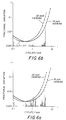
- FIG. 6a and 6b there is illustrated a comparison of translation performance between a carriage assembly having stainless steel roller bearing assemblies and a carriage assembly having plastic bearing assemblies when each carriage assembly was used with stainless steel guide rods.
- Figure 6a illustrates the use of stainless steel bearing assemblies against stainless steel guide rods
- Figure 6b illustrates use of plastic bearing assemblies against stainless steel rods.
- the plots illustrated in Figures 6a and 6b were generated by computing the fourier transform of carriage positional error as measured with a laser interferometer.
- the stainless steel rods and stainless steel bearing assemblies had a modulus of elasticity of about 193GPa (28 x 106 psi).
- the plastic bearing assemblies had an outer sleeve made of a 17% Kevlar filled 6/6 nylon plastic (purchased from A. L. Hyde Co. under the tradename "Hydlar Z”), the filled nylon plastic had a modulus of elasticity of about 6.2GPa (0.9 x 10⁶ psi).
- Hydlar Z a 17% Kevlar filled 6/6 nylon plastic
- the filled nylon plastic had a modulus of elasticity of about 6.2GPa (0.9 x 10⁶ psi).
- the vertical lines in Figure 6a there was a substantial amount of position variation as compared to the use of plastic roller bearing assemblies as applied against the guide rods.
- the stainless steel roller bearings there was substantial amounts of undesirable spectral energy between 0.5 to 4.0 cycle/mm which is not present when the composite plastic sleeves roller bearing assemblies were used as shown in Figure 6b.
- the surface finish (i.e. the roughness) of the contacting surface of the plastic sleeve should be kept to a minimum in order to achieve optimal performance.
- the surface roughness of both the plastic and stainless steel roller bearings is less than about 812nm (32 millionths of an inch).
- the radial runout of the roller gearing assemblies should also be held to a minimum in order to obtain optimal performance.
- the radial runout is less than about 12.7nm (0.0005in).
- the shape and configuration of the surface 83 should be appropriately matched with respect to the guide rod with which it engages. This matching is illustrated by reference to Figure 5.
- the radius R1 of the surface 83 should be equal to or slightly larger than the radius R2 of the outer surface of the guide rods. While R1 and R2 could be identical, it is preferable that R1 be slightly larger in order to compensate for product tolerance variations.
- R1 is in the range of about 101 to 110% of R2. In the embodiment illustrated, R1 is about 103% of R2.
- the plastic sleeves 82 will compress more than the stainless steel, distributing the load over a larger concave area, and thus reducing the contact stress between the guide rod and the plastic sleeve.
- FIG. 7 there is illustrated a modified guide mechanism 110 made in accordance with the present invention.
- the mechanism 110 is similar to guide mechanism 10, like numerals indicating like parts.
- mechanism 110 there is provided only a single roller bearing assembly associated with each of the mounting assemblies 30, 32.
- the mounting assembly 32 still provides the means for allowing compensation of parallel misalignment between the guide rods 14, 16 and for applying a biasing force against guide rod 16 which provides for positive engagement of all the roller bearing assemblies.
- this embodiment has the disadvantage with respect to the previous embodiment in that increased contact force are applied to each of the roller bearing assemblies 120, 122. This becomes important when the weight of the carriage becomes significant.
- roller bearing assemblies are utilized to mount the frame to the guide rods
- other type guide rod engaging elements such as friction pads
- friction pads can be substituted for one or more of the roller bearing assemblies for slideably mounting the frame to the guide rods.
- Use of such friction pads will provide a dampening affect which is beneficial in the incremental motion of the carriage along the guide rods as is described in the preferred embodiment.
- friction pads made of 6/6 nylon material having 17% Kevlar fibers may be used in place on one or more of the roller bearing assemblies.
- an assembly which provides smooth and accurate position of a carriage is provided while also providing long service life.
Landscapes
- Character Spaces And Line Spaces In Printers (AREA)
- Bearings For Parts Moving Linearly (AREA)
- Printers Or Recording Devices Using Electromagnetic And Radiation Means (AREA)
- Transmission Devices (AREA)
Applications Claiming Priority (2)
| Application Number | Priority Date | Filing Date | Title |
|---|---|---|---|
| US08/289,048 US5529412A (en) | 1994-08-11 | 1994-08-11 | Print guide mechanism |
| US289048 | 1994-08-11 |
Publications (3)
| Publication Number | Publication Date |
|---|---|
| EP0696511A2 true EP0696511A2 (de) | 1996-02-14 |
| EP0696511A3 EP0696511A3 (de) | 1998-02-04 |
| EP0696511B1 EP0696511B1 (de) | 2001-11-07 |
Family
ID=23109804
Family Applications (1)
| Application Number | Title | Priority Date | Filing Date |
|---|---|---|---|
| EP95202164A Expired - Lifetime EP0696511B1 (de) | 1994-08-11 | 1995-08-09 | Führungsmechanismus für Drucker |
Country Status (4)
| Country | Link |
|---|---|
| US (1) | US5529412A (de) |
| EP (1) | EP0696511B1 (de) |
| JP (1) | JPH0858174A (de) |
| DE (1) | DE69523685T2 (de) |
Cited By (4)
| Publication number | Priority date | Publication date | Assignee | Title |
|---|---|---|---|---|
| GB2306685A (en) * | 1995-11-01 | 1997-05-07 | Eastman Kodak Co | Printer guide mechanism |
| EP1666268A1 (de) * | 2004-12-03 | 2006-06-07 | Océ-Technologies B.V. | Anordnung zur Führung eines Druckerwagens entlang Führungsmittel |
| EP1693220A4 (de) * | 2003-12-09 | 2007-05-09 | Seiko Epson Corp | Schlitten und aufzeichnungsvorrichtung |
| CN102139587A (zh) * | 2010-01-26 | 2011-08-03 | 精工爱普生株式会社 | 滑架导向机构及打印机 |
Families Citing this family (6)
| Publication number | Priority date | Publication date | Assignee | Title |
|---|---|---|---|---|
| US5755520A (en) * | 1997-04-25 | 1998-05-26 | Eastman Kodak Company | Wear resistant lathe bed scanning apparatus and method |
| US6244122B1 (en) * | 1998-10-01 | 2001-06-12 | University Of North Carolina At Charlotte | Self-aligning decoupled nut mechanism |
| US6471427B1 (en) | 2001-04-06 | 2002-10-29 | Lexmark International, Inc. | Printhead carrier with rotatable bearings |
| JP5960487B2 (ja) * | 2011-06-06 | 2016-08-02 | 株式会社Okiデータ・インフォテック | インクジェットプリンター |
| US10507087B2 (en) | 2016-07-27 | 2019-12-17 | Align Technology, Inc. | Methods and apparatuses for forming a three-dimensional volumetric model of a subject's teeth |
| US12221997B2 (en) * | 2021-03-05 | 2025-02-11 | Illinois Tool Works Inc. | Tubular sleeve |
Citations (2)
| Publication number | Priority date | Publication date | Assignee | Title |
|---|---|---|---|---|
| US5392662A (en) | 1993-09-20 | 1995-02-28 | Eastman Kodak Company | Leadscrew coupler |
| US12383993B2 (en) | 2021-12-09 | 2025-08-12 | Sanhua (Hangzhou) Micro Channel Heat Exchanger Co., Ltd. | Heat exchanger processing method and heat exchanger processing apparatus |
Family Cites Families (19)
| Publication number | Priority date | Publication date | Assignee | Title |
|---|---|---|---|---|
| US3790233A (en) * | 1971-11-10 | 1974-02-05 | Automation Gages Inc | Antifriction slide assembly |
| US3778121A (en) * | 1971-11-18 | 1973-12-11 | Brown & Sharpe Manuf Co | Slide guide having preloaded hollow and solid roller bearings |
| IT986534B (it) * | 1973-06-19 | 1975-01-30 | Olivetti & Co Spa | Dispositivo di scrittura in serie con disco portacaratteri alamine flessibili |
| US4025135A (en) * | 1974-08-14 | 1977-05-24 | Wada Seiko Kabushiki Kaisha (Wada Seiko Co., Ltd.) | Bearing assembly |
| US4111293A (en) * | 1977-01-10 | 1978-09-05 | Xerox Corporation | Ribbon transporting and shifting mechanism |
| DE2738496C3 (de) * | 1977-08-26 | 1980-03-13 | Olympia Werke Ag, 2940 Wilhelmshaven | Schlittenführung für einen Schreibkopfträger an druckenden Büromaschinen |
| US4177471A (en) * | 1977-11-04 | 1979-12-04 | Silonics, Inc. | Carriage and raceway mechanism for an ink jet printer |
| US4317137A (en) * | 1978-05-17 | 1982-02-23 | Harris Corporation | Optical scan head and printer |
| US4445798A (en) * | 1980-02-15 | 1984-05-01 | Nippon Electric Co., Ltd. | Serial printer with a linear motor printer carriage |
| US4493571A (en) * | 1981-10-09 | 1985-01-15 | Iquad Company Incorporated | Print guide mechanism |
| JPS591286A (ja) * | 1982-06-28 | 1984-01-06 | Fujitsu Ltd | 印字ヘツド |
| US4528607A (en) * | 1982-09-30 | 1985-07-09 | Drivetec, Inc. | Magnetic record/playback head positioning apparatus |
| US4566814A (en) * | 1983-04-06 | 1986-01-28 | Standard Precision, Inc. | Print head carriage assembly |
| US4547089A (en) * | 1983-08-19 | 1985-10-15 | At&T Teletype Corporation | Guide for a print head of a printing device |
| JPS6163028A (ja) * | 1984-09-04 | 1986-04-01 | Canon Inc | 移動案内装置 |
| JPS62124973A (ja) * | 1985-11-26 | 1987-06-06 | Seikosha Co Ltd | 印字ヘツドの搬送装置 |
| US4715730A (en) * | 1986-03-26 | 1987-12-29 | Lee Controls, Inc. | Linear motion pillow blocks including self-aligning features |
| DE8807526U1 (de) * | 1988-06-09 | 1989-07-06 | Siemens AG, 1000 Berlin und 8000 München | Registriergerät mit einem quer zur Bewegungsrichtung eines Aufzeichnungsträgers bewegbaren Schreibwagen |
| US4898487A (en) * | 1988-12-08 | 1990-02-06 | Ncr Corporation | Print head carriage for matrix printer |
-
1994
- 1994-08-11 US US08/289,048 patent/US5529412A/en not_active Expired - Lifetime
-
1995
- 1995-08-09 EP EP95202164A patent/EP0696511B1/de not_active Expired - Lifetime
- 1995-08-09 DE DE69523685T patent/DE69523685T2/de not_active Expired - Fee Related
- 1995-08-10 JP JP20426195A patent/JPH0858174A/ja active Pending
Patent Citations (2)
| Publication number | Priority date | Publication date | Assignee | Title |
|---|---|---|---|---|
| US5392662A (en) | 1993-09-20 | 1995-02-28 | Eastman Kodak Company | Leadscrew coupler |
| US12383993B2 (en) | 2021-12-09 | 2025-08-12 | Sanhua (Hangzhou) Micro Channel Heat Exchanger Co., Ltd. | Heat exchanger processing method and heat exchanger processing apparatus |
Cited By (6)
| Publication number | Priority date | Publication date | Assignee | Title |
|---|---|---|---|---|
| GB2306685A (en) * | 1995-11-01 | 1997-05-07 | Eastman Kodak Co | Printer guide mechanism |
| EP1693220A4 (de) * | 2003-12-09 | 2007-05-09 | Seiko Epson Corp | Schlitten und aufzeichnungsvorrichtung |
| US7390077B2 (en) | 2003-12-09 | 2008-06-24 | Seiko Epson Corporation | Carriage and recording apparatus incorporating the same |
| EP1666268A1 (de) * | 2004-12-03 | 2006-06-07 | Océ-Technologies B.V. | Anordnung zur Führung eines Druckerwagens entlang Führungsmittel |
| CN102139587A (zh) * | 2010-01-26 | 2011-08-03 | 精工爱普生株式会社 | 滑架导向机构及打印机 |
| CN102139587B (zh) * | 2010-01-26 | 2014-06-04 | 精工爱普生株式会社 | 滑架导向机构及打印机 |
Also Published As
| Publication number | Publication date |
|---|---|
| DE69523685T2 (de) | 2002-08-01 |
| EP0696511B1 (de) | 2001-11-07 |
| US5529412A (en) | 1996-06-25 |
| DE69523685D1 (de) | 2001-12-13 |
| EP0696511A3 (de) | 1998-02-04 |
| JPH0858174A (ja) | 1996-03-05 |
Similar Documents
| Publication | Publication Date | Title |
|---|---|---|
| EP0696511B1 (de) | Führungsmechanismus für Drucker | |
| KR100584533B1 (ko) | 인쇄기용 감광벨트 조정장치 | |
| US4421228A (en) | Periodically aligning an endless web | |
| US5214448A (en) | Belt-drive tensioning system which uses a pivoting member | |
| EP0458260B1 (de) | Bandantriebssystem | |
| GB2306685A (en) | Printer guide mechanism | |
| US5333513A (en) | Averaging half-nuts | |
| US4996559A (en) | Optical system supporting mechanism for an image processing equipment | |
| US5280309A (en) | Single degree of freedom belt drive tensioning system for a plotter apparatus | |
| US5445460A (en) | Pressure-contact device for applying print head onto platen of printer | |
| CA2183521C (en) | Lens mounting | |
| JP2868879B2 (ja) | ベルト駆動装置 | |
| FI102206B (fi) | Siirtolaite | |
| US6422100B1 (en) | Independently-tensioned multiple-cable translation system | |
| JPH1115269A (ja) | 画像形成装置 | |
| US5333005A (en) | Apparatus for raising and lowering plotter marking devices | |
| EP0570180B1 (de) | Verfahren und Gerät für Interfacekodiereinrichtung mit Drehsicherung | |
| US4922247A (en) | Encoder mount | |
| US6334565B1 (en) | Conveying a recording medium | |
| JPH109359A (ja) | テーブル送り機構 | |
| JP2539249B2 (ja) | 露光用ヘッドの支持機構 | |
| JP2825635B2 (ja) | ベルト駆動装置 | |
| JPH02104164A (ja) | 画像読取装置 | |
| JP3466325B2 (ja) | キャリッジ移動機構 | |
| JPH11254775A (ja) | シリアル型記録装置 |
Legal Events
| Date | Code | Title | Description |
|---|---|---|---|
| PUAI | Public reference made under article 153(3) epc to a published international application that has entered the european phase |
Free format text: ORIGINAL CODE: 0009012 |
|
| AK | Designated contracting states |
Kind code of ref document: A2 Designated state(s): DE FR GB |
|
| PUAL | Search report despatched |
Free format text: ORIGINAL CODE: 0009013 |
|
| AK | Designated contracting states |
Kind code of ref document: A3 Designated state(s): CH DE FR GB IT LI |
|
| 17P | Request for examination filed |
Effective date: 19980713 |
|
| 17Q | First examination report despatched |
Effective date: 19990819 |
|
| GRAG | Despatch of communication of intention to grant |
Free format text: ORIGINAL CODE: EPIDOS AGRA |
|
| GRAG | Despatch of communication of intention to grant |
Free format text: ORIGINAL CODE: EPIDOS AGRA |
|
| GRAH | Despatch of communication of intention to grant a patent |
Free format text: ORIGINAL CODE: EPIDOS IGRA |
|
| RBV | Designated contracting states (corrected) |
Designated state(s): DE FR GB |
|
| GRAH | Despatch of communication of intention to grant a patent |
Free format text: ORIGINAL CODE: EPIDOS IGRA |
|
| GRAA | (expected) grant |
Free format text: ORIGINAL CODE: 0009210 |
|
| AK | Designated contracting states |
Kind code of ref document: B1 Designated state(s): DE FR GB |
|
| REF | Corresponds to: |
Ref document number: 69523685 Country of ref document: DE Date of ref document: 20011213 |
|
| REG | Reference to a national code |
Ref country code: GB Ref legal event code: IF02 |
|
| ET | Fr: translation filed | ||
| PLBE | No opposition filed within time limit |
Free format text: ORIGINAL CODE: 0009261 |
|
| STAA | Information on the status of an ep patent application or granted ep patent |
Free format text: STATUS: NO OPPOSITION FILED WITHIN TIME LIMIT |
|
| 26N | No opposition filed | ||
| PGFP | Annual fee paid to national office [announced via postgrant information from national office to epo] |
Ref country code: GB Payment date: 20030702 Year of fee payment: 9 |
|
| PGFP | Annual fee paid to national office [announced via postgrant information from national office to epo] |
Ref country code: FR Payment date: 20030804 Year of fee payment: 9 |
|
| PGFP | Annual fee paid to national office [announced via postgrant information from national office to epo] |
Ref country code: DE Payment date: 20030829 Year of fee payment: 9 |
|
| PG25 | Lapsed in a contracting state [announced via postgrant information from national office to epo] |
Ref country code: GB Free format text: LAPSE BECAUSE OF NON-PAYMENT OF DUE FEES Effective date: 20040809 |
|
| PG25 | Lapsed in a contracting state [announced via postgrant information from national office to epo] |
Ref country code: DE Free format text: LAPSE BECAUSE OF NON-PAYMENT OF DUE FEES Effective date: 20050301 |
|
| GBPC | Gb: european patent ceased through non-payment of renewal fee |
Effective date: 20040809 |
|
| PG25 | Lapsed in a contracting state [announced via postgrant information from national office to epo] |
Ref country code: FR Free format text: LAPSE BECAUSE OF NON-PAYMENT OF DUE FEES Effective date: 20050429 |
|
| REG | Reference to a national code |
Ref country code: FR Ref legal event code: ST |