EP0699848B1 - Automatische Spannvorrichtung für endlose, flexible Antriebsmittel - Google Patents
Automatische Spannvorrichtung für endlose, flexible Antriebsmittel Download PDFInfo
- Publication number
- EP0699848B1 EP0699848B1 EP95113640A EP95113640A EP0699848B1 EP 0699848 B1 EP0699848 B1 EP 0699848B1 EP 95113640 A EP95113640 A EP 95113640A EP 95113640 A EP95113640 A EP 95113640A EP 0699848 B1 EP0699848 B1 EP 0699848B1
- Authority
- EP
- European Patent Office
- Prior art keywords
- swinging member
- fixed
- shaft
- swinging
- timing belt
- Prior art date
- Legal status (The legal status is an assumption and is not a legal conclusion. Google has not performed a legal analysis and makes no representation as to the accuracy of the status listed.)
- Expired - Lifetime
Links
- 238000006073 displacement reaction Methods 0.000 claims description 47
- 230000002093 peripheral effect Effects 0.000 claims description 37
- 230000010355 oscillation Effects 0.000 claims description 29
- 239000007788 liquid Substances 0.000 claims description 16
- 230000008602 contraction Effects 0.000 claims description 7
- 230000001627 detrimental effect Effects 0.000 claims description 6
- 230000004323 axial length Effects 0.000 claims description 5
- 230000001133 acceleration Effects 0.000 claims description 3
- 238000010276 construction Methods 0.000 description 52
- 238000013016 damping Methods 0.000 description 17
- 238000012360 testing method Methods 0.000 description 15
- 230000006835 compression Effects 0.000 description 12
- 238000007906 compression Methods 0.000 description 12
- 238000002474 experimental method Methods 0.000 description 12
- 238000005259 measurement Methods 0.000 description 10
- 238000003825 pressing Methods 0.000 description 7
- 238000004519 manufacturing process Methods 0.000 description 6
- 230000008859 change Effects 0.000 description 5
- 238000009434 installation Methods 0.000 description 5
- 238000000034 method Methods 0.000 description 5
- 238000005096 rolling process Methods 0.000 description 5
- 238000013461 design Methods 0.000 description 4
- 230000001276 controlling effect Effects 0.000 description 3
- 230000000694 effects Effects 0.000 description 3
- 238000011835 investigation Methods 0.000 description 3
- 230000002265 prevention Effects 0.000 description 3
- 230000009467 reduction Effects 0.000 description 3
- XEEYBQQBJWHFJM-UHFFFAOYSA-N Iron Chemical compound [Fe] XEEYBQQBJWHFJM-UHFFFAOYSA-N 0.000 description 2
- 230000009471 action Effects 0.000 description 2
- 238000004891 communication Methods 0.000 description 2
- 230000000052 comparative effect Effects 0.000 description 2
- 238000010586 diagram Methods 0.000 description 2
- 229910000838 Al alloy Inorganic materials 0.000 description 1
- RYGMFSIKBFXOCR-UHFFFAOYSA-N Copper Chemical compound [Cu] RYGMFSIKBFXOCR-UHFFFAOYSA-N 0.000 description 1
- 229910000639 Spring steel Inorganic materials 0.000 description 1
- 229910000831 Steel Inorganic materials 0.000 description 1
- 230000002159 abnormal effect Effects 0.000 description 1
- 238000013459 approach Methods 0.000 description 1
- 238000005452 bending Methods 0.000 description 1
- 229910052802 copper Inorganic materials 0.000 description 1
- 239000010949 copper Substances 0.000 description 1
- 230000003111 delayed effect Effects 0.000 description 1
- 230000001419 dependent effect Effects 0.000 description 1
- 230000005484 gravity Effects 0.000 description 1
- 230000006872 improvement Effects 0.000 description 1
- 229910052742 iron Inorganic materials 0.000 description 1
- 238000003754 machining Methods 0.000 description 1
- 238000011089 mechanical engineering Methods 0.000 description 1
- 229910052751 metal Inorganic materials 0.000 description 1
- 239000002184 metal Substances 0.000 description 1
- 230000001105 regulatory effect Effects 0.000 description 1
- 238000011160 research Methods 0.000 description 1
- 230000000717 retained effect Effects 0.000 description 1
- 230000010360 secondary oscillation Effects 0.000 description 1
- 239000010935 stainless steel Substances 0.000 description 1
- 229910001220 stainless steel Inorganic materials 0.000 description 1
- 239000010959 steel Substances 0.000 description 1
- 230000001360 synchronised effect Effects 0.000 description 1
- XLYOFNOQVPJJNP-UHFFFAOYSA-N water Substances O XLYOFNOQVPJJNP-UHFFFAOYSA-N 0.000 description 1
Images


Classifications
-
- F—MECHANICAL ENGINEERING; LIGHTING; HEATING; WEAPONS; BLASTING
- F16—ENGINEERING ELEMENTS AND UNITS; GENERAL MEASURES FOR PRODUCING AND MAINTAINING EFFECTIVE FUNCTIONING OF MACHINES OR INSTALLATIONS; THERMAL INSULATION IN GENERAL
- F16H—GEARING
- F16H7/00—Gearings for conveying rotary motion by endless flexible members
- F16H7/08—Means for varying tension of belts, ropes or chains
-
- F—MECHANICAL ENGINEERING; LIGHTING; HEATING; WEAPONS; BLASTING
- F16—ENGINEERING ELEMENTS AND UNITS; GENERAL MEASURES FOR PRODUCING AND MAINTAINING EFFECTIVE FUNCTIONING OF MACHINES OR INSTALLATIONS; THERMAL INSULATION IN GENERAL
- F16F—SPRINGS; SHOCK-ABSORBERS; MEANS FOR DAMPING VIBRATION
- F16F9/00—Springs, vibration-dampers, shock-absorbers, or similarly-constructed movement-dampers using a fluid or the equivalent as damping medium
- F16F9/32—Details
- F16F9/3207—Constructional features
-
- F—MECHANICAL ENGINEERING; LIGHTING; HEATING; WEAPONS; BLASTING
- F16—ENGINEERING ELEMENTS AND UNITS; GENERAL MEASURES FOR PRODUCING AND MAINTAINING EFFECTIVE FUNCTIONING OF MACHINES OR INSTALLATIONS; THERMAL INSULATION IN GENERAL
- F16H—GEARING
- F16H7/00—Gearings for conveying rotary motion by endless flexible members
- F16H7/08—Means for varying tension of belts, ropes or chains
- F16H7/0848—Means for varying tension of belts, ropes or chains with means for impeding reverse motion
-
- F—MECHANICAL ENGINEERING; LIGHTING; HEATING; WEAPONS; BLASTING
- F16—ENGINEERING ELEMENTS AND UNITS; GENERAL MEASURES FOR PRODUCING AND MAINTAINING EFFECTIVE FUNCTIONING OF MACHINES OR INSTALLATIONS; THERMAL INSULATION IN GENERAL
- F16H—GEARING
- F16H7/00—Gearings for conveying rotary motion by endless flexible members
- F16H7/08—Means for varying tension of belts, ropes or chains
- F16H7/10—Means for varying tension of belts, ropes or chains by adjusting the axis of a pulley
- F16H7/12—Means for varying tension of belts, ropes or chains by adjusting the axis of a pulley of an idle pulley
- F16H7/1209—Means for varying tension of belts, ropes or chains by adjusting the axis of a pulley of an idle pulley with vibration damping means
- F16H7/1236—Means for varying tension of belts, ropes or chains by adjusting the axis of a pulley of an idle pulley with vibration damping means of the fluid and restriction type, e.g. dashpot
-
- F—MECHANICAL ENGINEERING; LIGHTING; HEATING; WEAPONS; BLASTING
- F02—COMBUSTION ENGINES; HOT-GAS OR COMBUSTION-PRODUCT ENGINE PLANTS
- F02B—INTERNAL-COMBUSTION PISTON ENGINES; COMBUSTION ENGINES IN GENERAL
- F02B2275/00—Other engines, components or details, not provided for in other groups of this subclass
- F02B2275/18—DOHC [Double overhead camshaft]
-
- F—MECHANICAL ENGINEERING; LIGHTING; HEATING; WEAPONS; BLASTING
- F02—COMBUSTION ENGINES; HOT-GAS OR COMBUSTION-PRODUCT ENGINE PLANTS
- F02B—INTERNAL-COMBUSTION PISTON ENGINES; COMBUSTION ENGINES IN GENERAL
- F02B67/00—Engines characterised by the arrangement of auxiliary apparatus not being otherwise provided for, e.g. the apparatus having different functions; Driving auxiliary apparatus from engines, not otherwise provided for
- F02B67/04—Engines characterised by the arrangement of auxiliary apparatus not being otherwise provided for, e.g. the apparatus having different functions; Driving auxiliary apparatus from engines, not otherwise provided for of mechanically-driven auxiliary apparatus
- F02B67/06—Engines characterised by the arrangement of auxiliary apparatus not being otherwise provided for, e.g. the apparatus having different functions; Driving auxiliary apparatus from engines, not otherwise provided for of mechanically-driven auxiliary apparatus driven by means of chains, belts, or like endless members
-
- F—MECHANICAL ENGINEERING; LIGHTING; HEATING; WEAPONS; BLASTING
- F16—ENGINEERING ELEMENTS AND UNITS; GENERAL MEASURES FOR PRODUCING AND MAINTAINING EFFECTIVE FUNCTIONING OF MACHINES OR INSTALLATIONS; THERMAL INSULATION IN GENERAL
- F16H—GEARING
- F16H7/00—Gearings for conveying rotary motion by endless flexible members
- F16H7/08—Means for varying tension of belts, ropes or chains
- F16H2007/0802—Actuators for final output members
- F16H2007/0806—Compression coil springs
-
- F—MECHANICAL ENGINEERING; LIGHTING; HEATING; WEAPONS; BLASTING
- F16—ENGINEERING ELEMENTS AND UNITS; GENERAL MEASURES FOR PRODUCING AND MAINTAINING EFFECTIVE FUNCTIONING OF MACHINES OR INSTALLATIONS; THERMAL INSULATION IN GENERAL
- F16H—GEARING
- F16H7/00—Gearings for conveying rotary motion by endless flexible members
- F16H7/08—Means for varying tension of belts, ropes or chains
- F16H2007/0802—Actuators for final output members
- F16H2007/081—Torsion springs
-
- F—MECHANICAL ENGINEERING; LIGHTING; HEATING; WEAPONS; BLASTING
- F16—ENGINEERING ELEMENTS AND UNITS; GENERAL MEASURES FOR PRODUCING AND MAINTAINING EFFECTIVE FUNCTIONING OF MACHINES OR INSTALLATIONS; THERMAL INSULATION IN GENERAL
- F16H—GEARING
- F16H7/00—Gearings for conveying rotary motion by endless flexible members
- F16H7/08—Means for varying tension of belts, ropes or chains
- F16H2007/0802—Actuators for final output members
- F16H2007/0812—Fluid pressure
-
- F—MECHANICAL ENGINEERING; LIGHTING; HEATING; WEAPONS; BLASTING
- F16—ENGINEERING ELEMENTS AND UNITS; GENERAL MEASURES FOR PRODUCING AND MAINTAINING EFFECTIVE FUNCTIONING OF MACHINES OR INSTALLATIONS; THERMAL INSULATION IN GENERAL
- F16H—GEARING
- F16H7/00—Gearings for conveying rotary motion by endless flexible members
- F16H7/08—Means for varying tension of belts, ropes or chains
- F16H7/0848—Means for varying tension of belts, ropes or chains with means for impeding reverse motion
- F16H2007/0859—Check valves
-
- F—MECHANICAL ENGINEERING; LIGHTING; HEATING; WEAPONS; BLASTING
- F16—ENGINEERING ELEMENTS AND UNITS; GENERAL MEASURES FOR PRODUCING AND MAINTAINING EFFECTIVE FUNCTIONING OF MACHINES OR INSTALLATIONS; THERMAL INSULATION IN GENERAL
- F16H—GEARING
- F16H7/00—Gearings for conveying rotary motion by endless flexible members
- F16H7/08—Means for varying tension of belts, ropes or chains
- F16H2007/0876—Control or adjustment of actuators
- F16H2007/0878—Disabling during transport
-
- F—MECHANICAL ENGINEERING; LIGHTING; HEATING; WEAPONS; BLASTING
- F16—ENGINEERING ELEMENTS AND UNITS; GENERAL MEASURES FOR PRODUCING AND MAINTAINING EFFECTIVE FUNCTIONING OF MACHINES OR INSTALLATIONS; THERMAL INSULATION IN GENERAL
- F16H—GEARING
- F16H7/00—Gearings for conveying rotary motion by endless flexible members
- F16H7/08—Means for varying tension of belts, ropes or chains
- F16H2007/0889—Path of movement of the finally actuated member
- F16H2007/0891—Linear path
Definitions
- the present invention relates to an autotensioner used for applying an appropriate tension to a timing belt of an automotive engine.
- the timing belt has an inner peripheral face formed with teeth, so that these teeth are engaged with the teeth formed on the outer peripheral face of the drive and follower pulleys.
- timing belt With this type of timing belt, it is necessary to apply an appropriate tension to prevent so-called "tooth jump" with creep of the teeth on the inner peripheral face of the timing belt relative to the teeth on the outer peripheral face of the drive pulley and follower pulley due to e.g. temperature changes.
- An autotensioner used for this purpose must achieve the following functions (1) and (2):
- An autotensioner is therefore provided with a spring to ensure the above function (1), and a damper unit to ensure function (2).
- the damper unit there is the so-called one way configured unit such as disclosed in Japanese Patent First Publication KOKAI No. S63-180759, having a damper function in both directions.
- a so-called two way configured unit with a damping function in one direction only, so that the pulley pressing against the timing belt can be rapidly displaced in the direction of pressure and gradually displaced in the opposite direction.
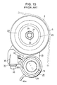
- Japanese Utility Model First Publication KOKAI No. 60-23355 discloses a construction as shown in Figs.1 and 2, for an autotensioner incorporating such a two way configured damper unit.
- Fig.1 shows a timing belt drive unit with an autotensioner 4 fitted in it. Rotation of an engine crank shaft is transmitted from a drive pulley 1 to a timing belt 2, to thereby rotate follower pulleys 3 and cam shafts (not shown in the figure) fixed to respective ends of the follower pulleys 3.
- a follower pulley 3a is provided for driving auxiliary machinery of a water pump and the like.
- the autotensioner 4 has a pulley 5 which is resiliently pressed against a portion of the timing belt 2 at a central part between the drive pulley 1 and the follower pulley 3, to thereby apply an appropriate tension to the timing belt 2.
- the pulley 5 is pivotally supported by a second shaft (not shown in the figure) at a central portion of a swinging member 6.
- the swinging member 6 is also referred to as pivotal member or rocking member.
- the swinging member 6 is pivotally supported on a fixed portion or front face of the engine cylinder block (not shown) by means of a first shaft or pivot shaft 7.
- a damper unit 9 as shown in detail in Fig.2, is provided between a bearing portion 8 on a tip end of the swinging member 6, and the front face of the cylinder block (not shown).
- the damper unit 9 is fixed, for example to the front face of the cylinder block (not shown), at a portion separate from the swinging member 6, and exerts a resilient force in a direction of extension in overall length, based on the resilient force of a compression spring 11 housed in a cylinder 10, so that the pulley 5 is resiliently pressed towards the timing belt 2, under the resilient force of the compression spring 11.
- the damper unit 9 extends rapidly but contracts gradually. Accordingly, the autotensioner 4 satisfies the beforementioned functions (1), (2).
- the damper unit 9 is relatively large. That is to say, in order to apply a sufficient tension to the timing belt 2, the resilient force of the compression spring 11 must be large, and since in general this resilient force must be maintained at around 10 to 20 kgf, it is difficult to avoid having a large compression spring 11 (in length and diameter).
- the damper unit 9 in which the compression spring 11 is housed thus becomes large (in length and diameter), so that it becomes difficult to install an autotensioner 4 incorporating such a large damper unit 9 in a limited installation space, for example at the front face of the cylinder block.
- the damper unit 9 of the conventional construction shown in Figs.1 and 2 also lacks universal application, requiring a large variety of damper units 9 to suit autotensioners for different kinds of engines, resulting in an increase in manufacturing costs of the autotensioner 4, due to the complexity of component manufacture and component management. That is to say, not only does the set value for the tension of the timing belt 2 change with engine displacement, but also there are subtle differences, due for example to the engine type (whether OHC or DOHC). Accordingly, it is necessary to change the resilient force of the compression spring 11 to suit the set value. However, when the resilient force is changed, the length and diameter of the compression spring 11 become different. Therefore, the size of the damper unit 9 in which the compression spring 11 is housed is variously changed depending on the different set values, causing an increase in the abovementioned manufacturing costs.
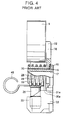
- Japanese Utility Model First Publication KOKAI No. H6-47757 discloses an autotensioner such as shown in Figs.3 to 5 having a construction wherein a common damper unit is possible for configurations having different set values for the tension, and also the damper unit can be of small size.
- a damper unit such as shown in Fig. 6, is fitted to this conventional autotensioner.
- the damper unit shown in Fig.6 is a specific device based on the damper unit disclosed in the above publication KOKAI No. H6-47757. Since the autotensioner shown in Figs.3 to 5 and the damper unit shown in Fig.6 are substantially the same in basic construction to the autotensioner and damper unit used in the tests during the stages to completion of the present invention, these will be briefly described in detail.
- a fixed or stationary member 14 is fixed to a fixed portion, for example on the front face of the cylinder block, by means of a bolt (not shown) inserted into an attachment hole 15 in a central portion of the fixed member 14.
- a first shaft or fixed shaft 17 is inserted into an aperture 16 formed in an end portion (upper end portion in Figs.3 to 5) of the fixed member 14.
- a base end of the fixed shaft 17 is internally fixed to the aperture 16.
- a swinging member 18 is pivotally supported by the fixed member 14. Specifically, a base end (lower end portion in Figs.3 to 5) of the swinging member 18 is supported so as to turn freely about the fixed shaft 17 by externally fitting a cylindrical portion 19 formed on the base end of the swinging member 18, around the fixed shaft 17 by way of a plain bearing 20. Furthermore, a bolt 21 passing through the fixed shaft 17 is screwed into a threaded hole formed in a fixed portion, such as on the front face of the cylinder block, thereby co-operating with the bolt (not shown) inserted into the attachment aperture 15, to prevent turning of the fixed member 14.
- a pulley 5 is rotatably supported around the protrusion 22 by a rolling bearing 23. More specifically, a bolt 24 is passed through a central aperture of an inner ring 25 of the rolling bearing 23, and through a washer 26 and then tightened with a nut 27, to thus retain the peripheral portion around the central aperture of the inner ring 25.
- the fixed shaft 17 is located radially outwards from the outer peripheral face of the pulley 5.
- the first axis along which the fixed shaft is located is spaced apart from the second axis along which the pulley 5 is located, by a length longer than the radius of the pulley 5.
- a coil portion 29 of a torsion coil spring 28 is located around the cylindrical portion 19 of the swinging member 18.
- One engaging portion 30a of the torsion coil spring 28 is engaged in a engaging aperture 31a formed in the fixed member 14, while another engaging portion 30b is inserted via a sleeve 32, into an engaging aperture 31b formed in the swinging member 18. Due to the torsion coil spring 28, a resilient force is applied to the swinging member 18 so as to turn it in a clockwise direction in Fig.3, about the fixed shaft 17.
- a damper unit 34 has a base end which is supported on a fixed arm or projection 33 provided on a part of the fixed member 14 at a location away from the fixed shaft 17.
- the swinging member has a swinging arm 35 which is provided on a part of the swinging member 18 at a location away from the protrusion 22, so that a bearing or receiving block 37 is internally fixed in a cavity 36 formed in the swinging arm 35.
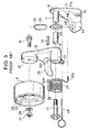
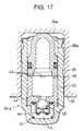
- the damper unit 34 as shown in Fig. 6, has a cylinder 39 within which a viscous liquid 12 is contained, a plunger 38 which has a tip end abutted against an end face of the bearing block 37 and a piston 40 which is fitted inside the cylinder 39 so as to be freely movable in the axial direction (up / down direction in Fig. 6).
- a biasing spring or compression coil spring 41 is provided between the piston 40 and an internal end face of the cylinder 39 (lower end face in Fig.6) so as to press the piston 40 in a direction out of the cylinder 39.
- the plunger 38 has a base end face thereof (lower end face in Fig.6) abutted against the piston 40. Accordingly, when the piston 40 is displaced (pushed upwards) due to the resilient force of the biasing spring 41, the amount of protrusion of the plunger 38 from the cylinder 39 increases.
- An oil passage 42 is formed in a central portion of the piston 40, thus providing communication between both axial end faces of the piston 40.
- a lower end opening of the oil passage 42 is opened or closed by a ball 43 which is pressed against the opening under the resilient force of a compression spring 44, thus making up a ball valve type check valve 45.
- the check valve 45 closes when the piston 40 is displaced (lowered) against the resilient force of the biasing spring 41, and opens when the piston 40 is raised due to the resilient force of the biasing spring 41.
- a stopper pin 46 is provided to immobilize swinging of the swinging member 18 about the fixed shaft 17 irrespective of the resilient force of the torsion coil spring 28, to thus facilitate the fitting of the timing belt 2 around the pulley 5.
- the swinging member 18 is swung or pivoted against the resilient force of the torsion coil spring 28, to align a small hole 47 formed in the swinging member 18 and a small hole 48 formed in the fixed member 14, and the stopper pin 46 is then inserted through both holes 47, 48.
- the timing belt 2 can be easily fitted around the pulley 5, since the pulley 5 which is supported on the swinging member 18, is not displaced by the resilient force of the torsion coil spring 28. After fitting the timing belt 2, the stopper pin 46 is removed, so that the pulley 5 presses against the timing belt 2 under the resilient force of the torsion coil spring 28.
- the swinging member 18 is swung or pivoted by the resilient force of the coil spring 28, so that the pulley 5, rotatably mounted on the tip end portion of the swinging member 18, is resiliently pressed against the timing belt 2, thus restricting the movement of the swinging member 18, so that there is no further displacement of the swinging arm 35 located on the swinging member 18.
- the piston 40 of the damper unit 34 is displaced due to the resilient force of the biasing spring 41, so that the amount of protrusion of the plunger 38 from the cylinder 39 increases, the tip end of the plunger 38 is pressed against the bearing block 37 supported on the tip end portion of the swinging arm 35.
- the swinging member 18 is swung or pivoted in a clockwise direction in Fig.3 about the fixed shaft 17 under the resilient force of the coil spring 28, so that the pulley 5 follows the movement of the timing belt 2.
- the displacement of the plunger 38 is slightly delayed, so that the tip end of the plunger 38 separates from the bearing block 37.
- the swinging member 18 which is swung or pivoted in order that the pulley 5 follows the movement of the timing belt 2, receives absolutely no resistance from the damper unit 34.
- the pulley 5 can thus quickly follow the movement of the timing belt 2, thereby avoiding a drop in tension in the timing belt 2.
- the plunger 38 moves out of the cylinder 39 under the resilient force of the biasing spring 41, slightly slower than the movement of the swinging member 18, until the tip end thereof bumps against the bearing block 37.
- the check valve 45 inside the damper unit 34 opens, so that the piston 40 and plunger 38 are displaced comparatively quickly. There is thus only a very short time delay before the tip end of the plunger 38 bumps against the bearing block 37.
- the displacement of the pulley 5 supported on the swinging member 18 can also only proceed slowly under the operation of the damper unit 34, so that the timing belt 2 is controlled by the pulley 5, and growth of oscillations in the timing belt 2 is suppressed.
- the resilient force for pressing the pulley 5 against the timing belt 2 is obtained by the torsion coil spring 28 which is used for that purpose only. Therefore since the biasing spring 41 housed in the damper unit 34 only has the role of extending the damper unit 34, a large resilient force is not required, so that the damper unit 34 can be small. Moreover, since the same type of damper unit 34 can be used for a variety of types of autotensioner having different tension settings, manufacturing costs can be reduced due to simplification of component manufacture and component management.
- the timing belt 2 is oscillated due to the vibrations transmitted from the engine, and also due to for example fluctuations (size and speed) in the drive force transmitted from the crankshaft, so that the timing belt 2 experiences small changes in tension. That is to say, during engine operation, the tension in the timing belt 2 changes sinusoidally with a frequency proportional to the engine rotational speed.
- the autotensioner comprises; a first shaft supported on a fixed portion directly or by way of a fixed member fixed to the fixed portion, a swinging member freely swinging about the first shaft, a second shaft parallel to the first shaft provided on one part of the swinging member separated from the first shaft, a pulley supported so as to be freely rotatable about the second shaft, a tensioning spring provided between the fixed portion or the fixed member and the swinging member, for applying a resilient force to the swinging member to press the pulley towards a timing belt, and a damper unit provided between the fixed portion or fixed member and the swinging member, for providing a resistance to displacement of the swinging member, against the resilient force of the tensioning spring.
- the damper unit comprises; a cylinder in which viscous liquid is sealed, a piston fitted inside the cylinder so as to be movable in an axial direction thereof, a biasing spring provided between the piston and the cylinder for biasing the piston in one direction, a plunger which protrudes increasingly from the cylinder with displacement of the piston under a resilient force of the biasing spring, an oil passage communicating between both axial end faces of the piston, and a check valve provided in series with the oil passage and adapted to open only when the piston is displaced under the resilient force of the biasing spring. Furthermore, the tensioning spring is provided outside of the cylinder.
- the temperature of the autotensioner during engine operation, and also with the seasons, can rise to in the range of about 80 to about 120 degrees Celsius. Accordingly for values such as the kinetic viscosity ( ⁇ ) and density ( ⁇ ) of the viscous liquid, where the influence of temperature change cannot be disregarded, values for the operating condition temperatures (for example 100 degrees Celsius) are used. In practice, dimensional changes accompanying thermal expansion can be disregarded. If this is not possible, the relevant dimensions are made those for the respective operating conditions.
- leak gap width (h 1 ) is for the half amplitude (y/2) of 0.7mm, while the leak gap width (h 2 ) is for the half amplitude (y/2) of 0.05mm.
- the resilient force for pressing the pulley against the timing belt comes from a tensioning spring provided outside of the damper unit. Consequently, the resilient force of the biasing spring housed inside the damper unit need only be sufficient for extending the damper unit.
- the biasing spring can thus be small enabling a reduction in size of the damper unit so that the autotensioner can be installed in a limited space.
- the pulley displacement width (y) accompanying the oscillation of the timing belt can be controlled within a range from 0.1 to 1.4 mm.
- the vibrations of the timing belt controlled by the pulley can be kept small. As a result, the generation of abnormal vibrations in parts driven by the timing belt, and the occurrence of tooth jump, can be effectively prevented.
- the displacement width (y) is kept equal to or above 0.1mm, then when the tension in the timing belt rises rapidly so that the pulley is pressed hard, the energy to cause the rapid rise in tension of the timing belt can be absorbed by a certain amount. As a result, the life of the timing belt can be sufficiently maintained.
- the displacement width (y) can be maintained equal to or above 0.1mm by having the width (h) of the leak gap above (h 2 ), that is (h ⁇ h 2 ), the life of the timing belt can be maintained.
- the width (h) of the leak gap is kept equal to or above 0.002mm (2 microns), then the operation of inserting the piston into the cylinder in assembling the damper unit, can be adequately carried out at the factory level.
- the damper unit assembly operation becomes difficult. That is to say, with the damper unit fitted to the autotensioner according to the present invention, it is necessary to control the width (h) of the leak gap to a desirable value.
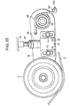
- a timing belt 2a fitted around pulleys 50a, 50b was tensioned by a spring 51.
- a predetermined resilient force was applied to the pulley 50a by means of a spring 52 acting through a swinging member 53, to apply a predetermined tension to the belt 2a.
- the tension of the belt 2a was varied sinusoidally by means of an exciter 54, and the fluctuations in tension were measured by a load cell 55, and simultaneously the displacements of the pulley 50a were measured by a non-contact type displacement sensor 56.
- the present inventor was able to investigate the influence of miniaturization of the damper unit 34 on the displacement characteristics of the pulley 50a of the autotensioner, and on flutter of the timing belt 2a.
- the present inventor variously changed the width (h) of the leak gap and the outer diameter (d) of the piston, and carried out experiments using the test apparatus of Fig.7 to measure displacements of the pulley 5. It was found that the width (h) of the leak gap, in particular the upper limit value for the width (h), to obtain a sufficient damper performance differed depending on the outer diameter (d).
- test conditions for measuring the displacement, apart from those for the outer diameter (d) and the leak gap width (h), are as follows:
- the kinematic viscosity of the viscous liquid 12 was made to conform to the kinematic viscosity of oil generally used as the viscous liquid in autotensioner damper units, at 100 degrees Celsius which is a general autotensioner operating conditions temperature.
- the axial length (L) is approximately equal to the length of the piston 40.
- the width (h) expressed by (r - d) / 2 being half the difference between the inner diameter (r) of the cylinder 39 and the outer diameter (d) of the piston was changed to examine the influence of the width (h) to the performance of the damper unit 34.
- the performance of the damper unit 34 was measured by the displacement width (y) of the pulley 5 accompanying the tension fluctuations in the timing belt 2.
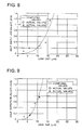
- the half amplitude (y/2) being half of the displacement width (y), is shown together with the leak gap width (h) in the following Table 1 and in Fig.8.
- (X p-p ) is used in lieu of (y).
- the symbols O and X indicate the experimental values for the half amplitude (y/2).
- the symbol 0 represents the range wherein sufficient oscillation prevention effect can be obtained (half amplitude of 0.7mm or less), that is to say, in the example of the present invention, while the symbol X represents the range wherein oscillation prevention effect is inadequate (half amplitude exceeds 0.7mm), that is to say in a comparative example outside of the technical range of the present invention.
- the half amplitude (y/2) of the pulley 5 was measured with the outer diameter (d) of the piston 40 at 8.0mm, and the other conditions the same as for the first measurement experiment. The results are shown together with the width (h) of the leak gap in the following Table 2 and in Fig.9. In Fig.9, (X p-p ) is used in lieu of (y). Leak gap (microns) 3 6 9 11 Half amplitude (mm) 0.11 0.14 0.55 0.76
- the half amplitude (y/2) of the pulley 5 was measured with the diameter (d) of the piston 40 at 13.0mm, and the other conditions the same as for the first and second measurement experiments. The results are shown together with the width (h) of the leak gap in the following Table 3 and in Fig.10. In FIg.10, (X p-p ) is used in lieu of (y). Leak gap (microns) 3 6 11 14 18 Half amplitude (mm) 0.02 0.13 0.22 0.36 1.03
- the width (h) of the leak gap in particular the upper limit value for the width (h) differs depending on the outer diameter (d) of the piston 40 to obtain a sufficient damper performance. Accordingly, it is necessary to realize a technique to obtain sufficient performance also for different sizes of the damper unit 34. In consideration of this situation, the present inventor completed the present invention by the following course of experiments.
- the range of 0.1 to 1.4mm was set as allowable for the displacement width (y) of the timing belt 2. That is to say, the half amplitude (y/2) was made 0.05 to 0.7mm (0.05mm ⁇ (y/2) ⁇ 0.7mm).
- the lower limit was controlled to avoid unreasonable stress on the teeth on the inner peripheral face of the timing belt 2. More specifically, when the tension of the timing belt 2 rises rapidly so that the pulley 5 is pressed hard, if the pulley 5 cannot not move at all, then the energy acting in the direction of the rapid rise in tension of the timing belt 2 (the direction of tension), cannot be absorbed. As a result, the life of the timing belt 2 cannot be sufficiently maintained.
- Fig.11 is a schematic diagram of the relevant parts of the timing belt 2 and the autotensioner.
- this mass (m 2 ) is the total inertial mass of the various members such as the piston 40, the plunger 38, and the check valve 45, which move axially inside the cylinder 39.
- the sum of the inertial masses (m 1 , m 2 ) becomes the first item mass (m) on the left hand side of the equation. It should be noted here that the inertial mass (m 1 ) of the swinging member 18 and the members which swing together with the swinging member 18 is used as it is, while the total inertial mass (m 2 ) of the members which move axially inside the cylinder 39 must be modified by applying a coefficient which takes into consideration the proportion at which the movement of the damper unit 34 is transmitted to the swinging member 18.
- a prerequisite for obtaining the viscous damping coefficient C in the above basic vibration equation is that as shown in Fig.13, the cylinder 39 and the piston 40 are placed concentric so that a cylindrical shape leak gap 58 between the inner peripheral face of the cylinder 39 and the outer peripheral face of the piston 40 has a width (h) which does not change around the whole circumference. Accordingly, the width (h) can be expressed as half of the difference between the inner diameter (r) of the cylinder 39 and the outer diameter (d) of the piston 40, that is (r - d)/2. If the cylinder 39 and the piston 40 are not concentric, the width (h) can be multiplied by a predetermined coefficient corresponding to the amount of eccentricity, to reduce the value for the viscous damping coefficient C. However if well designed so that the piston 40 is pressed without axial inclination, then a drop in the value of the viscous damping coefficient C due to eccentricity, can in practice be disregarded.
- the tensioning spring 57 such as a torsion coil spring 28 (see Figs.3 to 5)
- the biasing spring 41 (Fig.11) for extending the damper unit 34.
- the tensioning spring 57 has a spring constant K 1 (kg/s 2 )
- the biasing spring 41 has a spring constant K 2 (kg/s 2 )
- the sum of these spring constants (K 1 , K 2 ,) corresponds to the third item K on the left hand side of the basic vibration equation.
- the sum of the resilient force of these springs 57 (28), 41 however does not simply give the resilient force pressing the pulley 5 against the timing belt 2.
- coefficients determined from the theory of levers corresponding to the distance between the swinging axis or first shaft of the swinging member 18 and the operating point for the respective springs 51 (28), 41, and the rotation axis or second shaft of the pulley 5, must first be applied to the constants (K 1 , K 2 ) before adding.
- the constants K 1 , K 2
- the size of the spring constants (K 1 , K 2 ) of the respective springs 57, 41 is determined relative to the tangential direction of an arc centered on the swinging axis of the swinging member 18 (the fixed shaft or first shaft 17).
- the respective spring constants (K 1 , K 2 ) are multiplied by cos ⁇ as well as by the coefficients (B 3 , B 4 ).
- the right hand side represents the tension fluctuations in the timing belt 2.
- the tension applied to the timing belt 2a is varied sinusoidally by means of the exciter 54.
- the tension fluctuations of the timing belt 2a during the experiment can thus be expressed according to the right hand side of the equation as ; a sin (2 ⁇ ft).
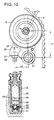
- the present inventor considered using the above equation (1) to obtain an autotensioner of small size and also having a good performance, and therefore made an investigation to determine the appropriateness of controlling the dimensions of a damper unit for an autotensioner according to equation (1). This investigation was carried out based on the measured values given in the beforementioned Tables 1 to 3 and Figs.8 to 10. In carrying out this investigation, an autotensioner such as shown in Fig.14 (similar to that of Figs.3 to 5) was prepared.
- the computed values for the half amplitude are shown respectively in Figs.8 to 10 by the broken line.
- the autotensioner fitted with the damper unit 34 having dimensions corresponding to the symbols O is an embodiment of the present invention, while the autotensioner fitted with the damper unit 34 having dimensions corresponding to the symbols X, is a comparative example outside of the technical range of the present invention, as mentioned before.
- the width (h) of the leak gap 58 (Fig.13) between the inner peripheral face of the cylinder 39 and the outer peripheral face of the piston 40 in the damper unit 34 is controlled to within a predetermined range according to the equation obtained as above, then a small size unit with exceptional damping performance can be used for the damper unit 34. Therefore the autotensioner of the present invention, in spite of being small and thus facilitating installation into a limited engine space, is very effective in preventing oscillation of the timing belt 2.
- a feature of this autotensioner is that the width (h) of the leak gap 58 between the inner peripheral face of the cylinder 39 and the outer peripheral face of the piston 40 in the damper unit 34, is controlled as described above, within a predetermined range.
- the present invention is not limited to the autotensioner of the construction shown in Figs.3 to 5 used in the experiments, but is also applicable to constructions such as disclosed in the beforementioned various publications.
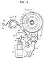
- Figs.15 and 16 show a construction disclosed in Japanese Utility Model First Publication KOKAI No. H6-87758 for a first example capable of embodying the present invention.
- the characteristic of the construction in Figs.15 and 16 is that in order to simplify construction, the seating portion, shape and construction of the damper unit 34a are devised so that the fixed member 14 of the conventional construction shown in Figs.3 to 5 can be omitted.
- the construction and operation of the other parts are similar to the conventional construction shown in Figs.3 to 5 and hence similar parts are indicated with the same symbol and repeated description is omitted or abbreviated. As follows is a description focusing on the characteristic points of the construction of the first example.
- a swinging member 18 is pivotally supported directly on a fixed portion 59, such as the front face of the cylinder block rather than through the fixed member 14 (Figs.3 to 5).
- a bolt or first shaft 21 is inserted into a cylindrical portion 19 formed on the base end (bottom end in Figs.15 to 16) of the swinging member 18.
- a plain bearing 20 is provided.
- An engaging portion 30a of a torsion coil spring 28 is engaged in an engaging hole 31a formed in the fixed portion 59.
- a resilient force is applied to the swinging member 18 by the torsion coil spring 28 so as to turn in a clockwise direction in Fig.15 about the bolt 21.
- engagement can be by way of an engagement lug such as an engagement groove or a pin provided on the fixed portion 59.
- a cavity 36a Formed in a swinging arm 35 provided on the swinging member 18 is a cavity 36a into which is fitted a damper unit 34a.
- a protruding lug 61 is provided on a part of the fixed portion 59 away from the bolt 21, such that an outer end of the damper unit 34a is faced to an end face of the lug 61.
- the diameter of the plunger 38a is bigger than that of the damper unit 34 shown in Fig.6.
- the cylinder 39 is inserted slidingly in the cavity 36a in an axial direction with the plunger 38a inserted deep into the cavity 36a. Moreover, the bottom face of the cylinder 39 is abutted against the protruding lug 61. Therefore, with the swinging or pivoting of the swinging member 18, the end portion of the cylinder 39 moves in a direction so as to protrude from the cavity 36a.
- the autotensioner shown in Figs. 15 and 16 constructed as described above, since the fixed member 14 (Figs.3 to 5) is omitted, the overall body of the autotensioner can be made small and light weight. As a result, the autotensioner can be fitted into a narrower location space.
- Figs.19 and 20 show a second example of the constructions capable of embodying the present invention.
- the characteristic of the construction in Figs.19 and 20 is that, the installation location for the torsion coil spring 28 is regulated in relation to the swinging member 18 in order to increase the amount of freedom of design of the engine fitted with the autotensioner.
- the construction and operation of the other parts are similar to the beforementioned conventional construction shown in Figs.3 to 5 and hence similar parts are indicated with the same symbol and repeated description is omitted. As follows is a description focusing on the characteristic points of the construction of the second example.
- a retaining tube 62 is fixed to the front face of the cylinder block on which the autotensioner is mounted, at a location radially outwards from the fixed shaft 17 by an amount more than the size of the swinging member 18 in that direction.
- This retaining tube 62 is parallel with the fixed shaft 17.
- An engagement pin 63 is fixed to a portion on the front face of the cylinder block away from the retaining tube 62. The engagement pin 63 also is parallel with the fixed shaft 17.
- an attachment plate to which the retaining tube 62 and engagement pin 63 are fitted may be fixed to the front face of the cylinder block.
- a coil portion 29 of the torsion coil spring 28 is fitted loosely around the periphery of the retaining tube 62.
- a first engaging portion 64 parallel with the retaining tube 62 is formed in one end of the torsion coil spring 28 (right lower end in Fig.19), while a second engaging portion 65 bent into an L shape is formed in the other end (left end in Fig.19).
- the first engaging portion 64 is inserted into an engaging hole 66 formed in the swinging member 18, while the second engaging portion 65 is engaged with the engagement pin 63. In this condition, a resilient force is applied to the swinging member 18 so as to swing in a clockwise direction in Fig.19 about the fixed shaft 17.
- the coil portion 29 of the torsion coil spring 28 is located at a portion separated in a radially outward direction of the fixed shaft 17 from the swinging member 18, then the degree of freedom in assembling the swinging member 18 and the torsion coil spring 28 is increased. That is to say, when as with the conventional construction shown in Figs.3 to 5 and the construction of the first example shown in Figs.15 to 18, the coil portion 29 of the torsion coil spring 28 is located around the fixed shaft 17, then the assembly location for the torsion coil spring 28 and the swinging member 18 is necessarily determined. In contrast to this, if the coil portion 29 is located at a portion separated from the swinging member 18, then there are a number of possible assembly locations for the torsion coil spring 28 and the swinging member 18.
- Fig.21 again shows a third example of the constructions capable of embodying the present invention.
- the retaining tube 62 for supporting the coil portion 29 of the torsion coil spring 28 is provided on the other side of the pulley 5 with respect to the fixed shaft 17.
- a cut-out 68 is formed in a part of the swinging member 18, and the first engaging portion 64 of the torsion coil spring 28 is engaged in this cut-out 68.
- a bearing block 37 is fixed to the front face of an attachment plate 69 together with the retaining tube 62 and the engagement pin 63.
- a stopper pin 46 spans between the attachment plate 69 and the swinging member 18.
- Other details of construction and operation are the same as for the abovementioned second embodiment.
- Fig.22 again shown a fourth example of the constructions capable of embodying the present invention.
- the fixed shaft 17 and the bearing block 37 are fixed to the front face (upper face in Fig.22) of an attachment plate 69 fixed to the front face of a cylinder block 70.
- the swinging member 18 is pivotally supported on the tip half portion (upper half portion in Fig.22) of the fixed shaft 17, such that it is externally fitted to a plain bearing, so that it may be retained or removed from the fixed shaft 17 by tightening or removing a bolt 21.
- the coil portion 29 of the torsion coil spring 28 is fitted loosely over a boss portion 71 of the attachment plate 69.
- the boss portion 71 surrounds a base half portion of the fixed shaft 17, with a diameter larger than the tip half portion.
- the first engaging portion 64 of the torsion coil spring 28 is engaged in an engagement hole formed in the swinging member 18, while the second engaging portion 65 is engaged with an engagement pin 63 fixed to the attachment plate 69.
- the coil portion 29 of the torsion coil spring 28 and the swinging member 18 is provided around the fixed shaft 17 and displaced axially from each other (up / down direction in Fig.22; in the actual situation, horizontally at right angles to the front face of the cylinder block 70). Therefore even if the coil portion 29 is of large diameter, there is no interference between the coil portion 29 and the swinging member 18. As a result, as with the beforementioned second and third examples, installation in a more limited space is possible, giving an increase in the degree of freedom in design of an engine fitted with the autotensioner.
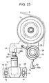
- Figs.23 and 24 show a fifth example of the constructions capable of embodying the present invention.
- the characteristic of the construction of this fifth example is that in order for the damper unit 34 to function reliably, the attachment location for the damper unit 34 is made adjustable in the direction of extension and contraction.
- the construction and operation of the other parts are similar to the beforementioned conventional construction shown in Figs.3 to 5 and the construction of the Examples 1 to 4, and hence similar parts are indicated with the same symbol and repeated description is omitted. As follows is a description focusing on the characteristic points of the construction of the fifth example.
- the fixed shaft 17 and an engagement pin 63 are supportingly fixed on the front face of the engine cylinder block (fixed portion) either directly or by way of an attachment plate.
- the engagement pin 63 and a holder 72 are provided instead of the fixed member 14 as with the conventional construction shown in Fig.3 to 5.
- Engaging portions 30a, 30b are provided at both ends of the torsion coil spring 28 to apply the tension force. The engaging portion 30a is engaged with the engagement pin 63.
- a retaining portion 73 having an upward opening is provided in a central portion of the holder 72, for engagingly supporting the lower end portion of the damper unit 34.
- a pair of attachment flanges 74 are provided on both sides of the retaining portion 73.
- Elongated holes 81 extending in the vertical direction (direction of extension and contraction of the damper unit 34) are formed in the flanges 74.
- the holder 72 is fixed to the front face of the engine cylinder block or fixed portion by means of attachment bolts 75 passing through the elongated holes 81, either directly or by way of an attachment plate.
- Engine assembly of the autotensioner of the fifth example shown in Fig.23 and constructed as described above is carried out as follows.
- the timing belt 2 is fitted around the pulley 5 which is pivotally supported on the tip end portion of the swinging member 18.
- the swinging member 18 is displaced against the resilient force of the torsion coil spring 28 in the counter clockwise direction of Fig.23, using an appropriate tool.
- the force applied to the swinging member 18 by the tool is removed, so that the pulley 5 is pressed against the timing belt 2 under the resilient force of the torsion coil spring 28.
- a tension corresponding to the resilient force of the torsion coil spring 28 is applied to the timing belt 2 irrespective of any differences in the length of the timing belt 2 due for example to manufacturing errors.
- timing belt 2 on the pulley 5 in the state where the engaging portion 30a at one end of the torsion coil spring 28 is not engaged with the engagement pin 63, so that the resilient force due to the torsion coil spring 28 is not applied to the swinging member 18, and then to engage the engaging portion 30a with the engagement pin 63 so that the resilient force is applied to the timing belt 2.
- the holder 72 accommodating the bottom end of the damper unit 34, is attached below the swinging arm 35 of the swinging member 18 using the attachment bolts 75.
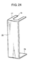
- the damper unit 34 is fitted in the fully contracted condition using a stopper member 76 such as shown in Fig.24.
- the stopper member 76 is made by bending opposite ends of a metal plate of sufficient rigidity, at right angles in the same direction to give an upper plate 77 and lower plate 78, with a cut out 79 formed in the upper plate 77.
- the bottom plate 78 is abutted against the lower face of the holder 72 at the same time that the cut-out 79 is engaged with the neck portion 80 of the plunger 38 of the damper unit 34, so that the damper unit 34 is held in a fully contracted condition.
- the attachment location of the holder 72 is adjusted so that the upper end portion of the plunger 38 is abutted against the lower face of the bearing block 37 supported on the swinging arm 35.
- the attachment bolts 75 are left in the untightened condition. Accordingly, the vertical location of the holder 72 and the damper unit 34 can be freely adjusted by the amount of free movement of the attachment bolts 75 along the elongated holes 81, enabling the upper end of the plunger 38 and the lower face of the bearing block 37 to be positively abutted together.
- the attachment bolts 75 are tightened to thereby fix the holder 72 to the front face of the cylinder block.
- the stopper member 76 is removed. With removal of the stopper member 76, the plunger 38 of the damper unit 34 rises under the resilient force of the biasing spring 41 (Fig.6), so that the upper end of the plunger 38 is pressed against the lower face of the bearing block 37 under the resilient force of the biasing spring 41.
- the damper unit 34 tends to extend and is thus reliably braced between the bearing block 37 provided on the swinging member 18, and the fixed portion or holder 72 fixed to the front face of the cylinder block.
- Fig.25 again shows a construction a sixth example of the constructions capable of embodying the present invention.
- the holder 72 is fixed to the swinging member 18 by means of the attachment bolts 75 passing through the pair of elongated holes 81 on the left and right sides of the holder 72, while the bearing block 37 is fixed to the front face of the cylinder block.
- Other details of construction and operation are the same as for the abovementioned fifth example.
- the cylindrical portion 19 of the swinging member 18 is externally fitted to the non rotating, fixed shaft 17, so that the swinging member 18 is swung or pivoted with rotation of the cylindrical portion 19.
- a shaft can be fixed to the swinging member 18, and a cylindrical portion fixed to the fixed portion or fixed member 14, so that the swinging member 18 is swung or pivoted with rotation of the shaft.
- the autotensioner of the present invention is constructed and used as described above, sufficient damper performance can be maintained, and oscillations of the timing belt effectively prevented. Moreover, the life of the timing belt can be sufficiently maintained. Furthermore, small size construction is possible, enabling the unit to be installed in the limited space of the engine cylinder block, so that the degree of freedom in engine design is improved.
Landscapes
- Engineering & Computer Science (AREA)
- General Engineering & Computer Science (AREA)
- Mechanical Engineering (AREA)
- Devices For Conveying Motion By Means Of Endless Flexible Members (AREA)
Claims (8)
- Automatische Spannvorrichtung zum Aufbringen einer geeigneten Spannung auf einen Steuerriemen in einem Fahrzeugmotor, die aufweist:eine erste Welle (17, 21), die gelagert ist an einem Befestigungsabschnitt (59, 69) direkt oder durch ein Befestigungselement (14), das an dem Befestigungsabschnitt (59, 69) befestigt ist,ein Schwingelement (18), das frei um die erste Welle (17, 21) schwingt,eine zweite Welle (22), die parallel zu der ersten Welle (17, 21) und an einem Teil des Schwingelements (18) von der ersten Welle (17, 21) getrennt vorgesehen ist,eine Riemenscheibe (5), die derart gelagert ist, daß sie frei drehbar um die zweite Welle (22) ist,eine Spannfeder (28), die zwischen dem Befestigungsabschnitt (59, 69) oder dem Befestigungselement (14) und dem Schwingelement (18) vorgesehen ist, um einen Widerstand gegen Versetzen des Schwingelements (18) vorzusehen, um die Riemenscheibe (5) auf den Steuerriemen (2) zu pressen, undeine Dämpfereinheit (34, 34a), die zwischen dem Befestigungsabschnitt (59, 69) oder dem Befestigungselement (14) und dem Schwingelement (18) vorgesehen ist, um einen Widerstand gegen Versetzen des Schwingelements (18) gegen die elastische Kraft der Spannfeder (28) vorzusehen,die Dämpfereinheit (34, 34a) weist auf, einen Zylinder (39), in dem eine viskose Flüssigkeit (12) dicht eingeschlossen ist, einen Kolben (40), mit axialen Endflächen, der im Inneren des Zylinders (39) angeordnet ist, so daß er in seiner axialen Richtung bewegbar ist, eine Druckfeder (41), die zwischen dem Kolben (40) und dem Zylinder (39) vorgesehen ist, um den Kolben (40) in eine Richtung zu drücken, einen Plunger (38, 38a), der abnehmend von dem Zylinder (39), mit Abstand von dem Kolben (40) unter einer elastischen Kraft der Druckfeder (41) hervorsteht, einen Ölkanal (42) zur Verbindung beider axialen Endflächen des Kolbens (40) miteinander, und ein Rückschlagventil (45), das in Serie mit dem Ölkanal (42) vorgesehen ist und ausgebildet ist, um nur dann zu öffnen, wenn der Kolben (40) unter der elastischen Kraft der Druckfeder (41) vesetzt wird, die Druckfeder (28) ist außerhalb des Zylinders (39) vorgesehen, die automatische Spannvorrichtung weist die Abmessungen, wie im folgenden angegeben, auf, wobei
- r
- einen inneren Durchmesser (mm) des Zylinders (39) repräsentiert,
- d
- einen äußeren Durchmesser (mm) des Kolbens (40) repräsentiert,
- h
- einen Leckspalt (mm) zwischen dem Zylinder (39) und dem Kolben (40) repräsentiert, wobei die Breite (h) des Leckspalts die halbe Differenz zwischen dem inneren Durchmesser (r) des Zylinders (39) und dem äußeren Durchmesser (d) des Kolbens (40) ist, so daß h = (r - d)/2 ist,
- m1
- die totale schwingende inertiale Masse (kg) des Schwingelements (18) und der Elemente (5, 23-27), welche zusammen mit dem Schwingelement (18) schwingen repräsentiert,
- m2
- die gesamte inertiale Masse (kg) der Elemente (38, 38a, 40), welche sich axial innerhalb des Zylinders (39) mit der Entspannung und Kontraktion der Dämpfereinheit (34, 34a) bewegen, repräsentiert,
- ν
- eine kinematische Viskosität (mm2/s) der viskosen Flüssigkeit (12) unter Betriebsbedingungen der automatischen Spannvorrichtung repräsentiert,
- ρ
- die Dichte (kg/mm3) der viskosen Flüssigkeit (12) unter den Betriebsbedingungen der automatischen Spannvorrichtung repräsentiert,
- L
- eine axiale Länge (mm) des schmalen Leckspalts, der zwischen der inneren peripheren Fläche des Zylinders (39) und der äußeren peripheren Fläche des Kolbens (40) existiert, repräsentiert,
- K1
- die Federkonstante (kg/s2) der Spannfeder (28) repräsentiert,
- K2
- die Federkonstante (kg/s2) der Druckfeder (41) repräsentiert,
- B1, B2, B4
- Bewegungsrichtungskoeffizienten für das Versetzen zwischen der Riemenscheibe (5) und der Dämpfereinheit (34, 34a) bezüglich dem Schwingelement (18) repräsentieren,
- B3
- einen Bewegungsrichtungskoeffizienten für das Versetzen zwischen der Riemenscheibe (5) und der Spannfeder (28) bezüglich dem Schwingelement (18) repräsentiert,
- a
- eine Halbamplitude (kg mm/s2) von Fluktationen in der Eingangsbelastung auf die Riemenscheibe (5) entsprechend der Spannungsfluktuationen in dem Steuerriemen (2) unter Betriebsbedingungen, repräsentiert,
- f
- eine Frequenz (Hz) der Oszillation des Steuerriemens (2), welcher am bedeutendsten unter Betriebsbedingungen sind, repräsentiert,
- t
- Zeit (s) repräsentiert,
- x
- das Versetzen (mm) der Riemenscheibe (5) gemäß der Oszillation in dem Steuerriemen (2) repräsentiert,
- dx/dt
- eine Versetzungsänderung (mm/s) der Riemenscheibe (5) gemäß der Oszillationen in dem Steuerriemen (2) repräsentiert,
- d2x/dt2
- eine Versetzungsbeschleunigung (mm/s2) der Riemenscheibe gemäß der Oszillationen in dem Steuerriemen (2) repräsentiert, und
- y
- die Riemenscheibe (5) Versetzungsbreite (mm) gemäß der Oszillationen in dem Steuerriemen (2) repräsentiert,
- h1
- den Leckspalt (mm), wenn (y/2) 0,7 mm ist, repräsentiert, und
- h2
- den Leckspalt (mm), wenn (y/2) 0,05 mm ist, repräsentiert, wobei die Breite (h)
durch die folgende Gleichung bestimmt ist und spezifiziert ist zwischen (h1) und
(h2), und gleich oder größer als 0,002 mm ist:
- Automatische Spannvorrichtung gemäß Anspruch 1, wobei der Motor einen Zylinderblock (70) mit einer Fronffläche aufweist, der Befestigungsabschnitt (59, 69) an der Frontfläche des Zylinderblocks vorgesehen ist, das Befestigungselement (14) einen Befestigungsarmabschnitt aufweist, welcher an dem Befestigungsabschnitt (59, 69) an der Fronffläche des Zylinderblocks an einer Position getrennt von der ersten Welle (17, 21) befestigt ist, das Schwingelement (18) einen zylindrischen Abschnitt (19), der an der ersten Welle (17, 21) angeordnet ist, und einem Schwingarmabschnitt, der beabstandet von der zweiten Welle ist, aufweist, und die Dämpfereinheit (34, 34a) zwischen dem Befestigungsarmabschnitt des Befestigungselements (14) und dem Schwingarmabschnitt des Schwingelements (18) vorgesehen ist.
- Automatische Spannvorrichtung gemäß Anspruch 2, wobei das Befestigungselement (14) ein Eingriffsloch (31a) zwischen der ersten Welle (17, 21) und dem Befestigungsarmabschnitt aufweist, das Schwingelement (18) ein Eingriffsloch (31b) zwischen der zweiten Welle (22) und dem Schwingarmabschnitt aufweist, und die Spannfeder (28) ist eine Torsionsschraubenfeder ist mit einem Schraubenabschnitt (29), der zwischen dem zylindrischen Abschnitt (19) des Schwingelements (18) vorgesehen ist, ein erster Eingriffsabschnitt (30b) in dem Eingriffsloch (31b) des Schwingelements (18) gesichert ist und ein zweiter Eingriffsabschnitt (30a) in dem Eingriffsloch (31a) des Befestigungselements (14) gesichert ist.
- Automatische Spannvorrichtung gemäß Anspruch 2, wobei die Spannfeder (28) eine Torsionsschraubenfeder ist, die einen Schraubenabschnitt (29) radial nach außen beabstandet von dem Schwingelement (18) bezüglich der ersten Welle (17, 21) aufweist.
- Automatische Spannvorrichtung gemäß Anspruch 4, wobei das Schwingelement (18) ein Eingriffsloch (66) zwischen der zweiten Welle (22) und dem Schwingarmabschnitt aufweist, die Spannfeder (28) einen ersten Eingriffsabschnitt (64) aufweist, der durch das Eingriffsloch (66) des Schwingelements (18) gesichert ist, ein zweiter Eingriffsabschnitt (65) durch einen Eingriffsstift (63) gesichert ist, welcher in dem Befestigungsabschnitt (59, 69) des Zylinderblocks (70) vorgesehen ist und ein Schraubenabschnitt (29) in einer Lagerröhre (62) in dem Befestigungsabschnitt (59, 69) des Zylinderblocks vorgesehen ist.
- Automatische Spannvorrichtung gemäß Anspruch 4, wobei das Schwingelement (18) eine Aussparung (68) aufweist, und die Spannfeder (28) einen ersten Eingriffsabschnitt (64) aufweist, der durch die Aussparung (68) des Schwingelements (18) gesichert ist, ein zweiter Eingriffsabschnitt (65) durch einen Eingriffsstift (63) gesichert ist, der in dem Befestigungsabschnitt (59, 69) des Zylinderblocks (70) vorgesehen ist, und ein Schraubenabschnitt (29) ist in einer Lagerröhre (62) an einer gegenüberliegenden Seite der Riemenscheibe (5) bezüglich der ersten Welle (17) des Befestigungsabschnitts (59, 69) des Zylinderblocks vorgesehen ist.
- Automatische Spannvorrichtung gemäß Anspruch 1, wobei der Motor einen Zylinderblock mit einer Frontfläche aufweist, so daß der Befestigungsabschnitt (59) an der Fronffläche des Zylinderblocks vorgesehen ist, die erste Welle (21) eine Schraube ist und direkt an dem Befestigungsabschnitt (59) an der Fronffläche des Zylinderblocks gesichert ist, das Schwingelement (18) einen zylindrischen Abschnitt (19) umfaßt, der an der ersten Welle (21) angeordnet ist, ein Schwingarmabschnitt beabstandet von der zweiten Welle (22) ist, und ein Eingriffsloch ist zwischen der zweiten Welle (22) und dem Schwingarmabschnitt vorgesehen ist, die Spannfeder (28) eine Torsionsschraubenfeder ist und einen Schraubenabschnitt (29) aufweist, der in dem zylindrischen Abschnitt (19) des Schwingelements (18) angeordnet ist, ein erster Eingriffsabschnitt (30a), in dem Eingriffsloch (31a) gesichert ist, das in dem Befestigungsabschnitt (59) des Zylinderblocks ausgebildet ist, und ein zweiter Eingriffsabschnitt (30b) in dem Eingriffsloch des Schwingelements (18) gesichert ist, und die Dämpfereinheit (34a) zwischen dem Befestigungsabschnitt (59) des Zylinderblocks und des Schwingarmabschnitts des Schwingelements (18) vorgesehen ist.
- Automatische Spannvorrichtung gemäß Anspruch 1, wobei der Motor einen Zylinderblock mit einer Frontfläche aufweist, so daß der Befestigungsabschnitt an der Fronffläche des Zylinderblocks vorgesehen ist, die erste Welle gesichert gelagert ist an der Frontfläche des Zylinderblocks des Motors, die Dämpfereinheit (34) zwischen dem Befestigungsabschnitt des Schwingelements (18) vorgesehen ist und durch einen Halter (72) gelagert ist, der durch das Schwingelement oder das Befestigungselement gesichert gelagert ist, und der Halter (72) ein Langloch (81) verlängert in der Expansionsund Kontraktionsrichtung der Dämpfereinheit (34) aufweist, und durch eine Montageschraube (75), die durch das Langloch (81) geführt ist, angezogen ist.
Applications Claiming Priority (2)
| Application Number | Priority Date | Filing Date | Title |
|---|---|---|---|
| JP20685894A JP3411101B2 (ja) | 1994-08-31 | 1994-08-31 | オートテンショナ |
| JP206858/94 | 1994-08-31 |
Publications (2)
| Publication Number | Publication Date |
|---|---|
| EP0699848A1 EP0699848A1 (de) | 1996-03-06 |
| EP0699848B1 true EP0699848B1 (de) | 1998-11-25 |
Family
ID=16530218
Family Applications (1)
| Application Number | Title | Priority Date | Filing Date |
|---|---|---|---|
| EP95113640A Expired - Lifetime EP0699848B1 (de) | 1994-08-31 | 1995-08-30 | Automatische Spannvorrichtung für endlose, flexible Antriebsmittel |
Country Status (5)
| Country | Link |
|---|---|
| US (1) | US5632698A (de) |
| EP (1) | EP0699848B1 (de) |
| JP (1) | JP3411101B2 (de) |
| KR (1) | KR0180345B1 (de) |
| DE (1) | DE69506198T2 (de) |
Families Citing this family (19)
| Publication number | Priority date | Publication date | Assignee | Title |
|---|---|---|---|---|
| DE19717360A1 (de) * | 1996-04-29 | 1997-10-30 | Borg Warner Automotive | Hydraulischer Kettenspanner |
| EP0846891A1 (de) * | 1996-12-05 | 1998-06-10 | Borg-Warner Automotive, Inc. | Hydraulischer Spanner mit Kolben und Gehäuse aus Kunststoff |
| NL1011625C2 (nl) * | 1999-03-22 | 2000-09-27 | Skf Engineering & Res Services | Werkwijze voor het regelen van een band-poelie-aandrijfsysteem, alsmede band-poelie-aandrijfsysteem. |
| KR100349250B1 (ko) * | 2000-04-11 | 2002-08-21 | 주식회사 만도 | 자동차 스티어링 칼럼의 틸팅장치용 복원스프링 |
| DE10031610A1 (de) | 2000-06-29 | 2002-02-07 | Schaeffler Waelzlager Ohg | Kettenspanner |
| JP2003202060A (ja) * | 2001-11-02 | 2003-07-18 | Ntn Corp | チェーンテンショナ |
| AU2003297008B2 (en) * | 2002-12-16 | 2008-05-08 | The Gates Corporation (A Delaware, U.S.A. Corporation) | Active tensioner |
| US7850559B2 (en) * | 2004-10-26 | 2010-12-14 | Schaeffler Technologies Gmbh & Co. Kg | Hydraulic tensioning system |
| WO2006105656A1 (en) * | 2005-04-08 | 2006-10-12 | Litens Automotive Partnership | Tensioner with molded arm |
| JP2006350720A (ja) * | 2005-06-16 | 2006-12-28 | Ntn Corp | オートテンショナのブラケット形状設計方法 |
| DE102005056417A1 (de) * | 2005-11-26 | 2007-05-31 | Schaeffler Kg | Spannvorrichtung zum Spannen eines Antriebsriemens beziehungsweise einer Antriebskette |
| DE102007039134A1 (de) * | 2007-08-18 | 2009-02-19 | Schaeffler Kg | Spanneinrichtung für ein Zugmittel |
| DE102007000750A1 (de) * | 2007-09-20 | 2009-04-09 | Hilti Aktiengesellschaft | Handwerkzeugmaschine mit Riemenspannvorrichtung |
| US20110269585A1 (en) * | 2010-05-03 | 2011-11-03 | Gong Shun Technology Co., Ltd. | Tension regulator with a pressure vessel applied to a timing belt |
| US8690109B2 (en) | 2011-08-03 | 2014-04-08 | Haworth, Inc. | Automatic gap adjustor |
| JP6659454B2 (ja) * | 2016-05-13 | 2020-03-04 | Ntn株式会社 | オートテンショナ |
| DE102016221797B4 (de) * | 2016-11-08 | 2020-03-26 | Schaeffler Technologies AG & Co. KG | Spannvorrichtung |
| IT201600130235A1 (it) * | 2016-12-22 | 2018-06-22 | Dayco Europe Srl | Tenditore sensorizzato |
| JP2024073910A (ja) * | 2022-11-18 | 2024-05-30 | 株式会社椿本チエイン | チェーンテンショナ |
Family Cites Families (30)
| Publication number | Priority date | Publication date | Assignee | Title |
|---|---|---|---|---|
| US3722640A (en) * | 1971-03-26 | 1973-03-27 | Paul H Taylor | Fluid amplified liquid spring shock absorbers with improved piston heads |
| FR2425018A1 (fr) * | 1978-05-05 | 1979-11-30 | Bourcier Carbon Christian | Perfectionnement aux pistons pour amortisseurs |
| US4411638A (en) * | 1981-08-27 | 1983-10-25 | Dayco Corporation | Belt tensioner and method of making the same |
| JPS58121344A (ja) * | 1982-01-12 | 1983-07-19 | Toyota Motor Corp | ベルト用のオ−トテンシヨナ |
| JPS59126144A (ja) * | 1982-12-31 | 1984-07-20 | Aisin Seiki Co Ltd | 密封式オ−トテンシヨナ |
| JPS6023355A (ja) * | 1983-07-15 | 1985-02-05 | Ube Ind Ltd | 3−フエニル−2−アミノ−2−メチルプロピオン酸アミド類の製造法 |
| JPS61294250A (ja) * | 1985-06-20 | 1986-12-25 | Fuji Heavy Ind Ltd | ハイドロリツクアジヤスタ装置 |
| JPS61294249A (ja) * | 1985-06-20 | 1986-12-25 | Fuji Heavy Ind Ltd | ハイドロリツクアジヤスタ装置 |
| JPS62274144A (ja) * | 1986-05-20 | 1987-11-28 | Honda Motor Co Ltd | 油圧式オ−トテンシヨナ |
| JP2525578B2 (ja) * | 1986-05-20 | 1996-08-21 | 本田技研工業株式会社 | ベルトテンシヨナ |
| JPS62271910A (ja) * | 1986-05-20 | 1987-11-26 | Honda Motor Co Ltd | ダブルオ−バヘツドカム型エンジンにおけるカムシヤフト駆動装置 |
| JPS62274142A (ja) * | 1986-05-21 | 1987-11-28 | Honda Motor Co Ltd | 油圧式オ−トテンシヨナ |
| JPS6348842A (ja) * | 1986-08-19 | 1988-03-01 | Mitsubishi Electric Corp | 半導体集積回路装置の製造方法 |
| US4838839A (en) * | 1987-01-19 | 1989-06-13 | Nippon Seiko Kabushiki Kaisha | Multi-disk fluid viscosity type auto-tensioner |
| JPH0810020B2 (ja) * | 1987-01-19 | 1996-01-31 | 日本精工株式会社 | 多板式流体粘性型オ−トテンシヨナ− |
| JPH01100953A (ja) * | 1987-10-14 | 1989-04-19 | Toshiba Corp | Ic用ソケット |
| GB2221279B (en) * | 1988-07-22 | 1992-07-29 | Ntn Toyo Bearing Co Ltd | Belt autotensioner |
| DE3828350A1 (de) * | 1988-08-20 | 1990-03-01 | Skf Gmbh | Automatische spannvorrichtung |
| JPH0349453U (de) * | 1989-09-22 | 1991-05-14 | ||
| JPH0417543A (ja) * | 1990-05-08 | 1992-01-22 | Toshiba Corp | 回転電気機械の巻線固定装置 |
| JP2507172Y2 (ja) * | 1990-05-31 | 1996-08-14 | 株式会社椿本チエイン | 逆止弁を具えた歯付ベルト用テンショナ |
| DE4202167C2 (de) * | 1991-01-31 | 1996-11-28 | Ntn Toyo Bearing Co Ltd | Riemenspanneinrichtung |
| JP2560655Y2 (ja) * | 1991-01-31 | 1998-01-26 | エヌティエヌ株式会社 | オートテンショナ |
| JPH058098U (ja) * | 1991-07-11 | 1993-02-02 | エヌテイエヌ株式会社 | ベルト張力調整装置 |
| JP2578034B2 (ja) * | 1991-08-12 | 1997-02-05 | 株式会社キトー | 車輪の熱処理方法 |
| FR2693905B1 (fr) * | 1992-07-27 | 1994-09-02 | Rhone Merieux | Procédé de préparation de microsphères pour la libération prolongée de l'hormone LHRH et ses analogues, microsphères et formulations obtenues. |
| JPH0647757A (ja) * | 1992-07-31 | 1994-02-22 | Olympus Optical Co Ltd | 複合型光学素子の製造方法及び装置 |
| GB2287519A (en) * | 1992-09-03 | 1995-09-20 | Nsk Ltd | Auto tensioner |
| US5352160A (en) * | 1992-09-03 | 1994-10-04 | Nsk Ltd. | Auto tensioner |
| JPH0647757U (ja) * | 1992-09-03 | 1994-06-28 | 日本精工株式会社 | オートテンショナ |
-
1994
- 1994-08-31 JP JP20685894A patent/JP3411101B2/ja not_active Expired - Fee Related
-
1995
- 1995-08-30 DE DE69506198T patent/DE69506198T2/de not_active Expired - Fee Related
- 1995-08-30 EP EP95113640A patent/EP0699848B1/de not_active Expired - Lifetime
- 1995-08-31 US US08/521,722 patent/US5632698A/en not_active Expired - Lifetime
- 1995-08-31 KR KR1019950028046A patent/KR0180345B1/ko not_active Expired - Fee Related
Also Published As
| Publication number | Publication date |
|---|---|
| DE69506198T2 (de) | 1999-04-15 |
| EP0699848A1 (de) | 1996-03-06 |
| DE69506198D1 (de) | 1999-01-07 |
| JPH0874953A (ja) | 1996-03-19 |
| JP3411101B2 (ja) | 2003-05-26 |
| US5632698A (en) | 1997-05-27 |
| KR960008122A (ko) | 1996-03-22 |
| KR0180345B1 (ko) | 1999-04-01 |
Similar Documents
| Publication | Publication Date | Title |
|---|---|---|
| EP0699848B1 (de) | Automatische Spannvorrichtung für endlose, flexible Antriebsmittel | |
| CA2308567C (en) | Rotary belt tensioner with hydraulic damping | |
| AU631336B2 (en) | Belt tensioner | |
| KR100208042B1 (ko) | 장력 조절 장치용 감쇠 기구 | |
| RU2304241C2 (ru) | Натяжное устройство механической ременной передачи, механический привод, а также способ натяжения приводного ремня | |
| US6142115A (en) | Vibration damper for the crankshaft of a piston engine | |
| US4739866A (en) | Apparatus for damping torsional vibrations in the power trains of motor vehicles | |
| KR20040011509A (ko) | 비대칭 감쇠 텐셔너 벨트 구동 시스템 | |
| GB2267325A (en) | Autotensioner | |
| US4601683A (en) | Belt tensioner, part therefor and methods of making the same | |
| US4966571A (en) | Internal combustion engine | |
| EP0687835B1 (de) | Riemenspanner mit Schwingungsdämpfung | |
| US5458542A (en) | Auto tensioner | |
| AU559553B2 (en) | Belt tensioner, part therefor, and methods of making the same | |
| US20070010361A1 (en) | Belt tensioning device with external damping sleeve | |
| EP0120069A1 (de) | Riemenspanner. | |
| JPH0526056B2 (de) | ||
| JPH0276957A (ja) | オートテンショナ | |
| JP2000179623A (ja) | ダンパ装置 | |
| JPH0647757U (ja) | オートテンショナ | |
| JPH04347042A (ja) | オートテンショナ | |
| JPH01120469A (ja) | ベルト用オートテンショナ | |
| KR20040046583A (ko) | 밸런스 웨이트 | |
| JPH0634003A (ja) | オートテンショナ | |
| KR19990032016A (ko) | 듀얼 모드 댐퍼 풀리 |
Legal Events
| Date | Code | Title | Description |
|---|---|---|---|
| PUAI | Public reference made under article 153(3) epc to a published international application that has entered the european phase |
Free format text: ORIGINAL CODE: 0009012 |
|
| 17P | Request for examination filed |
Effective date: 19950830 |
|
| AK | Designated contracting states |
Kind code of ref document: A1 Designated state(s): DE FR GB |
|
| 17Q | First examination report despatched |
Effective date: 19970516 |
|
| GRAG | Despatch of communication of intention to grant |
Free format text: ORIGINAL CODE: EPIDOS AGRA |
|
| GRAG | Despatch of communication of intention to grant |
Free format text: ORIGINAL CODE: EPIDOS AGRA |
|
| GRAH | Despatch of communication of intention to grant a patent |
Free format text: ORIGINAL CODE: EPIDOS IGRA |
|
| GRAH | Despatch of communication of intention to grant a patent |
Free format text: ORIGINAL CODE: EPIDOS IGRA |
|
| GRAA | (expected) grant |
Free format text: ORIGINAL CODE: 0009210 |
|
| AK | Designated contracting states |
Kind code of ref document: B1 Designated state(s): DE FR GB |
|
| REF | Corresponds to: |
Ref document number: 69506198 Country of ref document: DE Date of ref document: 19990107 |
|
| ET | Fr: translation filed | ||
| PG25 | Lapsed in a contracting state [announced via postgrant information from national office to epo] |
Ref country code: GB Free format text: LAPSE BECAUSE OF NON-PAYMENT OF DUE FEES Effective date: 19990830 |
|
| PLBE | No opposition filed within time limit |
Free format text: ORIGINAL CODE: 0009261 |
|
| STAA | Information on the status of an ep patent application or granted ep patent |
Free format text: STATUS: NO OPPOSITION FILED WITHIN TIME LIMIT |
|
| 26N | No opposition filed | ||
| GBPC | Gb: european patent ceased through non-payment of renewal fee |
Effective date: 19990830 |
|
| PG25 | Lapsed in a contracting state [announced via postgrant information from national office to epo] |
Ref country code: FR Free format text: LAPSE BECAUSE OF NON-PAYMENT OF DUE FEES Effective date: 20000428 |
|
| PG25 | Lapsed in a contracting state [announced via postgrant information from national office to epo] |
Ref country code: DE Free format text: LAPSE BECAUSE OF NON-PAYMENT OF DUE FEES Effective date: 20000601 |
|
| REG | Reference to a national code |
Ref country code: FR Ref legal event code: ST |