EP0701848A2 - Dispositif pour déterminer un part d'un objet et objet avec part à déterminer automatiquement - Google Patents
Dispositif pour déterminer un part d'un objet et objet avec part à déterminer automatiquement Download PDFInfo
- Publication number
- EP0701848A2 EP0701848A2 EP95306428A EP95306428A EP0701848A2 EP 0701848 A2 EP0701848 A2 EP 0701848A2 EP 95306428 A EP95306428 A EP 95306428A EP 95306428 A EP95306428 A EP 95306428A EP 0701848 A2 EP0701848 A2 EP 0701848A2
- Authority
- EP
- European Patent Office
- Prior art keywords
- die
- dice
- antenna
- signal
- resonant circuits
- Prior art date
- Legal status (The legal status is an assumption and is not a legal conclusion. Google has not performed a legal analysis and makes no representation as to the accuracy of the status listed.)
- Granted
Links
- 230000015572 biosynthetic process Effects 0.000 claims description 20
- 230000010355 oscillation Effects 0.000 claims description 19
- 239000003990 capacitor Substances 0.000 claims description 11
- 230000007246 mechanism Effects 0.000 description 60
- 238000005755 formation reaction Methods 0.000 description 19
- 239000000843 powder Substances 0.000 description 17
- 230000001133 acceleration Effects 0.000 description 16
- 238000000034 method Methods 0.000 description 15
- 238000001514 detection method Methods 0.000 description 14
- 230000006870 function Effects 0.000 description 13
- 230000033001 locomotion Effects 0.000 description 13
- 230000004044 response Effects 0.000 description 13
- 230000005540 biological transmission Effects 0.000 description 9
- 238000010586 diagram Methods 0.000 description 9
- 230000003287 optical effect Effects 0.000 description 9
- 238000004891 communication Methods 0.000 description 8
- 238000010276 construction Methods 0.000 description 8
- 238000004804 winding Methods 0.000 description 7
- 238000005286 illumination Methods 0.000 description 6
- 230000004048 modification Effects 0.000 description 6
- 238000012986 modification Methods 0.000 description 6
- 238000004364 calculation method Methods 0.000 description 5
- 230000005855 radiation Effects 0.000 description 5
- 238000005096 rolling process Methods 0.000 description 5
- 238000004458 analytical method Methods 0.000 description 4
- 239000011120 plywood Substances 0.000 description 4
- 238000003825 pressing Methods 0.000 description 4
- 230000035939 shock Effects 0.000 description 4
- 239000000758 substrate Substances 0.000 description 3
- 238000013459 approach Methods 0.000 description 2
- 238000005516 engineering process Methods 0.000 description 2
- 238000011156 evaluation Methods 0.000 description 2
- 238000012423 maintenance Methods 0.000 description 2
- 238000012545 processing Methods 0.000 description 2
- RYGMFSIKBFXOCR-UHFFFAOYSA-N Copper Chemical compound [Cu] RYGMFSIKBFXOCR-UHFFFAOYSA-N 0.000 description 1
- 229920005830 Polyurethane Foam Polymers 0.000 description 1
- 230000002159 abnormal effect Effects 0.000 description 1
- 229920000122 acrylonitrile butadiene styrene Polymers 0.000 description 1
- 230000003213 activating effect Effects 0.000 description 1
- 230000004913 activation Effects 0.000 description 1
- 238000001994 activation Methods 0.000 description 1
- 230000003044 adaptive effect Effects 0.000 description 1
- 230000004075 alteration Effects 0.000 description 1
- 238000005452 bending Methods 0.000 description 1
- 238000007664 blowing Methods 0.000 description 1
- 238000007796 conventional method Methods 0.000 description 1
- 229910052802 copper Inorganic materials 0.000 description 1
- 239000010949 copper Substances 0.000 description 1
- 230000007423 decrease Effects 0.000 description 1
- 230000003247 decreasing effect Effects 0.000 description 1
- 238000009826 distribution Methods 0.000 description 1
- 230000000694 effects Effects 0.000 description 1
- 229920001971 elastomer Polymers 0.000 description 1
- 230000005684 electric field Effects 0.000 description 1
- 239000000284 extract Substances 0.000 description 1
- 239000004973 liquid crystal related substance Substances 0.000 description 1
- 239000000463 material Substances 0.000 description 1
- 238000003909 pattern recognition Methods 0.000 description 1
- 230000002093 peripheral effect Effects 0.000 description 1
- 239000011496 polyurethane foam Substances 0.000 description 1
- 238000002360 preparation method Methods 0.000 description 1
- 230000008569 process Effects 0.000 description 1
- 230000009467 reduction Effects 0.000 description 1
- 238000010187 selection method Methods 0.000 description 1
- 230000035945 sensitivity Effects 0.000 description 1
- 230000008054 signal transmission Effects 0.000 description 1
- 230000005236 sound signal Effects 0.000 description 1
- 230000000007 visual effect Effects 0.000 description 1
Images


Classifications
-
- A—HUMAN NECESSITIES
- A63—SPORTS; GAMES; AMUSEMENTS
- A63F—CARD, BOARD, OR ROULETTE GAMES; INDOOR GAMES USING SMALL MOVING PLAYING BODIES; VIDEO GAMES; GAMES NOT OTHERWISE PROVIDED FOR
- A63F9/00—Games not otherwise provided for
- A63F9/04—Dice; Dice-boxes; Mechanical dice-throwing devices
-
- A—HUMAN NECESSITIES
- A63—SPORTS; GAMES; AMUSEMENTS
- A63F—CARD, BOARD, OR ROULETTE GAMES; INDOOR GAMES USING SMALL MOVING PLAYING BODIES; VIDEO GAMES; GAMES NOT OTHERWISE PROVIDED FOR
- A63F3/00—Board games; Raffle games
- A63F3/00643—Electric board games; Electric features of board games
- A63F2003/00662—Electric board games; Electric features of board games with an electric sensor for playing pieces
- A63F2003/00665—Electric board games; Electric features of board games with an electric sensor for playing pieces using inductance
-
- A—HUMAN NECESSITIES
- A63—SPORTS; GAMES; AMUSEMENTS
- A63F—CARD, BOARD, OR ROULETTE GAMES; INDOOR GAMES USING SMALL MOVING PLAYING BODIES; VIDEO GAMES; GAMES NOT OTHERWISE PROVIDED FOR
- A63F9/00—Games not otherwise provided for
- A63F9/04—Dice; Dice-boxes; Mechanical dice-throwing devices
- A63F9/0415—Details of dice, e.g. non-cuboid dice
- A63F2009/0426—Details of dice, e.g. non-cuboid dice six-sided non-cuboid
-
- A—HUMAN NECESSITIES
- A63—SPORTS; GAMES; AMUSEMENTS
- A63F—CARD, BOARD, OR ROULETTE GAMES; INDOOR GAMES USING SMALL MOVING PLAYING BODIES; VIDEO GAMES; GAMES NOT OTHERWISE PROVIDED FOR
- A63F9/00—Games not otherwise provided for
- A63F9/04—Dice; Dice-boxes; Mechanical dice-throwing devices
- A63F9/0413—Cuboid dice
Definitions
- the present invention relates to an apparatus for determining which part of an object is a relevant part, and, in particular, an apparatus for determining which side of a die is a relevant side of the die.
- the die is such as that used for determining a result of a game.
- determining which part of the object is a relevant part for example, a number (such as a number of the die) relevant to the determined part of the object can be determined.
- an apparatus which the present invention relates to is such that, for example, when a cube-shaped die, having six sides is thrown and then stops, the apparatus automatically determines which side of the die was rolled or is facing upward.
- the present invention also relates to an object such as a die used for determining a result of a game, it being automatically determined which part of the object is a relevant part, that is, which side of the die is facing upward.
- a game result is determined from a number of an object which is facing upward, the number being a number of a relevant part of the object.
- a game is, for example, a dice game such as craps using cub-shaped die. If a game apparatus for performing such a game is considered, it is preferable that the game apparatus has functions which will now be described. Each player guesses which number of a die will be rolled and inputs this guessed number to the game apparatus. Then, after the die has been thrown or rolled and then stops, the game apparatus automatically determines which number of the die is actually facing upward. Then, the game apparatus compares the determined number of the die with numbers previously guessed and input by players. Then, the game apparatus automatically determines a game result.
- the game apparatus should automatically determines a number of a relevant side of the stopped die, which side is facing a predetermined direction, in general, is facing upward (such a number of the die or the like being referred to as a 'rolled number', hereinafter).
- Japanese Laid-Open Patent Application Nos.5-212158 and 5-212159 disclose apparatuses for automatically determining a rolled number of an object or a die using a CCD sensor.
- Japanese Laid-Open Patent Application Nos. 1-198576 and 1-94879 disclose apparatuses for automatically determining a rolled number of an object or a die using a television camera by which an image of the top side of the die is used to determine a rolled number of the die.
- Japanese Laid-Open Patent Application No.55-86487 discloses such an apparatus using a photoconductive device. In these apparatuses, a rolled number of a die is determined as a result of receiving,light reflected by the die and analyzing the received light.
- an area in which the die may move is made extremely narrow, a player may lose interest in the game. If numbers of sensors or cameras and lights are increased, or a provision is made for moving the sensors or cameras and lights in response to the movement of the die, costs of the game apparatus may substantially increase. Further, if a thus-enlarged scale of such a rolled number determining apparatus is exposed to a player, the player may lose interest in the game. Further, the cameras and so forth may block a player's view. Further, it may be necessary to provide a calculating system for recognizing a pattern of a rolled number from a video signal obtained through a television camera or the like, and then compare the recognized pattern with reference patterns.
- a calculation amount required for such operations may be a substantially large one and thus the calculating system may be very expensive. Further, a time required for such calculating operations is substantially long. As a result, a player may lose interest in the game. Further, if a number of dice used in the game is increased, to two dice, three dice or the like, the above-mentioned tendency may increase accordingly.
- Another method may be considered in which, instead of moving cameras and so forth in response to die movement, a stopped die is moved to a predetermined position, and then the camera is used to take a picture thereof.
- a time is required for the stopped die to be moved.
- a further time is required for the game apparatus to determine a relevant game result, an allotment of predetermined points to players accordingly, and so forth.
- smooth progress of the game is disturbed and the players may lose interest in the game.
- a number of dots or a number printed on a top side of a die is determined as a result of recognizing a pattern of an image of the numeral.
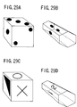
- a modification can be considered in which an image printed on each side of the die is altered or a shape of the die is altered from the cube shape into another shape, such as a pencil shape having a hexagonal cross section and 6 different images on the six sides thereof respectively (such as that shown in FIGS.29B and 29D). If such a modification is performed on the die and the game apparatus should respond to the modification, it is necessary to substantially modify software programs for recognizing the images of the die, and thus costs for the modification are substantially large.
- the above-mentioned apparatuses are not very adaptive for a modification of a die such as altering an image on each side of the die. Further, in such a rolled number determining method as described above, an appropriate pattern recognition may be disturbed due to some stains on a surface of a die, a camera lens, a light or the like.
- Japanese Laid-Open Patent Application Nos.1-259888, 2-249574, and 2-249575 disclose game apparatuses.
- a rolled number of a die is not determined in a manner such as that mentioned above.
- a method such as that in which a magnet is embedded in the die, it is possible to know a rolled number of a die before the die is thrown.
- unexpectedness inherently included in a die game may be reduced and thus a player may lose interest in the game.
- each side of a die has converting means and a tag embedded therein.
- the converting means converts an identification number of a respective die number into an electromagnetic signal.
- the tag has a coil which emits the converted electromagnetic signal.
- a receiving coil provided in a surface on which the die is rolled receives the emitted electromagnetic signal.
- a respective tag provided in each side of a die has the above-mentioned converting means and electromagnetic-signal emitting coil and, in addition, has a power storing capacitor and storing means for storing a respective die number. Therefore, a construction of each tag is complicated and it is thus difficult to miniaturize, to reduce a weight of, and to reduce costs of the tag.
- the present invention has been made so as to solve the above-mentioned problems, and an object of the present invention is to provide an apparatus for determining a part of an object.
- this apparatus it is possible, with a relatively simple method, to instantaneously, surely determine a part of an object. Further, a determination mechanism is not exposed to players, and the determination is possible even if an object is somewhat inclined or stains are present on a surface of the object.
- An apparatus for determining a part of an object, comprises: an object having a plurality of parts, wherein each part of said plurality of parts can face a predetermined direction; a plurality of resonant circuits, mounted in different predetermined positions of said object, and having different resonance frequencies; sending means for sending signals having a plurality of frequencies corresponding to said resonance frequencies of said plurality of resonant circuits; and detecting means for detecting resonance signals of said plurality of resonant circuits.
- each resonant circuit resonates with its own resonance frequency in response to a signal having a frequency component corresponding to the resonance frequency of the resonant circuit.
- the resonant circuit sends a signal of the resonance frequency.
- the thus-sent signal is detected by the detecting means.
- the signal sent from the sending means attenuates due to a relevant propagation distance. Therefore, a resonant circuit located relatively near to the sending means can receive the signal at a relatively high signal level.
- the signal sent from the resonant circuit as a result of the resonance also attenuates due to a relevant propagation distance. Therefore, the signal sent from a resonant circuit located relatively near to the detecting means can be received by the detecting means at a relatively high signal level.
- the signals sent from the sending means are used in the resonance in the resonant circuits, and are thus sent from the resonant circuits, the thus-sent signals being then received by the detecting means.
- These signals have frequency components corresponding to the resonance frequencies of the resonant circuits, and each of levels of the frequency components is different due to the direction along which the object faces.
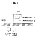
- FIG.1 shows a principle of the present invention.
- a die D is placed on a plate P, and two resonant circuits R1, R2 having different resonance frequencies f1, f2 are embedded at opposite positions in the die D.
- the die D is placed on the plate P in a position in which the resonant circuit R1 is located at a top position and the resonant circuit R2 is located at a bottom position by chance.
- Sending means T and detecting means S are provided below the plate P.
- a signal having frequency components of the frequencies f1 and f2 is sent from the sending means T upward.
- the signal is received by the resonant circuits R1 and R2 which then start resonating with their own resonance frequencies f1 and f2 respectively.
- the bottom resonant circuit R2 is located nearer to the sending means T than the top resonant circuit R1, and thus receives the signal from the sending means T at a relatively high level. As a result, the bottom resonant circuit R2 resonates at a relatively high level.
- the resonating resonant circuits R1 and R2 send signals of the frequencies f1 and f2 with levels corresponding to the resonance levels respectively.
- the level of the signal sent from the bottom resonant circuit R2 is relatively high in comparison to the level of the signal sent from the top resonant circuit R1.
- the sent signals are received by the detecting means S.
- the bottom resonant circuit R2 is located near to the detecting means S. Therefore, the signal sent from the bottom resonant circuit R2 is received by the detecting means S at a relatively high level in comparison to the signal sent from the top resonant circuit R1.
- the bottom resonant circuit R2 receives the signal sent from the sending means T at the relatively high level and further the signal sent from this resonant circuit R2 is received by the detecting means at a relatively high level.
- the level of the signal sent from the bottom resonant circuit R2 and then received by the detecting means S is a higher level. Therefore, when analyzing frequency components of the signals received by the detecting means S, a level of the frequency component of the frequency f2 of the bottom resonant circuit R2 is higher than a level of the frequency component of the frequency f1 of the top resonant circuit R1.
- a phenomenon inverse of that described above occurs.
- a level of the frequency component of the frequency f1 of the bottom resonant circuit R1 is higher than a level of the frequency component of the frequency f2 of the top resonant circuit R2.
- each of levels of frequency components of the resonance frequencies included in the signals received by the detecting means S is different due to a direction along which the die D faces. Using this phenomenon, it is possible to determine along which direction the die faces.
- the apparatus further comprises; a plate having therein said sending means and detecting means; and determining means for determining a part of said object placed on said plate, said part facing said predetermined direction, using differences of detected levels of said resonance signals of said plurality of resonant circuits of said object detected by said detecting means.
- the apparatus By using the apparatus, it is possible to immediately and surely determine a direction along which the object faces with a relatively simple system. Further, by selecting the resonance frequencies within a predetermined range, it is possible to make the relevant signals easily transmitted by the object and to make the plate on which the object moves of common materials. As a result, it is possible to embed the resonant circuits in the object and also to provide the sending means and detecting means below the plate. Thus, it is possible to prevent such a determining mechanism from being exposed to players. Further, even if stains are present on a surface of the object or the object is somewhat inclined, the determination is possible.
- the apparatus further comprises control means for controlling said sending means and detecting means; wherein: said control means controls said sending means so that said sending means, sends, one at a time, signals having frequencies equal to said plurality of resonance frequencies of said plurality of resonant circuits, in a manner in which the signal of a resonance frequency is sent, sending is stopped for a predetermined time, and th n the signal of a subsequent resonance frequency is sent; and said control means controls said detecting means so that, during a time in which said sending means stops sending the signal, said detecting means detects a reverberation oscillation of said plurality of resonant circuits which is caused by the signal sent immediately before, and compares a phase of the detected reverberation oscillation with a phase of said signal sent immediately before.
- said control means controls said sending means so that said sending means, sends, one at a time, signals having frequencies equal to said plurality of resonance frequencies of said plurality of resonant circuits, in a manner in which the signal of a resonance
- a respective signal sent from each of the resonant circuits is, one at a time, surely, analyzed.
- the sent signal can be effectively separated from the received signal and, thus, certain phase comparison can be performed.
- said sending means includes an antenna comprising an electric wire forming at least one loop, and a formation of said antenna and said plurality of resonant circuits is such that each of said resonance frequencies of said resonant circuits is sufficiently low in comparison to a resonance frequency of said antenna and, as a result, a wavelength corresponding to said resonance frequency of said antenna is so short that said wavelength may be neglected in comparison to wavelengths corresponding to said resonance frequencies of said resonant circuits.
- the antenna is prevented from oscillating itself with the resonance frequencies. Therefore, it is possible to improve a S/N ratio of signals received by the antenna, thus surely measure signal levels of the received signals, and thus surely identify a resonant circuit located at a specific position.
- An object according to the present invention a part of which can be automatically determined, comprises: a plurality of parts, wherein each part of said plurality of parts can face a predetermined direction; and a plurality of resonant circuits, mounted in different predetermined positions of said object, and having different resonance frequencies.
- said object comprises a polyhedron and a respective one of said plurality of parts corresponds to each side of said polyhedron.
- said plurality of parts can be visually identified by different numbers provided on said plurality of parts. As a result, players may identify each part of the object visually, clearly in a play.
- a respective one of said resonant circuits is provided in each of said sides of said polyhedron.
- said object comprises a plurality of objects.
- said object number by using a combination of object numbers of the plurality of objects as an object number, it is possible to increase the number of object numbers, and thus it is possible to increase player's interests on a relevant game.
- each of said resonant circuits comprises a tank circuit comprising a coil and a capacitor, said plurality of resonance frequencies being different as a result of capacitances of the capacitors being different.
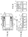
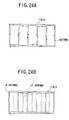
- FIGS.2A, 2B and 2C A general construction of a dice game machine in a first embodiment using an apparatus for determining a part of an object according to the present invention will now be described with reference to FIGS.2A, 2B and 2C.
- FIG.2A shows a plan view of the dice game machine 10 using the present invention
- FIG.2B shows a side elevational view thereof
- FIG.2C shows a front view thereof.
- the dice game machine 10 is a game machine such as that placed in an amusement facility such as a game center.
- the machine 10 includes a body 12, a screen unit 14 standing at the rear of the body 12, and a light unit 16 forward extending from the screen unit 14.
- the body 12 is provided with a total of eight satellites (game stations) 18, four at the left and four at the right, so a plurality of players may simultaneously play a game.
- Each satellite is provided with various operation switches, a display device, and so forth necessary for playing a game.
- the screen unit 14 is provided with a display 20 which may display how a game is going on, rules of the game and so forth.
- a dot display unit 21 is provided above the display 20 for displaying a rolled number of a die.
- the light unit 16 horizontally extends from the top of the screen unit 14, lights the body 12 and satellites 18 from the top and thus enhances an ornamental effect.
- a center part of the body 12 sandwiched by the left and right satellites 18 is covered by a transparent dome 22.
- a field 24 having a wide level plane for the die to roll thereon.
- a surface of the field 24 is provided with, for example, a green felt sheet stuck thereon.
- a general playing method of the game machine 10 will now be described.
- a general game flow is that each of a plurality of players guesses a rolled number of the die; one of the players throws the die through a device, referred to as a shooter; and a game result for each player is determined based on a resulting actual rolled number of the die.
- each player stands (or sits down) in front of a respective one of the satellites 18. Then, each player inputs his or her intention to participate in a game to the machine 10 and thus the machine 10 gives guidance of the game by supplying a predetermined display on the display device of a respective one of the satellites 18. Then, each player follows the guidance, such as guessing rolled numbers of two dice, and inputs the guessed rolled numbers of the dice into the machine 10.
- the dice game machine 10 then automatically selects one satellite from among the satellites 18, which are engaged by the plurality of players. Thus, one player is selected from among the plurality of players to be the shooter. In this game, in order to providing fairness, this selection is performed using a method such as, for example, a random number calculation or the like. As a result of the selection operation, the dice game machine 10 lights a lamp of a shooting button 26 of the selected satellite and thus urges the relevant player to hit the shooting button 26.
- the shooting button 26 is a lighting button which is provided with the lamp therein and each satellite is provided with a relevant one thereof.
- the thus-selected shooter hits the relevant shooting button 26 with his or her hand.
- the two dice (not shown in the figures) which were previously set in a shooting mechanism provided at the right end in FIG.2B of the field 24 are shot by the shooting mechanism from a front side of the field (a reverse side of the screen unit 14).
- Acceleration given to the two dice in the shooting operation by the shooting mechanism varies depending on an intensity with which the shooter (selected player) hits the shooting button 26. Specifically, when the shooter hits the button 26 strongly, the dice are shot strongly. When hit weakly, the dice are shot weakly. Thus, the shooter may adjust the hitting intensity in an attempt to have his or her mind so that his or her guessed rolled numbers of the dice be actually rolled.
- a hitting intensity detecting mechanism is provided.
- a projection is provided at the bottom surface of the shooting button 26 and a force receiving unit is provided below the projection.
- the projection hits the force receiving unit.
- a well-known piezoelectric device may be used in the force receiving unit which is used to convert a hitting intensity applied to the shooting button 26 into an electric signal when the shooting button 26 is hit by the shooter.
- a hitting intensity is determined by the dice game machine 10.
- the thus-shot two dice roll on the field due to the given acceleration, and then naturally stop.
- a number of a side facing upward of each die which has thus stopped is referred to as a 'rolled number' of the die.
- the field 24 on which the dice thus roll is located at a position at which each player standing in front of a relevant satellite can directly look via the transparent dome 22, as shown in FIG.2A.
- each player can in real time recognize an operation of the dice and resulting actual rolled numbers thereof.
- the dice game machine 10 is provided with a rolled number determining system for instantaneously determining an actual die rolled number.
- An apparatus for determining a part of an object according to the present invention is applied to this rolled number determining system.
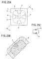
- the rolled number determining system when a movement of a die 1 (see FIG.25A) stops, the rolled number determining system can determining a current rolled number of the stopped die 1 approximately at the same time each player visually recognizes the current rolled number of the stopped die 1.
- the rolled number determining system will now be described in general.
- the system includes a combination of a plurality of transponders 4 (see FIG.25A) embedded in the die and an antenna 24a (see FIGS.17 and 26B) laying beneath a felt sheet 24c of the field 24.
- the antenna 24a is included in a detecting unit 220 connected to a field control unit 200 shown in FIG.3A.
- the detecting unit 220 has, in addition to the antenna 24a, a control unit 221, a sending unit 222, and an analyzing unit 223 (see FIG.17). Either the sending unit 222 or analyzing unit 223 is connected to the antenna 24a and the control unit 221 is connected to a main control CPU 210 in the field control unit 200 via an input/output control I/F (see FIGS.3 and 17).
- Each of the plurality of transponders is formed of a resonant circuit in the apparatus for determining a part of an object according to the present invention.
- the antenna 24a and the sending unit 222 act as sending means in the apparatus for determining a part of an object according to the present invention.
- the antenna 24a and analyzing unit 223 act as detecting means in the apparatus for determining a part of an object according to the present invention.
- the control unit 221 acts as determining means in the apparatus for determining a part of an object according to the present invention.
- the sending unit 22 emits predetermined electromagnetic waves via the antenna 24a.
- An electromagnetic wave of a specific resonance frequency then send by a transponder (tag) which is located at a position nearest to the antenna 24a is then received by the antenna 24a.
- a die number corresponding to this transponder is determined.
- a transponder representing a die number relevant to the side is embedded.
- a different resonance frequency is assigned to each transponder.
- a transponder which is embedded in a side (bottom side) sends a signal of a frequency relevant to a die number of an opposite side (top side).
- a thus-sent electromagnetic wave is received by the antenna 24a and analyzed by the analyzing unit 223.
- the relevant die number is determined as a relevant rolled number of the die.
- the dice game machine 10 uses the two dice. Therefore twelve transponders having different resonance frequencies representing each side of each of the two dice are necessary to be provided. Six of the twelve transponders are embedded in six sides of one die, respectively, and six thereof are embedded in six sides of the other die, respectively. Actually, not only a relevant transponder but also the other transponders send electromagnetic waves of the their own resonance frequencies. However, by providing the antenna 24a having a construction such that the relevant transponder which is one embedded in the bottom side of the die is received by the antenna with an especially high level, a relevant die number can be determined as a relevant rolled number.
- Each of the transponders is formed of a tank circuit of a parallel circuit of a coil and a variable-capacity capacitor for forming a resonant circuit.
- a variable-capacity capacitor for forming a resonant circuit.
- the analyzing unit 223 analyzes electromagnetic waves sent from the transponders in response to the electromagnetic waves sent from the antenna 24a.
- Frequencies which are obtained as a result of the analyzing are those of two transponders which are embedded in the bottom sides of the two dice.
- the frequencies represent dice numbers of the opposite sides, that is, the top sides. Consequently, the dice numbers represented by the obtained frequencies are the rolled numbers of the dice.
- the dice game machine 10 uses the above-described rolled number determining system, a simple and accurate rolled number determination can be realized, in comparison to conventional methods in which image recognition is performed for recognizing rolled numbers. Further, it is possible to inexpensively provide a rolled number determining system.
- the dice game machine 10 after thus determining rolled numbers of the dice, compares the thus-determined numbers with guessed rolled numbers which were previously input.
- the machine 10 determines a game result for each player based on a result of the comparison, agreement or disagreement. Further, based on determined game results, the machine 10 automatically performs point allotment calculation and so forth depending on points which were previously set by each player.
- the dice game machine 10 After a first game operation has been thus finished, the dice game machine 10 then automatically collects the two dice on the field 24 through a collecting mechanism to the above-mentioned shooting mechanism, thus preparing for a subsequent game operation.
- a time required for the dice collection is approximately 25 to 30 seconds and, during the time, each player inputs a rolled number guess for the subsequent game operation and so forth.
- the dice game machine 10 selects a subsequent shooter (one of the players) and lights a shooting button 26 of a relevant satellite, thus urging the shooter to hit the button. Thus, a similar game operation is repeated.
- Such shooter selection may be performed in a manner in which the shooter is shifted to a next player sequentially from the first selected player, and thus a relevant instruction display is performed on a relevant satellite.
- a selection method is not limited to this manner. For example, it is also possible to select as a subsequent shooter the player who gained the highest number of points allotted in the preceding game operation.
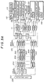
- FIG.3A shows a block diagram of the inside and periphery of a main control unit 100 and the above-mentioned field control unit 200.
- FIG.3B shows a block diagram of the inside and periphery of a satellite control unit 300 of eight satellite control units 300 having identical formations.
- the control system includes the main control unit 100, field control unit 200 and control units 300 provided for eight satellites 18 respectively. These control units are formed on a main control substrate, a field control substrate, and satellite control substrates, respectively.
- the main control unit 100 has two main CPUs (Central Processing Units) 110 and 130 cooperatively, generally controlling operations of the main control unit 100. These main CPUs are connected with each other.
- the main CPU 130 is connected to a main control CPU 210 of the field control unit 200 via an optical communications unit including an optical cable and communications control IC (Integrated Circuit) I/Fs provided at two ends of the optical cable.
- the main CPU 130 is connected to a sub-CPU 320 of each satellite control unit 300 via an optical communications unit similar to the above-mentioned one (see FIG.3A).
- the main CPU 130 is connected to an indicating unit 131 and a display unit 132 via input/output control IC I/Fs, respectively.
- the main CPU 110 is connected to a motor driving unit 112 and the shooting mechanism 114 via an input/output control IC I/F. Further, the motor driving unit 112 is connected with the collecting mechanism 13. Further, the main CPU 110 is connected to a clock IC 111, to an illumination unit 115 via an input/output control IC I/F, and to an operation unit 116 and an illumination unit 117 via an input/output control IC I/F. Further, the main CPU 110 is connected to a CRT (Cathode Ray Tube) 119 via a video IC 118. Further, the main CPU 110 is connected to a printer 120 and an audio unit 121 via input/output control IC I/Fs. In the above-mentioned connections, connections of the illumination units 115, 117, and display unit 132 with relevant input/output control IC I/Fs are made via optical communications units similar to the above-mentioned one.
- the field control unit 200 has a main control CPU 210 for generally controlling the control unit 200.
- the main control CPU 210 is connected to the sub-CPU 320 of each satellite control unit 300 via an optical communications unit similar to the above mentioned one. Further, the main control CPU 210 is connected to the above-mentioned detecting unit 220 via an optical communications unit similar to the above mentioned one.
- Each one of the satellite control units 300 has a main CPU 310, two sub-control CPUs 320 and 330 for cooperatively, generally controlling the respective control unit 300.
- the two sub-CPUs 320 and 330 are connected to each other and also connected to the main CPU 310 via an input/output control IC I/F.
- the sub-CPU 320 is further connected to the shooting button 26 via an A/D converter 323. Further, the other sub-CPU 330 is connected to an LCD (Liquid Crystal Display device) 331.
- the main CPU 310 is connected to an indicating unit 340 via an optical communications unit similar to the above-mentioned one, and the indicating unit 340 is connected to an LED (Light-Emitting Diode) 341 and a lamp 342 via an input/output control IC I/F.
- LED Light-Emitting Diode
- optical communications units are used appropriately so that signal transmissions between relevant units may be made high speed.
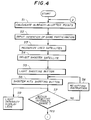
- FIGS.4 and 5 shows a flowchart of a main operation of the dice game machine 10.
- the main CPU 130 of the main control unit 100 uses the display unit 132, which itself also has a CPU for performing video control, and thus appropriately displays, through the display 20 shown in FIG.2A, general information such as rules, progress and so forth of a game.
- the main CPU 110 uses the two illumination units 115 and 117 and thus produces illuminations provided in the light unit 16 shown in FIG.2A in accordance with a predetermined program.
- various audio signals, music and so forth are output in accordance with a predetermined program through the audio unit 121 using MIDI (Musical Instrument Digital Interface).
- MIDI Musical Instrument Digital Interface
- the operation unit 116, CRT 119 and printer 120 connected to the main control unit 100 are used mainly for a maintenance work for the dice game machine 10. For example, servicemen use them for checking how the machine has been used.
- each player inputs his or her intention of participating in a relevant game.
- a relevant one of the satellite control units 300 transmits the relevant information to the main CPU 130 in the main control unit 100 via a relevant one of the sub-CPUs 320.
- the CPU 130 recognizes with which satellite 18 a player is engaged in S3.
- the indicating unit 310 of each satellite 18 is provided with a numeral indicating device for indicating already-allotted points and set points with a combination of LEDs, and indicates the player's already-allotted points and set points.
- the sub-CPU 320 determines already-allotted points for a relevant player and indicates a guidance in the LCD via the sub-CPU 330 for the player to set points. In response to this, the player sets points for the play by pressing setting buttons provided on the satellite. Then, thus-input setting information is transferred to the main CPU 310 which then indicates the set points on the above-mentioned numeral display device of the indicating unit 340. Further, when a preceding play of the game has been finished and point allotment therefor has been finished, the main CPU 310 calculates a resulting already-allotted points for each satellite in S1. The main CPU 310 determines for each satellite that a player is engaged with the satellite as long as relevant allotted points have not yet become zero.
- Each one of the sub-CPUs 330 indicates on the relevant LCD 331 information of game progress and gives a guidance for the play of the game for the relevant player. Then, according to a predetermined program, the main CPU 130 of the main control unit 100 selects a satellite as a shooter in S4. The main CPU 130 then transfers relevant information to the satellite control unit 300 of a thus-selected satellite. In response to this, the sub-CPU 320 of the satellite control unit 300 having received the transferred information transfers, via the main CPU 310, information for instructing the indicating unit 340 to light the lamp 3432 provided inside the shooting button 26. As a result, the indicating unit 340 lights the lamp 342 in the shooting button 26 in S5.
- the shooter hits the shooting button 26 in S6, and thus the above-mentioned hitting-intensity detecting mechanism converts the hitting intensity into an electric signal which is then transferred to the A/D converter 323.
- the A/D converter 323 converts the electric signal into a digital signal and sends it to the main CPU 310.
- the main CPU 310 according the digital signal, lights a number of LEDs, depending on the hitting intensity, of hitting intensity display LEDs provided around the shooting button 26, in S9.
- the main and sub-CPU 310 and 320 function so that a signal generated from a voltage signal generating unit 60 of each of the shooting buttons of the other satellites is invalidated.
- relevant ones of the hitting intensity display LEDs may not be lit and also the shooting mechanism may not operate in response to this erroneous hitting.
- FIG.6 shows an arrangement of the hitting intensity display LEDs provided around the shooting button 26 of each satellite 18. As shown in the figure, the plurality of LEDs are arranged along radial directions, Approximately immediately after the shooting button 26 is hit by the shooter, a number of LEDs depending on the hitting intensity are lit. Therefore, the shooter can recognize the hitting intensity immediately after the hitting and thus it is possible to increase the player's interest in the game.
- the shooting mechanism does not shoot the dice. This is because if the shooting mechanism gives to the dice a very small acceleration, the dice may not be appropriately shot, and may roll slightly and then stop soon. If such an operation is possible, the shooter may control rolled numbers of the dice. As a result, players' interest for the game may be decreased.
- an appropriate program is set to the main CPU 110 of the main control unit 100 shown in FIG.3A for controlling the shooting mechanism 114 such that an operation of the shooting mechanism 114 giving such a very small acceleration to the dice is inhibited.
- an intensity in hitting the shooting button 26 should be within the effective intensity range and thus the dice may be shot with an appropriate acceleration.
- the hitting intensity display LEDs shown in FIG.6 are advantageous for appropriately using the shooting mechanism's function.
- a number of LEDs may be relevant to the effective intensity range. Specifically, one or zero of the LEDs is lit when the shooting button 26 has been hit with the lowest intensity of the effective intensity range. When the button 26 has been hit with the maximum intensity of the effective intensity range, all of the LEDs are lit. Thereby the shooter can visually recognize the effective intensity range and thus can control a hitting intensity to be within the effective intensity range. Thus, the shooter can easily control the hitting intensity.
- the LEDs shown in FIG.6 function as illuminations and are lit by the main CPU 310 according to a predetermined program.
- a program for controlling the shooting mechanism includes steps which will now be described.
- the dice game machine 10 indicates, in S8, on the LCD 331 of the relevant satellite, contents for instructing the shooter to again hit the shooting button 26 with a stronger intensity.
- the shooting mechanism is controlled so that the shooting mechanism automatically shoots the dice so as to give a predetermined acceleration to the dice. Thereby, it is prevented that other players wait for a long time and thus lose interest in the game.
- the shooting mechanism 114 When the shooter hits the shooting button 26, information indicating the hitting intensity is converted into a digital signal by the A/D converter 323. The digital signal is then transferred to the main CPU 130 of the main control unit 100 via the sub-CPU 320. This information is then transferred to the main CPU 110 which then controls the shooting mechanism 114 to shoot the dice with an intensity relevant to the shooter's hitting intensity. As a result, the shooting mechanism 114 shoots the dice and gives a relevant acceleration to the dice, in S10. The dice thus shot from the shooting mechanism 114 provided at the right end of the field 24 shown in FIG.2B then fly using the given acceleration above the field 24. Then, the dice fall on the field 24 either after colliding with a wall provided at the left end of the field 24 or directly. The dice may roll and then stop.
- the main control CPU 210 When the shooter hits the shooting button 26, relevant information is transferred to the main control CPU 210 of the field control unit 200 from the relevant satellite. In response to this, the main control CPU 210 causes the detecting unit 220 to operate.
- the detecting unit 220 uses the above-mentioned rolled number determining system, determines rolled numbers of the two stopped dice on the field 24, in S11. Information of the thus-determined rolled numbers of the dice is transmitted to the main CPU 130 of the main control unit 100 via the main control CPU 210 of the field control unit 200. Then, the transmitted information is transmitted to the indicating unit 131 having the dot display unit 21 shown in FIG.2C. Then, the determined rolled numbers are indicated on the dot display unit 21, in S13.
- the main CPUs 110 and 130 determine a game result for a player of each satellite according to the rolled number information, and perform point allotment according to the determined game result, in S12. Further the game results and point allotment are displayed on the display 20 through the display unit 132.
- the main control CPU 210 transmits relevant information of the finishing to the main CPU 110 of the main control unit 100.
- the main CPU 110 causes the collecting mechanism 112 to operate and thus collects the two dice on the field 24 and returns them to the shooting mechanism automatically, in S14.
- the main CPU 110 indicates a guidance for the subsequent play of the game on the display 20 via the display unit 132 and further on the LCD 331 via the sub-CPUs 320, 330 of each satellite control unit 300. Then, the dice game machine 10 starts calculation of already-allotted points for each satellite, repeats the above-mentioned operations, and thus proceeds with the game playing.
- the numbers and functions of the main and sub-CPUs 110, 130, 210, 310, 320, and 330 are not limited to those mentioned above, and may be freely altered as long as the above-mentioned functions of the dice game machine 10 are generally performed. However, it is preferable that those matters are determined with consideration of a data processing capability of each CPU, functions of peripheral units connected to the CPU, and so forth. Thus, it should be prevented that a smooth progress of the game is disturbed by a time required for executing each step by the CPU, a time required for transmitting a signal between CPUs and so forth.
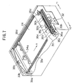
- FIG.7 simply shows a perspective view of the inside of the body 12 of the dice game machine 10 shown in FIGS.2A, 2B and 2C.
- the above-mentioned shooting mechanism 114 and the collecting mechanism 113 are provided around the field 24.
- the front part of the field 24 is connected to an inclined portion 30, and the dice shot on the field 24 are moved by the collecting mechanism 113 to the inclined portion 30.
- the two dice which have reached the inclined portion 30 slide down on the inclined portion 30, and then are collected by the collecting mechanism 113 to the center.
- a shooting plate of the shooting mechanism 114 is positioned. Therefore, the two center-collected dice are placed on the shooting plate.
- FIG.7 shows a state in which the shooting mechanism 114 is removed.
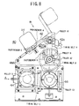
- the shooting mechanism 114 (see FIGS.8 and 9) is normally mounted in a space 32 shown in FIG.7.
- FIG.8 shows a side elevational view
- FIG.9 shows a front view of the shooting mechanism 114
- FIG.10 shows a partial view viewed along an arrow B shown in FIG.8,
- FIG.11 shows a partial view viewed along an arrow A shown in FIG.8.
- the shooting mechanism 114 is a unit type, and the entirety thereof can be drawn out from the body 12 of the dice game machine 10. Accordingly, maintenance and repairing thereof may be easily performed.
- the shooting mechanism 114 includes the above-mentioned shooting plate 42, a driving AC motor 44, an electromagnetic powder clutch 46 for adjusting power transmission for the AC motor 44, and pulleys and timing belts as power transmission mechanisms for these components.
- the AC motor 44 and electromagnetic powder clutch 46 are mounted on a side plate 48A. As shown in FIG.11, a pulley D is mounted on a driving shaft of the AC motor 44. Further, a pulley C2 is mounted on a power input side of the electromagnetic powder clutch 46 and a pulley C1 is mounted on a power output side thereof. A timing belt C links the pulley D of the AC motor 44 with the pulley C2 of the electromagnetic powder clutch 46.
- a shaft 50 is rotatably supported between the side plate 48A and another side plate 48B.
- the shaft 50 has a pulley B and a pulley A2 mounted thereon.
- the pulley B is positioned vertically above the pulley C1 of the power output side of the electromagnetic power clutch.
- These pulleys are linked by a timing belt C.
- the diameter of the pulley B is larger than the diameter of the pulley C1 and thus a predetermined speed reduction ratio can be obtained thereby.
- a tension of the timing belt is adjusted as a result of either the AC motor 44 or the electromagnetic powder clutch 46 moving slightly.
- a shaft 52 is rotatably supported between the side plate 48A and the other plate 48B, similarly to the shaft 50.
- a pulley A1 is mounted on the shaft 52, and a timing belt A links the pulley A1 with the pulley A2 of the shaft 50.
- a tension of the timing belt A can be adjusted as a result of pressing a part between the pulley A1 and pulley A2 with an idle roller 54. Accordingly, it is necessary to provide an adjusting mechanism such as an idle pulley for adjusting the tension of the timing belt A. As a result, assembly can be easily performed and also it is possible to reduce a number of components.
- the shooting plate 42 is, ordinarily, in an inclined state shown in FIG.8 by a solid line, and this state is determined using a photosensor A.
- This photosensor A is one of a type having a rotating lever, and, as a result of the lever being rotated and thus moved to a predetermined position as a result of the lever touching a part of the shooting plate 42, a light path is blocked and the photosensor outputs a relevant signal. As shown in FIG.8, the photosensor A is provided at the bottom side of the shooting plate 42.
- a width W of the shooting plate 42 is approximately equal to a width of two dice and two dice can be shot at the same time.
- two openings 42b are provided at positions at which the dice are placed and a photo sensor C is provided for each of the openings 42b.
- the photo sensor C is of the same type as the photosensor A, and is mounted so that an end of a rotating lever projects through the opening 42b when the shooting plate 42 is at a home position (shown in FIG.9 by the solid line). Therefore, when a die is moved to the predetermined position of the shooting plate, the rotating lever is pressed by the die, and thus is rotated. Thus, whether or not each of the dice is positioned at the shooting position can be determined.
- An extending portion 42c is provided at an extending end of the angular-C-shaped portion 42a.
- the extending portion 42c is in a state in which the extending portion 42c enters a slit of a photosensor B of a photo interrupter mounted on the side plate 48A. Thereby, it can be determined that the shooting plate 42 has completed a shooting operation, that is, is at an end position.
- pulleys have teeth thereon and timing belts having waves thereon. Therefore, there is no possible problem due to a back rush occurring when using gears, and highly responsive power transmission mechanisms can be provided.
- the two photosensors C are provided because the two dice are used.
- the number of the photosensors C may be appropriately altered according to alteration of the number of the dice.
- electric micro limit switches or the like may be used instead of using the photosensors.
- the above-described shooting mechanism 114 is contained in the space 32 shown in FIG.7. After being contained, when the above-described shooting plate 42 is at the home position, the shooting plate 42 is coincident with an opening 30a of the inclined portion 30. Accordingly, the dice, after sliding on the field 24 and the inclined portion 30, can be move to positions on the shooting plate 42.
- the two dice are on the field 24 and are moved to the predetermined position (shown by a solid line in FIG.8) on the shooting plate 42 by the collecting mechanism which will be described later.
- the collecting mechanism which will be described later.
- each player of the dice game machine 10 guesses rolled numbers of the dice, sets and thus inputs to the dice game machine 10 points for the guessed rolled numbers.
- the main CPUs 110 and 130 of the main control unit 100 provided in the body 12 specify a satellite as a subsequent shooter.
- the shooting plate 42 it is determined in S32 whether or not the shooting plate 42 is at the home position. If the shooting plate 42 is not at the home position, the AC motor 44 is rotated along a direction reverse of that when shooting, and thus the shooting plate 42 is returned to the home position in S34. Then, in S32, when it is determined that the shooting plate 42 is at the home position, the AC motor 44 is rotated along a shooting direction and runs at a predetermined speed in S36. At this time, a predetermined slight electric current is supplied to the electromagnetic powder clutch 46 in S38. With this electric current, the electromagnetic powder clutch 46 is not in a torque transmission state. Therefore, in this state, the pulley C2 at the power input side of the electromagnetic powder clutch 46 is rotated via the timing belt C, while the pulley C1 at the power output side is not rotated.
- the shooting button 26 is linked to the voltage signal generating device 60 including the piezoelectric device or the like, and a voltage signal in proportion to the shooter's hitting intensity is output therefrom.
- a rubber cushion (not shown in the figure) is provided for the shooting button 26 such that shooter's hitting shock may not be directly transmitted to a panel on which the shooting button 26 is mounted.
- a pressing portion 68 is provided at the bottom of the shooting button 26, and when shock is applied to the shooting button, the shock is transmitted to the voltage signal generating unit 60 via the pressing portion 68 which then outputs the voltage signal according to the shock.
- This voltage signal is processed by the CPUs 310 and 320 of the satellite control unit 300, and converted into a digital signal which may have 128 grade levels.
- a voltage is applied to the electromagnetic powder clutch 46 in S46.
- Such a process for converting the voltage signal into the digital signal and applying of the relevant voltage may be performed using well-known circuits. Therefore, a description thereof will be omitted.
- the shooting button 26 has a lamp inside thereof, and by lighting the lamp, a satellite of a shooter is indicated. In other words, a lit one of the shooting button 26 is one which can be used for shooting the dice.
- the electromagnetic powder clutch 46 transmits a torque according to the electric current. That is, when the hitting power is weak, a sufficient exiting current is not supplied to the electromagnetic powder clutch 46. Therefore, the clutch 46 transmits a torque to the pulley C1 while sliding. By the torque transmitted to the pulley C1, the shaft 52 is rotated via the timing belts A and B, and the shooting plate 42 fixed on an end of the shaft 52 is rotated accordingly. As a result, the dice are shot toward the field 24. Accordingly, a shooting power of the dice is controlled by an electric current supplied to the electromagnetic powder clutch 46.
- the shooting plate 42 is rotated and it is determined in S48 whether or not the shooting plate 42 has reached the end position. If a predetermined time has elapsed without the shooting plate 42 having reached the end position since the rotation of the shooting plate 42 was started, S42 is executed. Then, an error signal is output. When it is determined that the shooting plate 42 has reached the end position, the AC motor 44 is rotated along the reverse direction and thus the shooting plate 42 is returned to the home position in S50, and thus the shooting operation is finished.
- the shooting mechanism 114 By using such a construction of the shooting mechanism 114, a time required from the shooter's hitting to the start of an actual dice shooting operation can be greatly reduced. Further, the shooting power can be controlled as a result of controlling button hitting power. Accordingly, the shooter can feel in control as if the shooter actually threw the dice with his or her hand.
- a shooting method applied in the present invention is not limited to the above-described method using the shooting button 26 and shooting mechanism 114. Any other method using determining means for numerically determining a manner in which a human being performs an operation such as a hitting operation, and driving means for giving an acceleration to a die according to a thus-determined numeral value can be applied.
- each of the passing determining units includes a light-emitting device and a photosensor disposed with a predetermined space.
- light beams emitted by the light-emitting device reach the photosensor, and when something passes therebetween the light beams are blocked and thus passing is determined.
- the shooter passes his or her hand through the two sets of passing determining units successively. By measuring a time between the hand passing one of the two passing determining unit and the hand passing the other, a speed of the hand passing the two passing determining units can be determined.
- the driving means uses the thus-determined speed for determining an acceleration which is given to the die.
- a compressor instead of the mechanism using the electromagnetic powder clutch and shooting plate, another mechanism can be used.
- a compressor generates compressed air which is then used for blowing a die.
- an acceleration is given to the die.
- a pressure control valve in a pipe for leading the compressed air to the die and appropriately operating the pressure control valve, it is possible to control the acceleration to be given to the die according to the numeric value of the manner in which the shooter performs an operation such as a hitting operation.
- the collecting mechanism 113 will now be simply described.
- the dice on the field 24 are pushed by a collect bracket 34a as a result of the collect bracket 34a moving along an X direction in the figure.
- the dice slide along the X direction and thus are carried to the inclined portion 30.
- a stopper 30b is provided at an X-direction end of the inclined portion 30, and projects obliquely vertically from the inclined portion 30 as a result of bending by a right angle.
- the two dice carried to the inclined portion 30 slide on the inclined portion 30 due to the inclination thereof. Then, the dice stop after come into contact with the stopper 30b.
- a collect lever 34b is provided on the collect bracket 34a and, thereby, even if the two dice have been vertically stacked, the top die is dropped to the field 24 and thus the stacked state is canceled.
- the collect bracket 34a is driven along the X direction as mentioned above by timing belts 33d and 33e fixed at two ends of the bracket 34a. These timing belts are driven via a pulley as a result of another timing belt 33b provided along directions Y1, Y2 in the figure being driven by a collect motor 33a. In order to ensure the function of this power transmission mechanism using the pulley, a pulley 33c is provided for applying an appropriate tension to the timing belt 33c.
- a fillip bar 36c moves along the Y1 direction.
- the top die is filliped and thus each of the two dice comes into contact with the stopper 30b.
- a respective one of timing belts 35b and 36b is driven along a respective one of the Y1 and Y2 directions.
- attract pads 35c and 35d provided at projecting ends of two attract bars respectively moye along the Y1 and Y2 directions respectively.
- the two dice are carried to the position of the opening 30a.
- the shooting plate 42 is provided at this position.
- the two dice are carried to the shooting plate 42.
- the collecting mechanism 113 by the functions of the collect bar 34b and fillip bar 36c, a stack state of two dice may be canceled. Therefore, the two dice are collected to the shooting plate 42 in a state in which the two dice are arranged along the Y1 and Y2 directions. As a result, it is possible to make a state of the dice identical for every shooting operation except for rolled numbers thereof. As a result, fairness of the game can be provided.
- an area of the field 24 is sufficiently wide.
- each player it should not be possible at all, at least prior to a shooting operation, for each player to precisely predict a detail of a movement of the dice in which the shot dice fly above the field 24, bounce off the above-mentioned wall, roll on the field 24, and then stop.
- the detail of the movement can be determined by each player immediately before the dice stop after the above-mentioned movement thereof.
- each player guesses rolled numbers of the dice by viewing positions (directions) of the dice each stage of the movement (being shot and then flying, bouncing off the wall, rolling on the field 24), and is glad and sad by turns.
- the above-mentioned shooting mechanism has a capability for enabling the above-mentioned movement of the dice.
- the dome 22 provided above the field 24 provides a sufficiently wide space therein such that the dice can fly at a certain height.
- each of the dice has a sufficiently large size such that each player standing in front of a relevant one of the satellites 18 can clearly determine a die number of each of the dice visually with his or her eyes.
- a change-over switch is operated so as to select a top terminal so that an AC electric current from an AC power source flows through an antenna formed of one electric wire. Then, if a tank circuit formed of a coil and a capacitor having a resonance frequency identical to a frequency of the AC power source is made to approach the antenna, this tank circuit starts a resonance phenomenon. If then the change-over switch is operated so as to select a bottom terminal and thus the flowing of the AC electric current through the antenna is stopped, the thus-started resonance phenomenon continues for a while due to a well-known characteristic of such a tank circuit. Such a phenomenon that a resonance oscillation continues without an external power supply is referred to as 'reverberation oscillation'. During this continuation of the reverberation oscillation, the tank circuit generates electromagnetic waves.
- the change-over switch is operated so as to select the bottom terminal and thus the antenna is connected to a detecting unit.
- the electromagnetic waves thus received by the antenna acting as an electric signal are supplied to the detecting unit.
- the detecting unit determines the presence of the tank circuit having the resonance frequency identical to the frequency of the above-mentioned AC power source, by determining that the electric signal is supplied to the detecting unit.
- FIG.15 generally illustrates an example of a method for applying the above-described technology to the rolled number determining system.
- a controller includes the above-mentioned AC power source, detecting unit and change-over switch.
- an antenna is provided beside a plate on which a die is placed and extends perpendicular to the plate.
- Six ID tags are embedded in the die and each thereof is located in proximity to the center of a relevant one of six sides of the die.
- Each of the ID tags is formed of the above-mentioned tank circuit and the resonance frequency thereof is different from that of each of the others.
- a plurality of tank circuits having resonance frequencies different from another acting as the ID tags are present around the antenna.
- it is necessary to identify a tank circuit which is embedded in a side of the die facing a specific direction for example, a tank circuit which is embedded in a side of the die facing upward or a side of the die facing downward.
- Electromagnetic waves mitted from the antenna cause a reverberation oscillation in each tank circuit, and electromagnetic waves resulting from the thus-caused reverberation oscillations are received by the antenna. It is considered that signal levels of the electromagnetic waves thus received by the antenna may be different from one another due to the above-mentioned difference of the spatial relationships. This difference of the received electromagnetic waves can be determined based on the frequency components thereof.
- the AC power source sends out through the antenna one electromagnetic wave at a time having a frequency equal to the resonance frequency of each tank circuit.
- signal levels of electromagnetic waves which are generated by the tank circuits due to resulting reverberation oscillations and then received by the antenna are measured for the frequency components corresponding to the resonance frequencies of the six tank circuits respectively.
- a tank circuit having a specific spatial relationship with the antenna may be identified.
- the AC power source supplying AC power to the antenna generates an electromagnetic wave having a frequency equal to a resonance frequency of each tank circuit.
- each difference between the frequencies to be generated is as small as possible.
- a difference between the resonance frequencies of the tank circuits is enlarged.
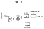
- FIG.16 shows a block diagram of an example of the detecting unit shown in FIG.14.
- This detecting unit uses a well-known superheterodyne system and thus measures a signal level of an electromagnetic wave received through the antenna for each frequency component.
- it is difficult to increase the 'Q' of each tank circuit.
- it is difficult to provide a tank circuit having a light weight, it is difficult to provide a tank circuit in which a continuation time of a reverberation oscillation is sufficiently long. Therefore, it is difficult to improve an S/N ratio when a signal level of a specific frequency component is measured, and thus it is difficult to measure a signal level of a specific frequency component with high accuracy.
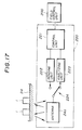
- FIG.17 generally shows a block diagram of the detecting unit 220 shown in FIG.3A, which uses this rolled number determining system.
- the detecting unit 220 includes the control unit 221, sending unit 222, analyzing unit 223 and antenna 24a, and, in addition, includes a change-over switch 224.
- the sending unit 222 responds to an electromagnetic wave sending out an instruction signal, and, through the antenna 24a, sends out electromagnetic waves, one at a time, having frequencies corresponding to resonance frequencies of the above-mentioned twelve transponders of the two dice 1.
- the analyzing unit 223 receives, via the antenna 24a, electromagnetic waves sent out from the transponder 4 of the dice, and supplies information of frequencies of the electromagnetic waves.
- the control unit 221 uses the thus-supplied information of the frequencies and then determines rolled numbers of the dice.
- the change-over switch 223 acts as the change-over switch shown in FIG.14, and changes connection of the antenna 24a.
- the antenna 24a can be appropriately used as a transmitting antenna and also as a receiving antenna.
- Information of twelve resonance frequencies of the transponders 4 of the dice 1 are previously stored in the control unit 221.
- the control unit 221 uses the information and causes the analyzing unit 223 to compare each of the twelve frequencies with a frequency of a received electromagnetic wave. As a result, two frequencies are obtained. Then, the control unit 221 obtains information of rolled numbers of dice 1 to which resonance frequencies corresponding to the thus-obtained two frequencies are previously assigned respectively. The thus-obtained rolled number information is sent to the field control unit 200.
- the dice 1 stop on the field 24 in a state in which a side of each of the dice 1 comes into contact with the field 24.
- a resonance frequency of one of the transponders 4 of a first die of the two dice 1 and a resonance frequency of one of the transponders 4 of a second die of the two dice 1 should be obtained.
- the rolled number information sent to the field control unit 200 from the control unit 221 as a result is information of a rolled number of the first die and a rolled number of the second die.
- the control unit 221 supplies an error signal to the field control unit 200, and in response to this, the CPU 210 of the field control unit 200 determines the game result to be an operation failure. This determination is then sent to the main control unit 100 which, as a result, causes the collecting mechanism 113 to collect the dice and send them to the shooting mechanism 114. Further, the main control unit 100, via the satellite control unit 300 of a satellite of a relevant shooter, urges the shooter to again hit the shooting button 26.
- FIG.18 shows further details of the detecting unit 220 shown in FIG.17.
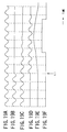
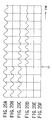
- FIGS.19A, 19B, 19C, 19D, 19E, 19F, 20A, 20B, 20C, 20D, 20E and 20F show signal waveforms in a circuit shown in FIG.18.
- the detecting unit 220 having the formation shown in FIG.18 extracts a frequency component having a phase coincident with a phase of an electromagnetic wave sent out from the antenna, which is a power source of reverberation oscillations, from among electromagnetic wave signals which are sent out from tank circuits as a result of the reverberation oscillations thereof and received through the antenna.
- the detecting unit 220 measures a signal level of the thus-extracted frequency component.
- a signal level at the antenna of the electromagnetic wave sent out from the tank circuit having the resonance frequency equal to the frequency of the electromagnetic wave signal sent out from the antenna is measured.
- the control unit 221 acting as a CPU controls a frequency synthesizer 222a which generates electromagnetic wave signals, one at a time, having a plurality of frequencies equal to the resonance frequencies of the twelve transponders 4 (tank circuits) of the two dice 1, as a result of selecting one of them sequentially.
- the frequency synthesizer 222 includes a well-known PLL circuit having a VCO (Voltage Controlled Oscillator).
- VCO Voltage Controlled Oscillator
- the thus-generated electromagnetic signals are supplied to a driver A 222b and a driver B 222c. Operations of the two drivers are controlled by the control unit 221, and are made to be ON/OFF in a timing which will now be described.
- the two drivers are alternately activated and a time interval of a fixed time is present between times of activations of the two drivers.
- the driver A is activated, and then after a predetermined time has elapsed, the driver A is deactivated. Then, after a predetermined time has elapsed, the driver B is activated and then after a predetermined time has elapsed, the driver B is deactivated. Further after a predetermined time has elapsed, the driver A is activated.
- the above-described operation is one cycle of operation. The cycle of operation is repeated each time a frequency generated by the frequency synthesizer 222a is changed.
- the drivers which thus have an electromagnetic signal supplied thereto then send out a corresponding electromagnetic wave through an antenna A and an antenna B.
- elements of the antennas A and B are alternately disposed in a rectangular detection area, and thus dead zones which may have otherwise appeared between antenna elements are canceled.
- FIGS.19A and 20A A waveform of one of the electromagnetic wave signals which are generated one at a time by the frequency synthesizer 222a, that is, a waveform of a signal at a point A in a circuit shown in FIG.18 is shown in FIGS.19A and 20A. Further, a waveform of an electromagnetic signal supplied to the antenna A or antenna B, that is, a waveform of a signal at a point B in the circuit shown in FIG.18 is shown in FIGS.19B and 20B. Because operation timings of the drivers A and B are controlled by the control unit 221 as mentioned above, the supply of the electromagnetic wave signal to the antenna A or antenna B is stopped at a time t1 as shown in FIGS.19B and 20B. After the time t1, a signal level at the point B is zero.
- Specific resonance frequencies of the twelve tank circuits of transponders 4 are twelve frequencies respectively which are obtained as a result of equally dividing a frequency range between approximately 250 kHz and 593 kHz into eleven divisions, each having an approximately 31-kHz range.
- the frequency synthesizer 222a generates the twelve frequencies one at a time.
- FIG.19C shows a waveform of a resonance signal in a tank circuit having a resonance frequency equal to the frequency of an electromagnetic wave currently generated by the frequency synthesizer 222a, that is, the frequency of the waveform shown in FIGS.19A, 19B, 20A and 20B.
- This tank circuit is one of the above-mentioned twelve tank circuits.
- the waveform shown in FIG.19C is a waveform of a signal at a point C in the circuit shown in FIG.18.
- FIG.20C shows a waveform of a resonance signal in a tank circuit having a resonance frequency different from the frequency of the electromagnetic wave currently generated by the frequency synthesizer 222a.
- the currently generated frequency is that shown in FIGS.19A, 19B, 20A and 20B.
- the antennas inevitably emit spurious radiation of the relevant frequency as described above. Due the spurious radiation, tank circuits having resonance frequencies other than the frequency currently generated by the frequency synthesizer 222a perform resonance.
- tank circuits send out electromagnetic waves having relevant resonance frequencies due to the resonances and reverberation oscillations after the time t1 shown in FIGS.19A-19F, 20A-20F at which transmission of electromagnetic waves from the antenna have been stopped.
- the electromagnetic waves thus transmitted from the tank circuits are received by the antennas A and B.
- a change-over switch 224 operates in synchronization with the alternating activating/deactivating operation of the two drivers A and B, under control of the control unit 221. Specifically when one of the drivers A and B is activated, the change-over switch 224 is controlled so that an amplifier 223a is connected to none of the antennas A and B. After the driver A is deactivated and thus while each of the drivers A and B is not in the activated state, the antenna A is connected to the amplifier 223a. After the driver B is deactivated and thus while each of the drivers A and B is not in the activated state, the antenna B is connected to the amplifier 223a.
- an electromagnetic wave received by the same antenna A is supplied to the amplifier 223a.
- an electromagnetic wave received by the same antenna B is supplied to the amplifier 223a.
- the electromagnetic wave signal of the electromagnetic wave received by a relevant antenna after the time tl is supplied to the amplifier 223a in the analyzing unit 223.
- the amplifier 223a amplifies the electromagnetic signal. Waveforms of thus-amplified electromagnetic signals are shown in FIGS.19D and 20D.
- a phase detector 223b compares a phase of the signal generated by the frequency synthesizer 222a and a phase of the signal supplied by the amplifier 223a.
- a positive-magnitude signal having a magnitude according to the magnitudes of the two signals is output by the phase detector 223b.
- the phase detector 223b outputs a signal having a positive magnitude according to the magnitude of the waveform shown in FIG.19D and a frequency of twice that of the waveform shown in FIG.19D.
- the thus-output signal passes through a low-pass filter 223c and thus a signal having a waveform shown in FIG.19E is obtained at a point E in the circuit shown in FIG.18.
- This filter 223c is formed of a well-known RC filter of a simple formation, and outputs a signal shown in FIG.19E such that a signal level increases while the magnitude of the signal shown in FIG.19D is maintained at a fixed level and decreases according to attenuation thereof.
- the thus-output signal is compared with a predetermined level by a comparator 223d, and thus becomes a pulse signal having a high level while the original signal level is higher than the predetermined level.
- a waveform of the resulting pulse signal is shown in FIG.19F.
- the comparator 223d is used for the sake of simplification of the description.
- an analog-to-digital converter is used instead of the comparator 223d.
- the magnitude of the signal at the point E in the circuit shown in FIG.18 is converted into a digital value, and a digital signal having the digital value is used by the control unit 221 to determine a signal level of a signal having a relevant resonance frequency.
- the electromagnetic wave signal, shown in FIG.20C, sent out from the tank circuit which has the resonance frequency different from the frequency of the signal generated by the synthesizer 222a is also amplified by the amplifier 223a. As a result, attenuation is suppressed as shown in FIG.20D. A phase of this signal is then compared with the phase of the signal generated by the synthesizer 222a by the phase detector 223b shown in FIG.20A. Frequencies of the two signals are different from each other and thus the phases thereof are different from each other. As a result, the phase detector 223b outputs a signal of a level oscillation between a positive level and a negative level. This signal is then passed through the low-pass filter 223c.
- the resulting signal Due to the above-mentioned level oscillation between a positive level and a negative level, the resulting signal has a level of substantially zero as shown in FIG.20E.
- This zero level is lower than the predetermined level in the comparator 223d and thus a signal having a fixed low level is supplied from the comparator 223d.
- the above-mentioned analog-to-digital converter used instead of the comparator 223d also outputs a digital signal indicating the zero level.
- the electromagnetic waves sent out from the tank circuits of all of the twelve transponders are simultaneously analyzed by the analyzing unit 223. Accordingly, actually, an electromagnetic wave signal having the twelve frequency components are simultaneously supplied to the amplifier 223a, and then are simultaneously processed by the phase detector 223b, low-pass filter 223c, and comparator 223d.
- a signal output from the phase detector 223b is a total of signals having twelve frequencies.
- a magnitude of the output signal is larger, a signal level of a signal having passed through the low-pass filter 223c is maintained above the predetermined level for a longer time.
- a time for which a signal output from the comparator 223d is at the high level is longer.
- a result of the analysis for the frequency of the electromagnetic wave currently generated by the synthesizer 222a substantially depends on only a signal level of the electromagnetic wave received by the antenna 24a which is sent out from the tank circuit having the resonance frequency the same as the frequency of the currently generated electromagnetic wave.
- a time for which the signal output by the comparator 223d is at the high level substantially depends on only the signal level sent out from the relevant tank circuit and received by the antenna.
- the analog-to-digital converter is used instead of the comparator 223d. In this case, it can be said that a value indicated by the digital signal obtained by the analog-to-digital converter 223d substantially depends on only the signal level sent out from the relevant tank circuit and received by the antenna.
- the synthesizer 222a generates one at a time the twelve frequencies the same as the twelve resonance frequencies of the tank circuits.
- the electromagnetic waves sent out from the tank circuits in response to the twelve generated frequencies are analyzed by the analyzing unit 223 as described above.
- a tank circuit having the resonance frequency the same as the frequency generated by the synthesizer 222a at the time is determined as being a relevant tank circuit.
- a tank circuit having the resonance frequency the same as the frequency generated by the synthesizer 222a at the time is determined as being a relevant tank circuit.
- This relevant tank circuit is a tank circuit which, at the time, can most effectively receive the electromagnetic wave emitted by the antenna and also the antenna can most effectively receive the electromagnetic wave sent out from this tank circuit.
- This tank circuit should be a tank circuit which is embedded in a side of the die, which side, at the time, faces downward, that is, is in contact with the field 24.
- the antenna 24a should be formed so as to achieve this.
- the antenna 24a is formed such that an electromagnetic wave transmission efficiency is especially high when the tank circuit embedded in the downward facing side of the die receives the electromagnetic wave sent out from the antenna and that the antenna receives the electromagnetic wave sent out from this tank circuit. Thereby, it is possible to improve an accuracy of identifying the relevant tank circuit as a result of the analysis by the analyzing unit 223.
- FIG.21 shows a spatial relationship between an antenna and an electric coil of a tank circuit.
- the antenna is linear and extends along a direction perpendicular to the sheet on which this figure is drawn.
- An axis, about which each winding turn is wound, of the coil extends vertically in the figure.
- FIGS.22A and 22B illustrate a principle of an apparatus for determining a part of an object according to the present invention.
- the two antennas are embedded in a field in parallel to each other, and AC electric currents having phases reverse of each other are made to flow through the two antennas. As a result, electric currents having directions reverse of each other are made to always flow through the two antennas.
- FIG.22B shows a result of measuring an electric current induced in the coil during the above-described movement of the coil above the field.
- FIG.22B shows a front view of a formation shown in FIG.22A viewed along a direction B shown in FIG.22A.
- an axis, about which each winding turn is wound, of an electric coil of the tank circuit is perpendicular to the relevant side.
- a plane which includes each winding turn of the coil is in parallel to the relevant side.
- each circle representing a respective ID tag corresponds to a shape of a winding turn of the relevant coil.
- the axis of the coil extends in parallel to the field, in other words, a case where a plane which includes each winding turn of the coil is perpendicular to the field.
- An electric field generated by each antenna extends along a plane perpendicular to the antenna. Therefore, when the coil axis is in parallel to the antenna extending direction, an electric current induced in the coil is substantially zero.
- the coil axis is perpendicular to the antenna extending direction, similarly to the case where the coil axis is perpendicular to the field, a significant electric current is induced in the coil.
- an axis of a coil embedded in a side of the die which is perpendicular to the field is in parallel to the field. If the coil axis is further perpendicular to the antenna extending direction, a significant electric current flows through the relevant coil. However, even in such a condition, as the coil is far away from the field, as described with reference to FIG.22B, an electric current induced in the relevant coil is smaller. As shown in FIG.15, a coil embedded in a side of the die which extends perpendicular to the field is considerably far away from the field. Therefore, an electric current induced in the relevant coil is relatively small. Therefore, it is possible to distinguish an electric current induced in such a coil from an electric current induced in a coil embedded in a side of the die which is in contact with the field.
- a formation of an antenna can be easily realized by forming a loop such as that shown in FIG.23A.
- a length for which the antenna linearly extends can be sufficiently short in comparison to a wavelength of a resonance frequency of each tank circuit.
- FIGS.23A, 23B, 24A and 24B show examples of antennas usable in an apparatus for determining a part of an object according to the present invention.
- a single pair of vertically extending linear antennas forming a loop such as that shown in FIG.23A, that is, a pair of linear electric wires each extending vertically in FIG.23A
- FIG.23B By providing a plurality of loop antennas as shown in FIG.23B, it is possible to provide such a wide detection area.
- a plurality of loop antennas, each being a single loop antenna such as that shown in FIG.23A are arranged laterally in parallel.
- FIG.24A it is possible to provide a vertically linearly extending antenna simply using a single electric wire, which antenna is substantially equivalent to the formation of antennas shown in FIG.23B.
- dead zones are present on a wire of the antenna, and if a coil is present therein, it is not possible to appropriately induce an electric current in the coil.
- the analyzing unit 230 cannot detect the presence of the tank circuit.
- FIG.24B In order to prevent such a situation, two sets of antennas A and B, each being identical to the antenna shown in FIG.24A, are overlaid on each other as shown in FIG.24B.
- the antenna B In a formation shown in FIG.24B, the antenna B is shifted horizontally, half an interval between each adjacent pair of wires, from the antenna A.
- FIG.25A shows a front view of the die used in the rolled number determining system of the dice game machine 10 in the embodiment of an apparatus for determining a part of an object according to the present invention, the die acting as this object.
- FIG.25B shows a partial sectional view of the die along a line B-B in FIG.25A.
- FIG.25C shows a circuit diagram of a transponder shown in FIG.25A.
- This die 1 is approximately a cube, a square of each side having dimensions of 80 mm by 80 mm, and includes a cube-shaped middle part 2 and a cover 3 covering the middle part 2 with a predetermined thickness.
- This middle part 2 is formed of a polyurethane foam and the cover 3 is formed of ABS resin.
- the transponder 4 formed of the above-described tank circuit is embedded in each side of six sides of the middle part 2 in a manner in which a part of the transponder 4 projects from the relevant side.
- Each transponder 4 is formed of a parallel circuit (tank circuit) of a coil 4a and a variable capacitance capacitor (trimmer capacitor) 4b, as shown in FIG.25C.
- the axis of the coil 4a of the tank circuit extends perpendicular to the relevant side of the middle part 2. In other words a plane including each winding turn of the coil is in parallel to the side.
- Each transponder 4 embedded in a respective side of the middle part 2 is the transponder provided inside the die 1 in proximity to the relevant side of the die 1, that is, in proximity to the relevant side of the cover 3.
- Each transponder 4 has a resonant circuit, that is, a tank circuit which acts as a resonant circuit provided in an object of 'an apparatus for determining a part of the object' according to the present invention.
- the resonant circuit of each transponder has a resonance frequency different from that of another transponder.
- two similar dice 1 are used, each die having six transponders, and thus a total twelve of transponders are used.
- the resonance frequencies of the resonant circuits are different from one another. In other words, twelve different resonance frequencies are assigned to the twelve transponders, respectively.
- a resonance frequency assigned to each transponder in proximity to a side of a die is assigned to a die number of an opposite side of the die. For example, if a die number of the top side of the die 1 shown in FIG.25A is '1', a die number of an opposite side, that is, the bottom side is '6'. In this case, a resonance frequency of a resonant circuit of a transponder 4 which is embedded to project from the topside of the middle part 2 is assigned to the die number of '6'. A resonance frequency of a resonant circuit of a transponder 4 which is embedded to project from the bottom side of the middle part 2 is assigned to the die number of '1'. Similarly, for the other sides of the die 1, resonance frequencies are assigned to the relevant transponders.
- This transponder 4 is one which is embedded in the die so as to project from a bottom side of the middle part 2 and thus is in the closest proximity to the antenna 24a. Accordingly, among the electromagnetic waves received by the antenna 24a, a received level of a frequency component corresponding to a resonance frequency of this transponder 4 is highest.
- the resonance frequency of this transponder 4 indicates the die number of the top side of the stopped die 1.
- the resonance frequency corresponding to the frequency components received by the antenna 24a of the highest level indicates the side number of the top side of the die, that is, a rolled number of the die 1. Therefore, by detecting the frequency component having the highest reception level, the rolled number of the die can be determined.
- each of the dice It is necessary to form each of the dice so as to have a correct weight balance so that each die number has an equal chance of becoming a rolled number.
- Possibilities of each side of the die 1 facing upward after rolling thereof is stopped should be equal to one another.
- the die 1 is thrown, that is, that the shooting mechanism 114 shown in FIGS.8-11 shoots the die 1, with further rolls on the field 24 after falling thereon.
- the shooting mechanism 114 shown in FIGS.8-11 shoots the die 1, with further rolls on the field 24 after falling thereon.
- each transponder 4 is positioned near the center of the die 1.
- a position of each transponder in the die should be determined to be the optimum one after considering the above-mentioned directly-opposing requirements.
- FIG.26A shows a plan view of the field 24 shown in FIG.2A
- FIG.26B shows a side elevational view of the field shown in FIG.26A
- the field 24 has, as shown in FIG.26A, a rectangular shape of a size of 2 m by 1 m, and, as shown in FIG.26B, has the above-mentioned antenna 24a therein.
- the field 24 is, as shown in FIG.26A, equally divided into 8 divisions. Each division thereof is used as an independent detection area, and provided with two systems of antennas A and B as show in FIG.24B.
- the antenna 24a formed of 8 systems, each system being further formed of two systems of antennas A and B, is formed by copper wires, and thus has a formation such that rolled numbers of two dice 1 can be determined, the two dice having stopped at any position on the field 24.
- the detecting unit 220 shown in FIG.17 has a circuit for sequentially changing the two systems of antennas A and B to be used over the eight detection areas by the control by the control unit 221. Thereby, the eight detection areas are scanned sequentially, and thus the dice 1 present in any detection area thereamong can be detected. Instead of thus scanning the eight detection areas, it is also possible to provide eight detecting units, each unit being the same as the detecting unit 220 shown in FIG.17. As a result, it is possible to perform die rolled number determining on the eight detection areas at the same time.
- the antenna 24a are sandwiched by the plywood 24b at the top and bottom sides thereof, and a felt sheet 24c is stuck on the top plywood 24b.
- the antenna 24a is reinforced and thus a lifetime thereof can be elongated.
- an appropriate picture may be provided on the felt sheet 24c so as to enhance the decor.
- a sensitivity of the antenna 24a is adjusted appropriately depending on thicknesses of the top plywood 24b and felt sheet 24c and thus transmission of electromagnetic waves toward the dice 1 which have stopped on the field 24 and reception of electromagnetic waves transmitted from the dice 1 are surely performed.
- FIG.27 shows a flowchart of a rolled number determining operation performed by the control unit 221 of the detecting unit 220.
- the field control unit 200 supplies rolled number determining operation starting instructions.
- positions of the dice on the field 24 and rolled numbers thereof are analyzed.
- the field 24 shown in FIG.26A is divided into the eight detection areas, and thus the antenna 24a is divided into eight divisions accordingly. Therefore, first, it is determined in which detection areas the stopped dice are present. Specifically, two areas having the highest receiving levels of electromagnetic waves sent out from the dice are determined to be the areas at which the stopped dice are present.
- the electromagnetic wave receiving level should be extremely high in the relevant area in comparison to those of the other areas. Therefore, by determining that a single area has an extremely high electromagnetic wave receiving level, it can be determined that the two dice are present in a single detection area.
- rolled numbers thereof are determined.
- the rolled number determining operation By separating the rolled number determining operation into two stages of die position determination and die rolled number determination, it can be possible to consequently determining rolled numbers surely, at high speed.
- the dice game machine 10 is maintained afterward, it is possible to examine operations of the dice game machine 10 by analyzing motion of the dice on the field 24 for a preceding period. By performing such a examination, for example, the function of the shooting mechanism 114, constructional characteristics of the dice 1, and so forth can be verified.
- S64 it is determined whether or not the analyzing operation of S63 has been normally completed. For example, if the two dice 1 are stuck on top of each other as shown in FIG.28B, it is determined that an abnormal state occurs in the analyzing operation, and then in S66, as mentioned above, an error signal is sent out to the field control unit 200.
- FIGS.28A and 28B show possible states of the dice 1 which have stopped on the field 24.
- the entire surface of a side of the left die is in contact with the field 24, while the right die has no side, the entire surface of which is in contact with the field 24 due to the inclination of the die.
- the bottom left edge of the right die touches the right side of the left die and thus the right die is inclined.
- the control unit 221 treats this state as a normal state and determine a die number of the top ide of the die as a rolled number of the die which is then supplied to the field control unit 200.
- the detecting unit 220 can obtain a significant difference between receiving levels of electromagnetic waves sent out from a transponder embedded so as to project from the oblique bottom side of the middle part of a die and another transponder of the die. As a result, it is possible to determine a rolled number of the die.
- each player may not object to the determination of a die number of an oblique top side of the die as being a rolled number. If a program were used according to which an inclination in such an amount of a die results in an invalid determination and thus re-shooting of the dice is needed, each player would have to wait for a re-shooting operation and thus may be dissatisfied.
- a result of the analysis is supplied to the field control unit 200 in S65.
- the rolled number information between the thus-supplied die position information and-the rolled number information is used to determine a relevant game result and then points are allotted to each player.
- objects used in the dice game machine for determining a game result are the dice 1, each being formed of a cube (regular hexahedron).
- an object used in 'an apparatus for determining a part of an object' according to the present invention is not limited to such a die of a regular hexahedron.
- Another regular polyhedron having a larger number of sides and a sphere may used as the object.
- a coin having different numbers on the two sides may be used as the object.
- FIGS.29A, 29B, 29C and 29D show perspective views of formation examples of objects which may be used in an apparatus for determining a part of an object according to the present invention.
- FIG.29A shows a general die of a regular hexahedron and, on six sides thereof, numerals 1, 2, 3, 4, 5 and 6 are indicated by numbers of pips as shown in the figure.
- FIG.29B shows a hexagonal-cross-section pencil-like object and, on six sides thereof, numerals 1, 2, 3, 4, 5 and 6 are indicated by numbers of pips as shown in the figure similar to the general dice.
- determining of a direction thereof, that is, rolled number determining can be performed using a principle similar to that according to which the above-described rolled number determining of the regular hexahedron object (dice) is performed.
- a transponder is positioned in a proximity of each side of the six sides of the hexagon of the pencil-like object.
- Each transponder is positioned in a side opposite to a relevant side. That is, a transponder relevant to the top side when this object stops is provided in proximity to the bottom side and, an electromagnetic wave of the highest level is sent out from this transponder and received by an antenna.
- FIGS.29C and 29D show objects having a regular hexahedron and a pencil shape similar to those shown in FIG.29A and 29B.
- a picture drawn in each side of a die is not a numeral represented by a number of pips, but a shape such as a circle, a triangle, and 'X'.
- a numeral drawn in each side of a die is not represented by a number of pips, but by a numeral figure itself.
- sides of an object are determined by detecting resonance frequencies of resonant circuits embedded in the object. Therefore, according to the present invention, the determination does not depend on a picture which is drawn in each side of the object and a side of the object is precisely determined. Thus, it is possible to determine the picture drawn in each side of the object consequently.
- any object having a shape other than a regular hexahedron as long as the object may stop in a plurality of positions and a transponder relevant to a substantially top part of the object is provided in a substantially bottom part of the object, can be used in an apparatus for determining a part of an object according to the present invention.
Landscapes
- Engineering & Computer Science (AREA)
- Multimedia (AREA)
- Toys (AREA)
- Geophysics And Detection Of Objects (AREA)
- Radar Systems Or Details Thereof (AREA)
Applications Claiming Priority (3)
| Application Number | Priority Date | Filing Date | Title |
|---|---|---|---|
| JP22382794 | 1994-09-19 | ||
| JP22382794A JP3692548B2 (ja) | 1994-09-19 | 1994-09-19 | 物体の面を検出する装置及びゲーム装置 |
| JP223827/94 | 1994-09-19 |
Related Child Applications (1)
| Application Number | Title | Priority Date | Filing Date |
|---|---|---|---|
| EP01112636 Division | 2001-05-24 |
Publications (3)
| Publication Number | Publication Date |
|---|---|
| EP0701848A2 true EP0701848A2 (fr) | 1996-03-20 |
| EP0701848A3 EP0701848A3 (fr) | 1997-01-29 |
| EP0701848B1 EP0701848B1 (fr) | 2002-05-22 |
Family
ID=16804345
Family Applications (1)
| Application Number | Title | Priority Date | Filing Date |
|---|---|---|---|
| EP95306428A Expired - Lifetime EP0701848B1 (fr) | 1994-09-19 | 1995-09-13 | Dispositif pour déterminer une part d'un objet et objet avec part à déterminer automatiquement |
Country Status (8)
| Country | Link |
|---|---|
| US (1) | US5694045A (fr) |
| EP (1) | EP0701848B1 (fr) |
| JP (1) | JP3692548B2 (fr) |
| CN (1) | CN1127148A (fr) |
| AU (1) | AU699137B2 (fr) |
| DE (1) | DE69526762T2 (fr) |
| ES (1) | ES2177607T3 (fr) |
| TR (1) | TR199501142A2 (fr) |
Cited By (12)
| Publication number | Priority date | Publication date | Assignee | Title |
|---|---|---|---|---|
| WO2000012956A1 (fr) * | 1998-09-01 | 2000-03-09 | Interval Research Corporation | Detection de position au moyen de capteurs electromagnetiques |
| WO2001040921A1 (fr) * | 1999-12-01 | 2001-06-07 | Lego A/S | Acces a des donnees a distance par manipulation d'objets physiques |
| GB2415641A (en) * | 2004-06-30 | 2006-01-04 | Cromptons Leisure Internat Ltd | Dice throwing machine |
| EP1305650A4 (fr) * | 2000-07-28 | 2006-02-08 | N trig ltd | Dispositif et procede de localisation d'un objet physique et plate-forme les utilisant |
| WO2006046169A1 (fr) * | 2004-10-25 | 2006-05-04 | Koninklijke Philips Electronics N.V. | Puce sans fil autonome |
| WO2006056929A1 (fr) * | 2004-11-23 | 2006-06-01 | Koninklijke Philips Electronics N.V. | Systeme comprenant un objet et une unite de detection permettant d'identifier l'objet |
| US7292229B2 (en) | 2002-08-29 | 2007-11-06 | N-Trig Ltd. | Transparent digitiser |
| US7902840B2 (en) | 2005-08-11 | 2011-03-08 | N-Trig Ltd. | Apparatus for object information detection and methods of using same |
| EP2265348A4 (fr) * | 2008-03-12 | 2012-02-29 | Elektroncek D D | Système de jeu et contrôleur de jeu |
| US8373677B2 (en) | 2003-02-10 | 2013-02-12 | N-Trig Ltd. | Touch detection for a digitizer |
| WO2019243831A1 (fr) * | 2018-06-23 | 2019-12-26 | Coppen Daniel | Systèmes de programmation informatique physique |
| EP2917816B1 (fr) * | 2012-11-12 | 2020-01-01 | Starbreeze Paris | Détermination de la surface d'interaction d'un dispositif mobile avec un dispositif d'accueil |
Families Citing this family (22)
| Publication number | Priority date | Publication date | Assignee | Title |
|---|---|---|---|---|
| BE1010950A3 (nl) * | 1997-02-27 | 1999-03-02 | Elaut Nv | Teerlingspelautomaat. |
| JP4767918B2 (ja) * | 1997-04-16 | 2011-09-07 | 聯華電子股▲ふん▼有限公司 | ゲーム装置、及び記憶媒体 |
| US6356255B1 (en) * | 1998-04-07 | 2002-03-12 | Interval Research Corporation | Methods and systems for providing programmable computerized interactors |
| DE19842161C1 (de) * | 1998-09-15 | 1999-08-26 | Order | Anordnung zur automatischen Erfassung der Augenzahl der Oberseite eines Spielwürfels und eine eine derartige Anordnung aufweisende Spielanlage zur professionellen Ausübung von Tischspielen mit Spielwürfeln und Jetons, insbesondere des Spiels "Craps" |
| US6220594B1 (en) * | 1999-05-06 | 2001-04-24 | Yun-Ching Peng | Device for automatically discriminating die spot number |
| US6359444B1 (en) * | 1999-05-28 | 2002-03-19 | University Of Kentucky Research Foundation | Remote resonant-circuit analyte sensing apparatus with sensing structure and associated method of sensing |
| GB2356050B (en) * | 1999-11-05 | 2001-10-24 | Elcometer Instr Ltd | Apparatus and method for measuring thickness |
| US6596351B1 (en) | 2000-01-03 | 2003-07-22 | Robert J. Thompson | Collectible dice and packaging therefor |
| JP4565096B2 (ja) * | 2001-03-14 | 2010-10-20 | 新世代株式会社 | 被識別体を非接触で識別する識別方法、識別装置、入力装置、及び、記録媒体 |
| JP2002320763A (ja) * | 2001-04-26 | 2002-11-05 | Toppan Forms Co Ltd | Icタグが内蔵された多面体及びこれを利用したゲーム装置 |
| US7334791B2 (en) * | 2002-08-24 | 2008-02-26 | Blinky Bones, Inc. | Electronic die |
| DE102005040950B3 (de) * | 2005-08-30 | 2006-11-30 | Dice & Games Ltd. | Verfahren zur Herstellung eines Spielwürfels |
| US20090210101A1 (en) * | 2008-02-15 | 2009-08-20 | Scott Allan Hawkins | Electronic dice |
| US8216057B2 (en) * | 2008-09-10 | 2012-07-10 | Aruze Gaming America, Inc. | Gaming machine that prevents game from continuing without dice position and dots changing |
| MX2012010864A (es) | 2010-03-22 | 2013-04-03 | Mattel Inc | Dispositivo electronico y la entrada y salida de datos. |
| US8699299B2 (en) * | 2010-04-26 | 2014-04-15 | Semiconductor Components Industries, Llc | Self-tuning acoustic measurement system |
| US8210924B2 (en) * | 2010-06-30 | 2012-07-03 | Tien-Shu Hsu | Dice with RFID tags and dice recognizing system for recognizing dice with RFID tags |
| JP5669511B2 (ja) * | 2010-10-12 | 2015-02-12 | キヤノン株式会社 | 加熱装置及び画像形成装置 |
| US9431830B2 (en) * | 2011-05-12 | 2016-08-30 | Samsung Electronics Co., Ltd. | Apparatus and method for wireless power transmission |
| US9616326B2 (en) * | 2014-02-14 | 2017-04-11 | Disney Enterprises, Inc. | Digital detection of physical dice rolls via conductive dice tray |
| US11194464B1 (en) * | 2017-11-30 | 2021-12-07 | Amazon Technologies, Inc. | Display control using objects |
| US12239922B1 (en) * | 2024-07-11 | 2025-03-04 | Chase Joliet | Children's toy |
Citations (9)
| Publication number | Priority date | Publication date | Assignee | Title |
|---|---|---|---|---|
| JPS5586487A (en) | 1978-12-26 | 1980-06-30 | Fuji Electric Co Ltd | Game machine |
| JPH0194879A (ja) | 1987-10-07 | 1989-04-13 | Taito Corp | ダイスゲーム機 |
| JPH01198576A (ja) | 1988-02-02 | 1989-08-10 | Taito Corp | ゲーム機に於けるダイス等のゲーム駒の操作装置 |
| JPH01259888A (ja) | 1987-10-05 | 1989-10-17 | Fuji Denshi Kogyo Kk | ダイスを用いた自動遊技機 |
| JPH02249574A (ja) | 1989-03-22 | 1990-10-05 | Fuji Denshi Kogyo Kk | ダイス遊技機のダイス姿勢制御装置 |
| JPH02249575A (ja) | 1989-03-22 | 1990-10-05 | Fuji Denshi Kogyo Kk | 磁石内蔵ダイス及びダイス指定出目出現装置 |
| JPH05177056A (ja) | 1991-12-27 | 1993-07-20 | Sega Enterp Ltd | サイコロの目の読取りシステム |
| JPH05212159A (ja) | 1992-02-07 | 1993-08-24 | Sammy Ind Co Ltd | ダイスゲーム装置 |
| JPH05212158A (ja) | 1992-02-07 | 1993-08-24 | Sammy Ind Co Ltd | ダイスゲーム装置 |
Family Cites Families (8)
| Publication number | Priority date | Publication date | Assignee | Title |
|---|---|---|---|---|
| US2693962A (en) * | 1948-06-12 | 1954-11-09 | Stevens Robert | Dice game apparatus |
| GB1180560A (en) * | 1966-10-23 | 1970-02-04 | Mayfield Electronics Ltd | Improvements in or relating to apparatus for Throwing Dice |
| US3683351A (en) * | 1970-01-07 | 1972-08-08 | Merton F Wilcox | Presence detector |
| GB8922011D0 (en) * | 1989-09-29 | 1989-11-15 | Harry Levy Amusement Contracto | Amusement machine |
| GB9017910D0 (en) * | 1990-08-15 | 1990-09-26 | Vaseal Electronics Limited | Improvements in and relating to proximity switches |
| JPH0542256A (ja) * | 1991-08-08 | 1993-02-23 | Fuji Denshi Kogyo Kk | ダイスゲーム装置 |
| NZ314270A (en) * | 1992-11-18 | 1998-06-26 | British Tech Group | Transponder identification system: interrogator transmits inhibiting signal to disable transponders |
| JPH07202770A (ja) * | 1993-12-27 | 1995-08-04 | Astecs Kk | 移動体の通過確認装置 |
-
1994
- 1994-09-19 JP JP22382794A patent/JP3692548B2/ja not_active Expired - Lifetime
-
1995
- 1995-09-13 DE DE69526762T patent/DE69526762T2/de not_active Expired - Fee Related
- 1995-09-13 EP EP95306428A patent/EP0701848B1/fr not_active Expired - Lifetime
- 1995-09-13 ES ES95306428T patent/ES2177607T3/es not_active Expired - Lifetime
- 1995-09-14 US US08/528,429 patent/US5694045A/en not_active Expired - Lifetime
- 1995-09-14 AU AU30672/95A patent/AU699137B2/en not_active Ceased
- 1995-09-18 CN CN95116285.3A patent/CN1127148A/zh active Pending
- 1995-09-19 TR TR95/01142A patent/TR199501142A2/xx unknown
Patent Citations (9)
| Publication number | Priority date | Publication date | Assignee | Title |
|---|---|---|---|---|
| JPS5586487A (en) | 1978-12-26 | 1980-06-30 | Fuji Electric Co Ltd | Game machine |
| JPH01259888A (ja) | 1987-10-05 | 1989-10-17 | Fuji Denshi Kogyo Kk | ダイスを用いた自動遊技機 |
| JPH0194879A (ja) | 1987-10-07 | 1989-04-13 | Taito Corp | ダイスゲーム機 |
| JPH01198576A (ja) | 1988-02-02 | 1989-08-10 | Taito Corp | ゲーム機に於けるダイス等のゲーム駒の操作装置 |
| JPH02249574A (ja) | 1989-03-22 | 1990-10-05 | Fuji Denshi Kogyo Kk | ダイス遊技機のダイス姿勢制御装置 |
| JPH02249575A (ja) | 1989-03-22 | 1990-10-05 | Fuji Denshi Kogyo Kk | 磁石内蔵ダイス及びダイス指定出目出現装置 |
| JPH05177056A (ja) | 1991-12-27 | 1993-07-20 | Sega Enterp Ltd | サイコロの目の読取りシステム |
| JPH05212159A (ja) | 1992-02-07 | 1993-08-24 | Sammy Ind Co Ltd | ダイスゲーム装置 |
| JPH05212158A (ja) | 1992-02-07 | 1993-08-24 | Sammy Ind Co Ltd | ダイスゲーム装置 |
Cited By (19)
| Publication number | Priority date | Publication date | Assignee | Title |
|---|---|---|---|---|
| US6417663B1 (en) | 1998-09-01 | 2002-07-09 | Interval Research Corporation | Detecting physical objects states using electromagnetic sensors |
| WO2000012956A1 (fr) * | 1998-09-01 | 2000-03-09 | Interval Research Corporation | Detection de position au moyen de capteurs electromagnetiques |
| WO2001040921A1 (fr) * | 1999-12-01 | 2001-06-07 | Lego A/S | Acces a des donnees a distance par manipulation d'objets physiques |
| EP1305650A4 (fr) * | 2000-07-28 | 2006-02-08 | N trig ltd | Dispositif et procede de localisation d'un objet physique et plate-forme les utilisant |
| US7292229B2 (en) | 2002-08-29 | 2007-11-06 | N-Trig Ltd. | Transparent digitiser |
| US8217918B2 (en) | 2002-08-29 | 2012-07-10 | N-Trig Ltd. | Transparent digitiser |
| US8400427B2 (en) | 2003-02-10 | 2013-03-19 | N-Trig Ltd. | Touch detection for a digitizer |
| US8373677B2 (en) | 2003-02-10 | 2013-02-12 | N-Trig Ltd. | Touch detection for a digitizer |
| GB2415641A (en) * | 2004-06-30 | 2006-01-04 | Cromptons Leisure Internat Ltd | Dice throwing machine |
| WO2006046169A1 (fr) * | 2004-10-25 | 2006-05-04 | Koninklijke Philips Electronics N.V. | Puce sans fil autonome |
| US8490971B2 (en) | 2004-10-25 | 2013-07-23 | Koninklijke Philips Electronics N.V. | Autonomous wireless die |
| WO2006056929A1 (fr) * | 2004-11-23 | 2006-06-01 | Koninklijke Philips Electronics N.V. | Systeme comprenant un objet et une unite de detection permettant d'identifier l'objet |
| US7902840B2 (en) | 2005-08-11 | 2011-03-08 | N-Trig Ltd. | Apparatus for object information detection and methods of using same |
| US8931780B2 (en) | 2005-08-11 | 2015-01-13 | N-Trig Ltd. | Apparatus for object information detection and methods of using same |
| US9435628B2 (en) | 2005-08-11 | 2016-09-06 | Microsoft Technology Licensing, Llc | Apparatus for object information detection and methods of using same |
| EP2265348A4 (fr) * | 2008-03-12 | 2012-02-29 | Elektroncek D D | Système de jeu et contrôleur de jeu |
| EP2917816B1 (fr) * | 2012-11-12 | 2020-01-01 | Starbreeze Paris | Détermination de la surface d'interaction d'un dispositif mobile avec un dispositif d'accueil |
| WO2019243831A1 (fr) * | 2018-06-23 | 2019-12-26 | Coppen Daniel | Systèmes de programmation informatique physique |
| GB2590258A (en) * | 2018-06-23 | 2021-06-23 | James Michael Coppen Daniel | Physical computer programming systems |
Also Published As
| Publication number | Publication date |
|---|---|
| DE69526762D1 (de) | 2002-06-27 |
| EP0701848A3 (fr) | 1997-01-29 |
| AU3067295A (en) | 1996-04-04 |
| CN1127148A (zh) | 1996-07-24 |
| JP3692548B2 (ja) | 2005-09-07 |
| AU699137B2 (en) | 1998-11-26 |
| EP0701848B1 (fr) | 2002-05-22 |
| DE69526762T2 (de) | 2002-10-31 |
| ES2177607T3 (es) | 2002-12-16 |
| TR199501142A2 (tr) | 1996-06-21 |
| JPH0884854A (ja) | 1996-04-02 |
| US5694045A (en) | 1997-12-02 |
Similar Documents
| Publication | Publication Date | Title |
|---|---|---|
| US5694045A (en) | Apparatus for determining part of object, and object, part of which can be automatically determined | |
| JP2579739B2 (ja) | ビンゴ遊戯機 | |
| US20080248864A1 (en) | Dice Game Machine And Dice Game Method | |
| US7857310B2 (en) | Method of controlling a dice game and gaming machine | |
| US20100032896A1 (en) | Gaming System and Game Controller | |
| US20050282623A1 (en) | Gaming machine | |
| CN102143784A (zh) | 减小安装面积和改善可视性的游戏机 | |
| EP1827630B1 (fr) | De sans fil autonome | |
| US8215640B2 (en) | Gaming machine that randomly determines oscillation mode of table for rolling dice | |
| US7766738B2 (en) | Gaming machine of the type wherein a large number of players participate in game | |
| JP2011083438A (ja) | ベットタイプの説明を表示可能なゲーミングマシン | |
| EP0701849B1 (fr) | Appareil de jeu avec un objet, le mouvement duquel détermine un résultat d'un jeu | |
| US7837548B2 (en) | Gaming machine of the type wherein a large number of players participate in game | |
| EP0426301A1 (fr) | Machine d'amusement | |
| US20080246214A1 (en) | Dice Game Machine And Dice Game Method | |
| JP2008136669A (ja) | ゲーム機 | |
| EP0615775A2 (fr) | Dispositifs de jeu et machines | |
| US20080099988A1 (en) | Method of controlling a dice game and gaming machine | |
| US7963848B2 (en) | Gaming machine paying out cumulatively accumulated game media and control method thereof | |
| JP3694905B2 (ja) | ゲーム装置 | |
| AU2008200872A1 (en) | Game machine and method for controlling game machine | |
| AU2009200510A1 (en) | Gaming machine accepting side bet and control method thereof | |
| AU2009200506A1 (en) | Gaming machine paying out cumulatively accumulated game media and control method thereof | |
| KR101229516B1 (ko) | 타겟작동기 및 이를 이용한 투페이스 게임장치 | |
| JP7426703B2 (ja) | ゲーム装置 |
Legal Events
| Date | Code | Title | Description |
|---|---|---|---|
| PUAI | Public reference made under article 153(3) epc to a published international application that has entered the european phase |
Free format text: ORIGINAL CODE: 0009012 |
|
| AK | Designated contracting states |
Kind code of ref document: A2 Designated state(s): BE DE ES FR GB IT |
|
| PUAL | Search report despatched |
Free format text: ORIGINAL CODE: 0009013 |
|
| AK | Designated contracting states |
Kind code of ref document: A3 Designated state(s): BE DE ES FR GB IT |
|
| 17P | Request for examination filed |
Effective date: 19970721 |
|
| 17Q | First examination report despatched |
Effective date: 19990412 |
|
| GRAG | Despatch of communication of intention to grant |
Free format text: ORIGINAL CODE: EPIDOS AGRA |
|
| GRAG | Despatch of communication of intention to grant |
Free format text: ORIGINAL CODE: EPIDOS AGRA |
|
| GRAH | Despatch of communication of intention to grant a patent |
Free format text: ORIGINAL CODE: EPIDOS IGRA |
|
| GRAH | Despatch of communication of intention to grant a patent |
Free format text: ORIGINAL CODE: EPIDOS IGRA |
|
| RAP1 | Party data changed (applicant data changed or rights of an application transferred) |
Owner name: SEGA CORPORATION |
|
| GRAA | (expected) grant |
Free format text: ORIGINAL CODE: 0009210 |
|
| REG | Reference to a national code |
Ref country code: GB Ref legal event code: FG4D |
|
| REF | Corresponds to: |
Ref document number: 69526762 Country of ref document: DE Date of ref document: 20020627 |
|
| ET | Fr: translation filed | ||
| RIN2 | Information on inventor provided after grant (corrected) |
Free format text: IKEDA, YUJI, C/O SEGA CORPORATION * YAMAMOTO, TAKESHI |
|
| PGFP | Annual fee paid to national office [announced via postgrant information from national office to epo] |
Ref country code: DE Payment date: 20020907 Year of fee payment: 8 |
|
| REG | Reference to a national code |
Ref country code: ES Ref legal event code: FG2A Ref document number: 2177607 Country of ref document: ES Kind code of ref document: T3 |
|
| PLBE | No opposition filed within time limit |
Free format text: ORIGINAL CODE: 0009261 |
|
| STAA | Information on the status of an ep patent application or granted ep patent |
Free format text: STATUS: NO OPPOSITION FILED WITHIN TIME LIMIT |
|
| 26N | No opposition filed |
Effective date: 20030225 |
|
| PG25 | Lapsed in a contracting state [announced via postgrant information from national office to epo] |
Ref country code: DE Free format text: LAPSE BECAUSE OF NON-PAYMENT OF DUE FEES Effective date: 20040401 |
|
| PGFP | Annual fee paid to national office [announced via postgrant information from national office to epo] |
Ref country code: IT Payment date: 20080925 Year of fee payment: 14 Ref country code: FR Payment date: 20080912 Year of fee payment: 14 |
|
| PGFP | Annual fee paid to national office [announced via postgrant information from national office to epo] |
Ref country code: GB Payment date: 20080918 Year of fee payment: 14 |
|
| PGFP | Annual fee paid to national office [announced via postgrant information from national office to epo] |
Ref country code: ES Payment date: 20080929 Year of fee payment: 14 |
|
| PGFP | Annual fee paid to national office [announced via postgrant information from national office to epo] |
Ref country code: BE Payment date: 20081001 Year of fee payment: 14 |
|
| BERE | Be: lapsed |
Owner name: *SEGA CORP. Effective date: 20090930 |
|
| GBPC | Gb: european patent ceased through non-payment of renewal fee |
Effective date: 20090913 |
|
| REG | Reference to a national code |
Ref country code: FR Ref legal event code: ST Effective date: 20100531 |
|
| PG25 | Lapsed in a contracting state [announced via postgrant information from national office to epo] |
Ref country code: FR Free format text: LAPSE BECAUSE OF NON-PAYMENT OF DUE FEES Effective date: 20090930 |
|
| PG25 | Lapsed in a contracting state [announced via postgrant information from national office to epo] |
Ref country code: BE Free format text: LAPSE BECAUSE OF NON-PAYMENT OF DUE FEES Effective date: 20090930 |
|
| PG25 | Lapsed in a contracting state [announced via postgrant information from national office to epo] |
Ref country code: GB Free format text: LAPSE BECAUSE OF NON-PAYMENT OF DUE FEES Effective date: 20090913 |
|
| PG25 | Lapsed in a contracting state [announced via postgrant information from national office to epo] |
Ref country code: IT Free format text: LAPSE BECAUSE OF NON-PAYMENT OF DUE FEES Effective date: 20090913 |
|
| REG | Reference to a national code |
Ref country code: ES Ref legal event code: FD2A Effective date: 20110715 |
|
| PG25 | Lapsed in a contracting state [announced via postgrant information from national office to epo] |
Ref country code: ES Free format text: LAPSE BECAUSE OF NON-PAYMENT OF DUE FEES Effective date: 20110705 |
|
| PG25 | Lapsed in a contracting state [announced via postgrant information from national office to epo] |
Ref country code: ES Free format text: LAPSE BECAUSE OF NON-PAYMENT OF DUE FEES Effective date: 20090914 |