EP0702362A2 - Mécanisme d'entraînement d'appareil d'enregistrement/reproduction magnétique - Google Patents
Mécanisme d'entraînement d'appareil d'enregistrement/reproduction magnétique Download PDFInfo
- Publication number
- EP0702362A2 EP0702362A2 EP95306390A EP95306390A EP0702362A2 EP 0702362 A2 EP0702362 A2 EP 0702362A2 EP 95306390 A EP95306390 A EP 95306390A EP 95306390 A EP95306390 A EP 95306390A EP 0702362 A2 EP0702362 A2 EP 0702362A2
- Authority
- EP
- European Patent Office
- Prior art keywords
- deck
- sub
- reproducing apparatus
- magnetic recording
- pole
- Prior art date
- Legal status (The legal status is an assumption and is not a legal conclusion. Google has not performed a legal analysis and makes no representation as to the accuracy of the status listed.)
- Granted
Links
Images


Classifications
-
- G—PHYSICS
- G11—INFORMATION STORAGE
- G11B—INFORMATION STORAGE BASED ON RELATIVE MOVEMENT BETWEEN RECORD CARRIER AND TRANSDUCER
- G11B15/00—Driving, starting or stopping record carriers of filamentary or web form; Driving both such record carriers and heads; Guiding such record carriers or containers therefor; Control thereof; Control of operating function
- G11B15/60—Guiding record carrier
- G11B15/66—Threading; Loading; Automatic self-loading
- G11B15/665—Threading; Loading; Automatic self-loading by extracting loop of record carrier from container
- G11B15/6653—Threading; Loading; Automatic self-loading by extracting loop of record carrier from container to pull the record carrier against drum
- G11B15/6656—Threading; Loading; Automatic self-loading by extracting loop of record carrier from container to pull the record carrier against drum using two-sided extraction, i.e. "M-type"
-
- G—PHYSICS
- G11—INFORMATION STORAGE
- G11B—INFORMATION STORAGE BASED ON RELATIVE MOVEMENT BETWEEN RECORD CARRIER AND TRANSDUCER
- G11B15/00—Driving, starting or stopping record carriers of filamentary or web form; Driving both such record carriers and heads; Guiding such record carriers or containers therefor; Control thereof; Control of operating function
- G11B15/18—Driving; Starting; Stopping; Arrangements for control or regulation thereof
- G11B15/22—Stopping means
-
- G—PHYSICS
- G11—INFORMATION STORAGE
- G11B—INFORMATION STORAGE BASED ON RELATIVE MOVEMENT BETWEEN RECORD CARRIER AND TRANSDUCER
- G11B15/00—Driving, starting or stopping record carriers of filamentary or web form; Driving both such record carriers and heads; Guiding such record carriers or containers therefor; Control thereof; Control of operating function
- G11B15/18—Driving; Starting; Stopping; Arrangements for control or regulation thereof
- G11B15/26—Driving record carriers by members acting directly or indirectly thereon
- G11B15/28—Driving record carriers by members acting directly or indirectly thereon through rollers driving by frictional contact with the record carrier, e.g. capstan; Multiple arrangements of capstans or drums coupled to means for controlling the speed of the drive; Multiple capstan systems alternately engageable with record carrier to provide reversal
- G11B15/29—Driving record carriers by members acting directly or indirectly thereon through rollers driving by frictional contact with the record carrier, e.g. capstan; Multiple arrangements of capstans or drums coupled to means for controlling the speed of the drive; Multiple capstan systems alternately engageable with record carrier to provide reversal through pinch-rollers or tape rolls
Definitions
- the present invention relates to a deck mechanism of a magnetic recording/reproducing apparatus, and more particularly, though not exclusively, to a magnetic recording/reproducing apparatus whose structure is simplified so as to facilitate miniaturization of a manufactured product.
- a magnetic recording/reproducing apparatus for example, a camcorder, has a video tape recorder function and a camera function which are unified.
- the camcorder comprises a head drum where a magnetic drum is installed in a single deck, a reel table where a reel of a cassette tape is loaded, a tape guide for ejecting a tape from the cassette tape and guiding the tape, and a driver for rotating the reel table. Accordingly, the construction of a deck mechanism is complicated, which makes miniaturization of a product difficult. Recently, a magnetic recording/reproducing apparatus where the above-described elements are divided and installed into a main deck and a sub deck has been developed.
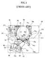
- Figure 1 is a plan view schematically showing a deck mechanism of a conventional magnetic recording/reproducing apparatus.
- a head drum 106, a loading motor 101, a cam gear 102 rotated by the driving force of loading motor 101, and a cam lever 104 interlocked with cam gear 102 are installed in a main deck 109.
- a first cam groove 103 and a second cam groove 103a are formed in cam gear 102.
- Cam lever 104 is interlocked with first cam groove 103.
- Loading grooves 116 and 116a for guiding pole bases 115 and 115a are formed in both sides of head drum 106.
- Sub-deck 105 is slidably installed in an upper portion of main deck 109 and moves slidingly up and down by cam lever 104.
- a slide member 110 coupled to a second cam groove 103a of cam gear 102 is installed between main deck 109 and sub-deck 105 and is guided by a guide pin 117 installed in main deck 109.
- pole bases 115 and 115a where a guide pin for guiding a tape is installed and loading arms 107 and 107a connected to the pole bases are rotatably installed in an upper surface of sub-deck 105, centering around rotating axes 114 and 114a, respectively.
- a reel table (not shown) where a tape cassette is loaded is installed in sub-deck 105.
- the reel table is selectively rotated by a driver (not shown) and is stopped by a brake (not shown).
- Loading arms 107 and 107a are respectively connected to levers 112 and 112a rotatably installed in slide member 110 by resilient members 111 and 111a.
- Sliders 108 and 108a of loading arms 107 and 107a slidably contact pins 113 and 113a installed in levers 112 and 112a, respectively.
- the thus-structured conventional magnetic recording/reproducing apparatus operates as follows.
- cam gear 102 rotates via a series of gears.
- sub-deck 105 where a tape cassette (not shown) is loaded moves toward head drum 106 by cam lever 104 that rotates in accordance with first cam groove 103.
- slide member 110 moves toward head drum 106 by the rotating cam gear 102.
- loading arms 107 and 107a rotate as sliding portions 108 and 108a contact pins 113 and 113a, respectively.
- guiding members 211, 212, 213 and 214 installed in pole bases 115 and 115a withdraws a tape from a tape cassette.
- pole bases 115 and 115a move along loading grooves 116 and 116a so that a tape contacts head drum 106. In such a state, head drum 106 rotates and the tape travels, to thereby perform a magnetic recording/reproducing operation.
- slide member 110 drives only pole bases 115 and 115a.
- the reel table stops by a brake.
- the deck mechanism of the conventional magnetic recording/reproducing apparatus operators for driving each element should be separately installed. Accordingly, the structure is complicated and production costs are high, which makes product miniaturization difficult.
- a deck mechanism of a magnetic recording/reproducing apparatus comprising: a main deck where a head drum with a magnetic head and a capstan motor are installed; a sub-deck where a supplying/take-up reel table slidably installed into an upper potion of the main deck and where a tape cassette is loaded, a brake member for braking said reel table, a pair of pole bases for ejecting a tape from said tape cassette and transmitting said tape toward said head drum, a connecting lever and a loading arm connected to each of said pole bases and rotatably installed, a pinch roller pressed onto a shaft of said capstan motor so as to press and transmit said tape, and a rotatable lever for supporting said pinch roller, are installed; moving means for moving said sub-deck; and operating means for integrally operating said brake member, pinch roller and pole bases.
- said moving means comprises: a driving motor installed in said main deck; a cam gear rotated by the driving force of said driving motor and where a first cam groove having a predetermined shape is formed; and a lever member whose ends are slidably coupled to said main deck and sub-deck, respectively, and whose intermediate portion is coupled to said first cam groove.
- said operating means comprises: a driving motor installed in said main deck; a cam gear rotated by the driving force of said driving motor and where a second cam groove is formed; and a slide member where a coupling pin slidably coupled to said second cam groove, third and fourth cam grooves whereto part of said pair of loading arms is slidably coupled, a fifth cam groove whereto said lever of said pinch roller is slidably coupled, and a plurality of contacting portions partially contacting said brake member, are formed, whereby said pole bases, brake and pinch roller selectively operate when said sub-deck moves.
- said pair of loading arms comprises guide pins coupled to said third and fourth cam grooves, and said third and fourth cam grooves includes first and second horizontal portions whereto said guide pins are guided horizontally and a vertical portion for connecting said first and second horizontal portions and whereto said guide pins are guided vertically.
- upper and lower loading grooves for guiding a movement of said pole bases are separately formed in said main deck and sub-deck, respectively.
- a pair of guide protrusions coupled to said loading grooves are formed at a bottom surface of said pole bases, and said upper loading groove comprises branch grooves whereto said pair of guide protrusions are respectively guided.
- said head drum is inclined toward the third quadrant of said head drum.
- said magnetic recording/reproducing apparatus further comprises a tension pole for tensioning the tape and which is installed in the sub-deck adjacent to said supply reel table, a tension arm for supporting said tension pole, and tension arm operating means for operating said tension arm.
- said tension arm operating means is constituted by a first guide groove formed in said main deck and a guide pin coupled to said first guide groove in said tension arm, and operated such a manner that said tension arm rotates by moving said guide pins along said first guide groove when said sub-deck moves up and down.
- said magnetic recording/reproducing apparatus further comprises a review pole installed in said sub-deck adjacent to said take-up reel table and for tensioning the tape, a review arm for supporting said review pole, and review arm operating means for operating said review arm.
- said review arm operating means is constituted by a second guide groove formed ins aid main deck and a guide pin to be coupled to said second guide groove in said review arm, and operated in such a manner that said review arm rotates by moving said guide pins along with said second guide groove when said sub-deck moves up and down.
- a deck mechanism of a magnetic recording/reproducing apparatus including a main deck where a head drum is installed, a sub-deck which moves with respect to the main deck and where a reel table is installed, and a slide member between the main deck and the sub-deck and which moves by the cam gear and selectively operates a pole base, brake and pinch roller.
- said deck mechanism of a magnetic recording/reproducing apparatus further comprises any one or more features of the accompanying description, claims, abstract and/or drawings, in any combination.
- a magnetic recording/reproducing apparatus characterised in that it comprises a deck mechanism according to the first or second aspect of the invention.
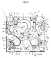
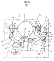
- a deck mechanism of a recording/reproducing apparatus of the present invention includes a main deck 1 fixed to a body (not shown), and a sub-deck 2 movable by predetermined moving means with respect to main deck 1.
- a head drum 6 having a magnetic head and a capstan motor 24 are installed in main deck 1.
- a tape guide roller 9 is installed in the left side of head drum 6.
- a capstan motor 24 is installed in a lower portion of main deck 1, and a shaft 15 protrudes upward from main deck 1.
- head drum 6 is inclined toward the third quadrant.
- a supply reel table 20 where a tape cassette 100 is loaded and a take-up reel table 24 are installed in sub-deck 2.
- a sub-brake 47 that frictionally contacts supply reel table 20, a weak brake 55 that frictionally contacts take-up reel table 24, and a main brake 54 for braking take-up reel table 24 are installed in sub-deck 2.
- Sub-brake 47 is rotatably installed into sub-deck 2, and includes a friction portion 50 that frictionally contacts an outer circumferential surface of take-up reel table 20 and a protrusion 51 protruding towards main deck 1, and is coupled to a resilient member 48 fixed onto sub-deck 2.
- Weak brake 55 is installed rotatably into sub-deck 2 and includes a resilient member 59 that frictionally contacts an outer circumferential surface of take-up reel table 24 and a protrusion 55a protruding downward from sub-deck 2.
- main brake 54 is rotatably installed in sub-deck 2 and comprises a brake 57 that strongly contacts an outer circumferential surface of take-up reel table 24 and a protrusion 58 protruded toward main deck 1.
- main brake 54 is coupled to resilient member 56 which is fixed onto sub-deck 2.
- a pair of pole bases 17 and 18 for ejecting a tape from tape cassette 100 and moving the tape toward head drum 6 are installed in sub-deck 2.
- First guide roller 10 and a first inclined pole 11 are installed in pole base 17, and second guide roller 13, second inclined pole 12 and third inclined pole 14 are installed in pole base 18.
- Loading arms 43 and 44 are rotatably installed in sub-deck 2, centering around rotation axes 43a and 44a.
- Connection levers 45 and 46 are rotatably connected to respective end portions of loading arms 43 and 44.
- pole bases 17 and 18 are rotatably connected to respective end portions of connecting levers 45 and 46.
- Connection levers 45 and 46 and pole bases 17 and 18 are resiliently biased by mutual resilient members 74 and 76.
- Guide pins 75 and 75a are installed in the bottom surface of loading arms 43 and 44, and guide grooves 2a and 2b for guiding guide pins 75 and 75a are formed in sub-deck 2.
- a pinch roller 73 which is pressed onto capstan motor shaft 15 so as to press and transmit a tape is installed in sub-deck 2.
- Pinch roller 73 is installed into lever 32 which is rotatably installed in sub-deck 2.
- Guide pin 64 protruding toward main deck 1 is installed in lever 32, and guide groove 64a whereto guide pin 64 is coupled is formed in sub-deck 2.
- a tension controller for providing a predetermined tension to a tape in a play mode and review mode is installed in sub-deck 2.
- a tension controller comprises a tension arm 19 which is adjacent to the left side of head drum 6 and rotatably installed in to sub-deck 2, a tension pole 8 installed in the leading end of tension arm 19, and a resilient member 19a for resiliently biasing tension arm 19 in one direction.
- a band brake member 49 that frictionally contacts an outer circumferential surface of supply reel table 20 is installed in tension arm 19.
- guide pin 60 protruding towards main deck 1 is installed in one side of tension arm 19, and a first guide groove 61 whereto guide pin 60 is coupled is formed in main deck 1.
- tension arm 19 rotates as tension pole 8 contacts the tape.
- a tension controller comprises a review arm 66 which is installed in sub-deck 2 rotatably at the right side of head drum 6, a review pole 16 installed in the leading end of review arm 66, and a guide pin 67 protruding toward main deck 1 in the other end of review arm 66.
- Guide groove 67a whereto guide pin 67 is coupled is formed in sub-deck 2.
- a second guide groove 65 whereto guide pin 67 is coupled is formed in main deck 1. Accordingly, when sub-deck 2 moves up and down, review arm 66 rotates since guide pin 67 is guided to second guide groove 65.
- first and second guide grooves 61 and 65 have a predetermined inclined portion or curvature.
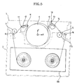
- upper loading grooves 22a and 23a whereto the pair of pole bases 17 and 18 are guided are formed in drum base 21 and main deck 1 in both sides of head drum 6.
- Lower loading grooves 22b and 23b connected to upper loading grooves 22a and 23a are formed in sub-deck 2.
- two guide protrusions 17a and 17b which are coupled to upper and lower loading grooves 22a, 23a, 22b and 23b are formed in a bottom surface of the left pole base 17.
- branch grooves 42 whereto guide protrusions 17a and 17b are guided are formed in the left upper loading groove 22a.
- a protrusion 41 is formed in an entrance of branch groove 42. Accordingly, left pole base 17 can be further rotated clockwise, centering around protrusion 41.
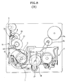
- operating means for moving sub-deck 2 operating brake members 47, 54 and 55, and moving pinch roller 73 and pole bases 17 and 18 operate as follows.
- driving motor 3 is installed in main deck 1.
- a decelerating gear 25 which is rotated by driving motor 3, a first gear 26, a second gear 27 and cam gear 4 are connected in series.
- Second gear 27 is provided with a mode switch (not shown) for controlling driving motor 3 for each mode.
- First and second cam grooves 29 and 30 having predetermined shapes are formed in cam gear 4.
- a cam lever 5 whose one end is slidably coupled to main deck 1, whose other end is slidably coupled to sub-deck 2, and whose middle portion is slidably coupled to first cam gear 29, is installed in an upper portion of cam gear 4.
- a protrusion 5a coupled to first cam groove 29 is formed in cam lever 5.
- protrusions 5b and 5c are formed in both ends of cam lever 5.
- Guide grooves 5d and 5e whereto protrusions 5c and 5b are coupled are formed respectively in sub-deck 2.
- cam lever 5 rotates along with first cam groove 29, to thereby move sub-deck 2 up and down.
- a slide member 7 where a coupling pin 7a slidably coupled to second cam groove 30 is formed is provided between main deck 1 and sub-deck 2.
- Guide slots 7b and 7c are formed in slide member 7, and protrusions 31 and 31a which are coupled to guide slots 7b and 7c are formed in main deck 1. Accordingly, slide member 7 is guided right and left.
- Third and fourth cam grooves 33 and 34 whereto guide pins 75 and 75a of loading arms 43 and 44 are slidably coupled and a fifth cam groove 35 whereto a guide pin 64 of pinch roller lever 32 is slidably coupled are formed in slide member 7.
- Third and fourth cam grooves 33 and 34 respectively comprise first and second horizontal portions 90, 91, 96 and 97 whereto guide pins 75 and 75a are horizontally guided and vertical portions 92 and 93 whereto guide pins 75 and 75a are vertically guided.
- inclined portions 94 and 95 having a predetermined inclination angle are provided between vertical portions 92 and 93 of third and fourth cam grooves 33 and 34 and second horizontal portions 96 and 97.
- fifth cam groove 35 includes a horizontal portion 98 whereto guide pin 64 of pinch roller lever 32 is horizontally guided, a vertical portion 99 whereto guide pin 64 of pinch roller lever 32 is vertically guided, and first and second inclined portions 100 and 101 which are inclined oppositely with respect to each other.
- a brake lever 70 for interlocking weak brake 55 with main brake 54 is rotatably installed at a bottom surface of sub-deck 2.
- Brake lever 70 is divided into two parts, and each end portion contacts protrusions 55a and 58 of brakes 55 and 54 respectively.
- Protrusions 70a and 70b are formed in end portions of brake lever 70.
- an eject lever 80 for releasing the locking of a housing (not shown) for receiving tape cassette 100 is rotatably installed at a bottom surface of sub-deck 2, centering around rotation axis 81.
- a protrusion 82 protruded downward is formed in an end portion of eject lever 80.
- a contacting portion 53 contacting protrusion 51 of sub-brake 47, contacting portions 53a and 53b contacting respectively protrusions 70a and 70b of brake lever 70 and a contacting portion 53c contacting protrusion 82 of eject lever 80 are protrudently formed.
- a capstan gear 24a rotated by capstan motor 24, and a pulley 37 connected to capstan gear 24a by a belt 38 so as to be rotated, are installed in main deck 1.
- Lever 37a is fixed onto pulley 37 and an idler gear 36 is rotatably installed in an end of lever 37a.
- Idler gear 36 is selectively meshed with supply reel table 20 or take-up reel table 24 according to the rotation direction of pulley 37.
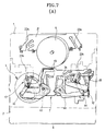
- the reference number 68 of Figure 2 and Figure 4 is an end sensor for sensing a non-magnetic surface of a tape.
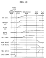
- the deck mechanism of the thus-structured magnetic recording/reproducing apparatus of the present invention operates as follows.
- an end sensor mode functions to slightly wind a tape onto a supply reel so that a tape can be smoothly ejected from tape cassette 100.
- tape cassette 100 where the tape is completely wound onto the supply reel is received into a housing (not shown).
- the housing is loaded by a loading apparatus which is not shown, and tape cassette 100 is loaded into reel tables 20 and 24.
- end sensor 68 senses a non-magnetic surface of the tape.
- driving motor 3 drives, decelerating gear 25, first and second gears 26 and 27 and cam gear 4 rotate. Then, cam gear 4 rotates counterclockwise to move slide member 7 to the right.
- An unloading mode immediately precedes a loading of the tape when the tape cassette is loaded into reel tables 20 and 24 as shown in Figure 7a.
- pole bases 17 and 18 move along lower loading grooves 22b and 23b by loading arms 43 and 44 and connecting levers 45 and 46.
- lower loading grooves 23b of sub-deck 2 and upper loading grooves 22a and 23a of main deck 1 are interconnected.
- pole bases 17 and 18 enter upper loading grooves 22a and 23a
- slide member 7 moves slightly to the left by the rotation of cam gear 4.
- guide pin 75 of left loading arm 43 passes through inclined portion 94 of third cam groove 33
- left pole base 17 enters upper loading groove 22a.
- pole base 17 slightly rotates clockwise by the resilience of resilient member 74, to thereby complete a loading operation.
- right pole base 18 enters upper loading groove 23a when guide pin 75a of loading arm 44 passes through inclined portion 95 of fourth cam groove 34.
- pole base 18 completes the loading by the resilience of resilient member 76.
- tension arm 19 rotates counterclockwise as guide pin 60 thereof is guided to first guide groove 61 formed in main deck 1.
- review arm 66 rotates clockwise as guide pin 67 is guided to second guide groove 65 formed in main deck 1.
- Tension pole 8 and review pole 16 which rotate along with the movement of sub-deck 2 eject the tape from tape cassette 100.
- a plurality of guiding elements installed in pole bases 17 and 18 which are transferred eject the tape from tape cassette 100 in a similar way.
- the plural guiding elements comprise first guide roller 10, first inclined pole 11, second guide roller 13, second inclined pole 12 and third inclined pole 14.
- a stop mode is a state where pinch roller 73 and capstan motor shaft 15 are slightly separated after the loading of pole bases 17 and 18 is completed, reel tables 20 and 24 are put on the brake by sub-brake 47, weak brake 55 and main brake 54, and tension pole 8 loosely contact the tape.
- This state is obtained when slide member 7 slightly moves to the right by a rotation of cam gear 4.
- guide pin 64 of pinch roller lever 32 contacts a second inclined portion 101 of fifth cam groove 35, to thereby rotate pinch roller lever 32 counterclockwise.
- tension arm 19 rotates clockwise to cam 62 of second gear 27 that rotates together with cam gear 4.
- contacting portions 53, 53a, 53b and 53c are each separated from brakes 47, 55 and 54.
- head drum 6 rotates and slide member 7 moves slightly to the left by a rotation of cam gear 4.
- sub-brake 47 is separated from supply reel table 20, and main brake 54 is separated from take-up reel table 24.
- weak brake 55 contacts an outer circumferential surface of take-up reel table 24.
- capstan motor 24 is driven.
- idler gear 36 is meshed with take-up reel tale 24 which is then rotated clockwise.
- a tape is wound to the take-up reel by pressure between capstan motor shaft 15 and pinch roller 73.
- the tape is wound onto the take-up reel via the supply reel and head drum 6 and reproduced.
- sub-deck 2 is transmitted downward by cam lever 5 when cam gear 4 rotates in the reverse direction.
- upper and lower loading grooves 22a, 23a, 22b and 23b are separated, and pole bases 17 and 18 are guided to third and fourth cam grooves 33 and 34 of slide member 7 to move along lower loading grooves 22b and 23b.
- protrusion 82 of eject lever 80 contacts contacting portion 53c, as eject lever 80 rotates.
- eject lever 80 releases the locking of a housing (not shown).
- the deck mechanism of a magnetic recording/reproducing apparatus of the present invention has certain distinct advantages.
- pole bases 17 and 18, a plurality of brakes 47, 54 and 55, and a pinch roller 73 are operated by a single slide member 7, to thereby simplify an apparatus structure.
- a head drum is installed to be inclined toward the third quadrant, to thereby shorten a loading distance of a tape cassette.
- a tape guider and a recording/reproducing element are divided and installed in a main deck and a sub-deck, and a plurality of elements operate by a single member, to thereby simplify the structure. Accordingly, a recording/reproducing apparatus can be miniaturized.
- the magnetic recording/reproducing apparatus having such advantages enables the manufacture of a miniaturized and lightweight product.
Landscapes
- Adjustment Of The Magnetic Head Position Track Following On Tapes (AREA)
- Registering, Tensioning, Guiding Webs, And Rollers Therefor (AREA)
- Braking Arrangements (AREA)
- Transmission Devices (AREA)
- Supply And Installment Of Electrical Components (AREA)
- Feeding And Guiding Record Carriers (AREA)
Applications Claiming Priority (4)
| Application Number | Priority Date | Filing Date | Title |
|---|---|---|---|
| KR1019940023861A KR0139364B1 (ko) | 1994-09-15 | 1994-09-15 | 캠코더의 폴 베이스 구동 장치 |
| KR9423861 | 1994-09-15 | ||
| KR1019940025937A KR0139365B1 (ko) | 1994-10-08 | 1994-10-08 | 캠코더 데크 구동장치 및 그 구동방법 |
| KR9425937 | 1994-10-08 |
Publications (3)
| Publication Number | Publication Date |
|---|---|
| EP0702362A2 true EP0702362A2 (fr) | 1996-03-20 |
| EP0702362A3 EP0702362A3 (fr) | 1997-02-26 |
| EP0702362B1 EP0702362B1 (fr) | 2001-08-01 |
Family
ID=26630570
Family Applications (1)
| Application Number | Title | Priority Date | Filing Date |
|---|---|---|---|
| EP95306390A Expired - Lifetime EP0702362B1 (fr) | 1994-09-15 | 1995-09-12 | Mécanisme d'entraínement d'appareil d'enregistrement/reproduction magnétique |
Country Status (8)
| Country | Link |
|---|---|
| US (1) | US5699208A (fr) |
| EP (1) | EP0702362B1 (fr) |
| JP (1) | JP3359795B2 (fr) |
| CN (1) | CN1115681C (fr) |
| CA (1) | CA2157985C (fr) |
| DE (1) | DE69521952T2 (fr) |
| ES (1) | ES2160670T3 (fr) |
| RU (1) | RU2155390C2 (fr) |
Cited By (8)
| Publication number | Priority date | Publication date | Assignee | Title |
|---|---|---|---|---|
| GB2320798A (en) * | 1996-12-30 | 1998-07-01 | Daewoo Electronics Co Ltd | Video tape loading apparatus |
| EP0944064A1 (fr) * | 1998-03-19 | 1999-09-22 | Matsushita Electric Industrial Co., Ltd. | Appareil d'enregistrement/reproduction magnétique |
| EP0944066A3 (fr) * | 1998-03-19 | 1999-11-03 | Matsushita Electric Industrial Co., Ltd. | Appareil d'enregistrement/reproduction magnétique |
| US6137649A (en) * | 1998-03-19 | 2000-10-24 | Matsushita Electric Industrial Co., Ltd. | Magnetic recording/reproduction apparatus in which one of a reel base pair is rotated to wind a magnetic tape by a predetermined amount when an abnormality is detected |
| US6198592B1 (en) | 1998-03-19 | 2001-03-06 | Matsushita Electric Industrial Co., Ltd. | Magnetic recording/reproduction apparatus including a first chassis onto which a tape cassette is received and a second chassis having a rotary head cylinder thereon |
| US6288865B1 (en) | 1998-03-19 | 2001-09-11 | Matshushita Electric Industrial Co. Ltd | Magnetic recording/reproduction apparatus having a mechanism for moving a sub-chassis relative to a main chassis |
| US6286775B1 (en) | 1998-03-19 | 2001-09-11 | Matsushita Electric Industrial Co. Ltd. | Magnetic recording apparatus |
| US6671122B2 (en) | 1998-03-19 | 2003-12-30 | Matsushita Electric Industrial Co., Ltd. | Magnetic recording/reproduction apparatus |
Families Citing this family (6)
| Publication number | Priority date | Publication date | Assignee | Title |
|---|---|---|---|---|
| JP3531461B2 (ja) * | 1998-03-19 | 2004-05-31 | 松下電器産業株式会社 | 磁気記録再生装置 |
| US6654199B1 (en) * | 1999-11-08 | 2003-11-25 | Canon Kabushiki Kaisha | Recording/reproducing apparatus with reduced number of guide posts |
| US7092201B2 (en) * | 2002-09-16 | 2006-08-15 | Samsung Electronics Co., Ltd. | Tape deck mechanism with main cam gear moving sub-deck, pole base loading unit, brake unit and main sliding memeber |
| KR100465223B1 (ko) * | 2002-09-16 | 2005-01-13 | 삼성전자주식회사 | 자기 기록/재생장치의 릴브레이크 조립체 |
| JP3915916B2 (ja) * | 2003-01-06 | 2007-05-16 | ソニー株式会社 | 記録再生装置 |
| RU2759348C1 (ru) * | 2020-12-15 | 2021-11-12 | Федеральное государственное бюджетное образовательное учреждение высшего образования "Воронежский государственный технический университет" | Исполнительный орган рулевого привода |
Family Cites Families (27)
| Publication number | Priority date | Publication date | Assignee | Title |
|---|---|---|---|---|
| NL8103831A (nl) * | 1981-08-17 | 1983-03-16 | Philips Nv | Magneetbandcassetteapparaat. |
| JPS5888856A (ja) * | 1981-11-20 | 1983-05-27 | Hitachi Ltd | カセツトテ−プレコ−ダのカセツト装着装置 |
| NL8201573A (nl) * | 1982-04-15 | 1983-11-01 | Philips Nv | Magneetband-loopwerk. |
| SU1332373A1 (ru) * | 1984-03-15 | 1987-08-23 | Предприятие П/Я В-8071 | Лентопрот жный механизм |
| JPS6185663A (ja) * | 1984-10-03 | 1986-05-01 | Hitachi Ltd | カセツト装着装置 |
| SU1280444A1 (ru) * | 1984-10-05 | 1986-12-30 | Предприятие П/Я В-8071 | Лентопрот жный механизм видеомагнитофона |
| JPH0413780Y2 (fr) * | 1985-03-28 | 1992-03-30 | ||
| JPS61163361U (fr) * | 1985-03-30 | 1986-10-09 | ||
| JPH0792958B2 (ja) * | 1985-05-27 | 1995-10-09 | ソニー株式会社 | カセツト式記録再生装置 |
| US4949203A (en) * | 1987-03-11 | 1990-08-14 | Pioneer Electronic Corporation | Tape recorder having an improved cassette mounting device |
| SU1531146A1 (ru) * | 1987-08-24 | 1989-12-23 | Предприятие П/Я В-8071 | Лентопрот жный тракт устройства наклонно-строчной видеозаписи ЕНИТ-88 |
| JPH071584B2 (ja) * | 1988-02-27 | 1995-01-11 | 三洋電機株式会社 | 磁気記録再生装置 |
| JPH0715771B2 (ja) * | 1988-08-30 | 1995-02-22 | 三洋電機株式会社 | 記録再生装置の駆動機構 |
| JP2669048B2 (ja) * | 1989-04-27 | 1997-10-27 | ソニー株式会社 | テープレコーダ |
| EP0395299B1 (fr) * | 1989-04-28 | 1995-11-15 | Sony Corporation | Système d'entraînement dans un appareil d'enregistrement et/ou de reproduction |
| JP2656618B2 (ja) * | 1989-06-14 | 1997-09-24 | 株式会社日立製作所 | 磁気記録再生装置 |
| JP2727665B2 (ja) * | 1989-06-21 | 1998-03-11 | ソニー株式会社 | テーププレーヤ |
| US5276567A (en) * | 1989-10-25 | 1994-01-04 | Tuner Company Limited | Tape player |
| US5218492A (en) * | 1990-06-14 | 1993-06-08 | Victor Company Of Japan, Ltd. | Magnetic recording and/or reproducing apparatus |
| JP2664281B2 (ja) * | 1990-11-09 | 1997-10-15 | 株式会社日立製作所 | 磁気記録再生装置 |
| AU652390B2 (en) * | 1990-11-30 | 1994-08-25 | Conner Peripherals, Inc | Narrow profile data storage cartridge tape drive of small overall size |
| KR930004448B1 (ko) * | 1990-12-06 | 1993-05-27 | 주식회사 금성사 | 자기기록테이프를 이용하는 기록 및 재생기의 브레이크 구동장치 |
| US5361180A (en) * | 1991-03-14 | 1994-11-01 | Sharp Kabushiki Kaisha | Simplified cassette loading mechanism for a magnetic recording and reproducing apparatus |
| JPH0512773A (ja) * | 1991-07-03 | 1993-01-22 | Sony Corp | テーププレーヤ |
| KR940001743B1 (ko) * | 1991-10-16 | 1994-03-05 | 삼성전자 주식회사 | 캠코더 데크의 구동장치 및 그 제어방법 |
| JPH05135452A (ja) * | 1991-11-08 | 1993-06-01 | Hitachi Ltd | テープローデイング装置 |
| KR950009662B1 (ko) * | 1992-01-16 | 1995-08-25 | 삼성전자주식회사 | 캠코더 데크 구동장치 및 그 제어방법 |
-
1995
- 1995-05-22 CN CN95106667A patent/CN1115681C/zh not_active Expired - Fee Related
- 1995-05-23 US US08/447,875 patent/US5699208A/en not_active Expired - Fee Related
- 1995-09-11 CA CA002157985A patent/CA2157985C/fr not_active Expired - Fee Related
- 1995-09-11 JP JP23299195A patent/JP3359795B2/ja not_active Expired - Fee Related
- 1995-09-12 RU RU95115539/28A patent/RU2155390C2/ru not_active IP Right Cessation
- 1995-09-12 ES ES95306390T patent/ES2160670T3/es not_active Expired - Lifetime
- 1995-09-12 DE DE69521952T patent/DE69521952T2/de not_active Expired - Fee Related
- 1995-09-12 EP EP95306390A patent/EP0702362B1/fr not_active Expired - Lifetime
Non-Patent Citations (1)
| Title |
|---|
| None |
Cited By (10)
| Publication number | Priority date | Publication date | Assignee | Title |
|---|---|---|---|---|
| GB2320798A (en) * | 1996-12-30 | 1998-07-01 | Daewoo Electronics Co Ltd | Video tape loading apparatus |
| US5982575A (en) * | 1996-12-30 | 1999-11-09 | Daewood Electronics Co. Ltd. | Tape loading apparatus with a pair of link devices having deformable bent portions |
| GB2320798B (en) * | 1996-12-30 | 2001-01-10 | Daewoo Electronics Co Ltd | Video cassette recorder equipped with a tape loading apparatus |
| EP0944064A1 (fr) * | 1998-03-19 | 1999-09-22 | Matsushita Electric Industrial Co., Ltd. | Appareil d'enregistrement/reproduction magnétique |
| EP0944066A3 (fr) * | 1998-03-19 | 1999-11-03 | Matsushita Electric Industrial Co., Ltd. | Appareil d'enregistrement/reproduction magnétique |
| US6137649A (en) * | 1998-03-19 | 2000-10-24 | Matsushita Electric Industrial Co., Ltd. | Magnetic recording/reproduction apparatus in which one of a reel base pair is rotated to wind a magnetic tape by a predetermined amount when an abnormality is detected |
| US6198592B1 (en) | 1998-03-19 | 2001-03-06 | Matsushita Electric Industrial Co., Ltd. | Magnetic recording/reproduction apparatus including a first chassis onto which a tape cassette is received and a second chassis having a rotary head cylinder thereon |
| US6288865B1 (en) | 1998-03-19 | 2001-09-11 | Matshushita Electric Industrial Co. Ltd | Magnetic recording/reproduction apparatus having a mechanism for moving a sub-chassis relative to a main chassis |
| US6286775B1 (en) | 1998-03-19 | 2001-09-11 | Matsushita Electric Industrial Co. Ltd. | Magnetic recording apparatus |
| US6671122B2 (en) | 1998-03-19 | 2003-12-30 | Matsushita Electric Industrial Co., Ltd. | Magnetic recording/reproduction apparatus |
Also Published As
| Publication number | Publication date |
|---|---|
| CA2157985A1 (fr) | 1996-03-16 |
| JP3359795B2 (ja) | 2002-12-24 |
| CN1151072A (zh) | 1997-06-04 |
| US5699208A (en) | 1997-12-16 |
| DE69521952T2 (de) | 2001-11-29 |
| JPH08190751A (ja) | 1996-07-23 |
| CA2157985C (fr) | 2003-05-06 |
| RU2155390C2 (ru) | 2000-08-27 |
| EP0702362A3 (fr) | 1997-02-26 |
| EP0702362B1 (fr) | 2001-08-01 |
| DE69521952D1 (de) | 2001-09-06 |
| ES2160670T3 (es) | 2001-11-16 |
| CN1115681C (zh) | 2003-07-23 |
Similar Documents
| Publication | Publication Date | Title |
|---|---|---|
| EP0702362B1 (fr) | Mécanisme d'entraínement d'appareil d'enregistrement/reproduction magnétique | |
| EP0404426B1 (fr) | Mécanisme de changement de mode de fonctionnement pour appareil d'enregistrement et/ou de reproduction à bande | |
| US5166843A (en) | Compact helical scan tape recording and/or reproducing apparatus | |
| CA1317579C (fr) | Methode de changement de mode pour appareil d'enregistrement et/ou de lecture de bande magnetique | |
| US6215610B1 (en) | Recording/reproducing apparatus with single motor for operating tape loading mechanism, pinch roller driving mechanism, reel driving mechanism, brake mechanism, and mode identifying mechanism | |
| EP0580031B1 (fr) | Appareil de sélection d'un mode de fonctionnement d'un système d'enregistrement et de reproduction pour un appareil d'enregistrement à cassette à bande | |
| JPH07169148A (ja) | ビデオカセットレコーダのリールテーブル駆動装置 | |
| US4985788A (en) | Recording and reproducing apparatus | |
| KR0176551B1 (ko) | 자기 기록/재생장치 | |
| US5691858A (en) | Magnetic recording and reproducing apparatus having a single master gear and slide member | |
| US5485324A (en) | Double-deck camcorder with perpendicularly installed head drum | |
| US5196971A (en) | Tape loading mechanism for use in magnetic recording/reproducing apparatus having tape control features for preventing damage to tape | |
| JP3878589B2 (ja) | 磁気記録/再生装置のデッキメカニズム | |
| JPS6230184Y2 (fr) | ||
| JP4333054B2 (ja) | テープローディング装置 | |
| KR0139365B1 (ko) | 캠코더 데크 구동장치 및 그 구동방법 | |
| JPH0792956B2 (ja) | 磁気テ−プ装置 | |
| JPH0421262B2 (fr) | ||
| EP0376242B1 (fr) | Mécanisme de chargement de cassette utilisé dans un appareil d'enregistrement/reproduction | |
| JPS6232364Y2 (fr) | ||
| KR940000858Y1 (ko) | 브이씨알의 고속화면 탐사를 위한 테이프 가이드장치 | |
| KR100277740B1 (ko) | 자기기록재생기의 권취측 폴 베이스 구동장치 | |
| JPS6117251A (ja) | 磁気記録再生装置 | |
| JP2603228B2 (ja) | 回転ヘツド型記録または再生装置 | |
| KR19990016390A (ko) | 자기 기록/재생 장치의 데크 메커니즘 |
Legal Events
| Date | Code | Title | Description |
|---|---|---|---|
| PUAI | Public reference made under article 153(3) epc to a published international application that has entered the european phase |
Free format text: ORIGINAL CODE: 0009012 |
|
| AK | Designated contracting states |
Kind code of ref document: A2 Designated state(s): DE ES FR GB IT NL |
|
| PUAL | Search report despatched |
Free format text: ORIGINAL CODE: 0009013 |
|
| AK | Designated contracting states |
Kind code of ref document: A3 Designated state(s): DE ES FR GB IT NL |
|
| 17P | Request for examination filed |
Effective date: 19970728 |
|
| 17Q | First examination report despatched |
Effective date: 19980618 |
|
| GRAG | Despatch of communication of intention to grant |
Free format text: ORIGINAL CODE: EPIDOS AGRA |
|
| GRAG | Despatch of communication of intention to grant |
Free format text: ORIGINAL CODE: EPIDOS AGRA |
|
| GRAH | Despatch of communication of intention to grant a patent |
Free format text: ORIGINAL CODE: EPIDOS IGRA |
|
| GRAH | Despatch of communication of intention to grant a patent |
Free format text: ORIGINAL CODE: EPIDOS IGRA |
|
| GRAA | (expected) grant |
Free format text: ORIGINAL CODE: 0009210 |
|
| AK | Designated contracting states |
Kind code of ref document: B1 Designated state(s): DE ES FR GB IT NL |
|
| REF | Corresponds to: |
Ref document number: 69521952 Country of ref document: DE Date of ref document: 20010906 |
|
| REG | Reference to a national code |
Ref country code: ES Ref legal event code: FG2A Ref document number: 2160670 Country of ref document: ES Kind code of ref document: T3 |
|
| ET | Fr: translation filed | ||
| REG | Reference to a national code |
Ref country code: GB Ref legal event code: IF02 |
|
| PLBE | No opposition filed within time limit |
Free format text: ORIGINAL CODE: 0009261 |
|
| STAA | Information on the status of an ep patent application or granted ep patent |
Free format text: STATUS: NO OPPOSITION FILED WITHIN TIME LIMIT |
|
| 26N | No opposition filed | ||
| PGFP | Annual fee paid to national office [announced via postgrant information from national office to epo] |
Ref country code: NL Payment date: 20080903 Year of fee payment: 14 Ref country code: IT Payment date: 20080926 Year of fee payment: 14 Ref country code: FR Payment date: 20080915 Year of fee payment: 14 |
|
| PGFP | Annual fee paid to national office [announced via postgrant information from national office to epo] |
Ref country code: GB Payment date: 20080917 Year of fee payment: 14 |
|
| PGFP | Annual fee paid to national office [announced via postgrant information from national office to epo] |
Ref country code: DE Payment date: 20080926 Year of fee payment: 14 |
|
| PGFP | Annual fee paid to national office [announced via postgrant information from national office to epo] |
Ref country code: ES Payment date: 20081021 Year of fee payment: 14 |
|
| REG | Reference to a national code |
Ref country code: NL Ref legal event code: V1 Effective date: 20100401 |
|
| GBPC | Gb: european patent ceased through non-payment of renewal fee |
Effective date: 20090912 |
|
| REG | Reference to a national code |
Ref country code: FR Ref legal event code: ST Effective date: 20100531 |
|
| PG25 | Lapsed in a contracting state [announced via postgrant information from national office to epo] |
Ref country code: NL Free format text: LAPSE BECAUSE OF NON-PAYMENT OF DUE FEES Effective date: 20100401 Ref country code: FR Free format text: LAPSE BECAUSE OF NON-PAYMENT OF DUE FEES Effective date: 20090930 Ref country code: DE Free format text: LAPSE BECAUSE OF NON-PAYMENT OF DUE FEES Effective date: 20100401 |
|
| PG25 | Lapsed in a contracting state [announced via postgrant information from national office to epo] |
Ref country code: GB Free format text: LAPSE BECAUSE OF NON-PAYMENT OF DUE FEES Effective date: 20090912 |
|
| PG25 | Lapsed in a contracting state [announced via postgrant information from national office to epo] |
Ref country code: IT Free format text: LAPSE BECAUSE OF NON-PAYMENT OF DUE FEES Effective date: 20090912 |
|
| REG | Reference to a national code |
Ref country code: ES Ref legal event code: FD2A Effective date: 20110715 |
|
| PG25 | Lapsed in a contracting state [announced via postgrant information from national office to epo] |
Ref country code: ES Free format text: LAPSE BECAUSE OF NON-PAYMENT OF DUE FEES Effective date: 20110705 |
|
| PG25 | Lapsed in a contracting state [announced via postgrant information from national office to epo] |
Ref country code: ES Free format text: LAPSE BECAUSE OF NON-PAYMENT OF DUE FEES Effective date: 20090913 |