EP0703837B1 - Ein verstärktes verbindungselement von verbundstrukturen und verfahren zum verbinden von verbundteilen - Google Patents
Ein verstärktes verbindungselement von verbundstrukturen und verfahren zum verbinden von verbundteilen Download PDFInfo
- Publication number
- EP0703837B1 EP0703837B1 EP19940914942 EP94914942A EP0703837B1 EP 0703837 B1 EP0703837 B1 EP 0703837B1 EP 19940914942 EP19940914942 EP 19940914942 EP 94914942 A EP94914942 A EP 94914942A EP 0703837 B1 EP0703837 B1 EP 0703837B1
- Authority
- EP
- European Patent Office
- Prior art keywords
- reinforcing elements
- joint
- composite
- adherent
- adherend
- Prior art date
- Legal status (The legal status is an assumption and is not a legal conclusion. Google has not performed a legal analysis and makes no representation as to the accuracy of the status listed.)
- Expired - Lifetime
Links
Images


Classifications
-
- C—CHEMISTRY; METALLURGY
- C04—CEMENTS; CONCRETE; ARTIFICIAL STONE; CERAMICS; REFRACTORIES
- C04B—LIME, MAGNESIA; SLAG; CEMENTS; COMPOSITIONS THEREOF, e.g. MORTARS, CONCRETE OR LIKE BUILDING MATERIALS; ARTIFICIAL STONE; CERAMICS; REFRACTORIES; TREATMENT OF NATURAL STONE
- C04B37/00—Joining burned ceramic articles with other burned ceramic articles or other articles by heating
- C04B37/008—Joining burned ceramic articles with other burned ceramic articles or other articles by heating by means of an interlayer consisting of an organic adhesive, e.g. phenol resin or pitch
-
- B—PERFORMING OPERATIONS; TRANSPORTING
- B29—WORKING OF PLASTICS; WORKING OF SUBSTANCES IN A PLASTIC STATE IN GENERAL
- B29C—SHAPING OR JOINING OF PLASTICS; SHAPING OF MATERIAL IN A PLASTIC STATE, NOT OTHERWISE PROVIDED FOR; AFTER-TREATMENT OF THE SHAPED PRODUCTS, e.g. REPAIRING
- B29C65/00—Joining or sealing of preformed parts, e.g. welding of plastics materials; Apparatus therefor
- B29C65/56—Joining or sealing of preformed parts, e.g. welding of plastics materials; Apparatus therefor using mechanical means or mechanical connections, e.g. form-fits
- B29C65/562—Joining or sealing of preformed parts, e.g. welding of plastics materials; Apparatus therefor using mechanical means or mechanical connections, e.g. form-fits using extra joining elements, i.e. which are not integral with the parts to be joined
- B29C65/564—Joining or sealing of preformed parts, e.g. welding of plastics materials; Apparatus therefor using mechanical means or mechanical connections, e.g. form-fits using extra joining elements, i.e. which are not integral with the parts to be joined hidden in the joint, e.g. dowels or Z-pins
-
- B—PERFORMING OPERATIONS; TRANSPORTING
- B29—WORKING OF PLASTICS; WORKING OF SUBSTANCES IN A PLASTIC STATE IN GENERAL
- B29C—SHAPING OR JOINING OF PLASTICS; SHAPING OF MATERIAL IN A PLASTIC STATE, NOT OTHERWISE PROVIDED FOR; AFTER-TREATMENT OF THE SHAPED PRODUCTS, e.g. REPAIRING
- B29C66/00—General aspects of processes or apparatus for joining preformed parts
- B29C66/01—General aspects dealing with the joint area or with the area to be joined
- B29C66/05—Particular design of joint configurations
- B29C66/10—Particular design of joint configurations particular design of the joint cross-sections
- B29C66/11—Joint cross-sections comprising a single joint-segment, i.e. one of the parts to be joined comprising a single joint-segment in the joint cross-section
- B29C66/112—Single lapped joints
-
- B—PERFORMING OPERATIONS; TRANSPORTING
- B29—WORKING OF PLASTICS; WORKING OF SUBSTANCES IN A PLASTIC STATE IN GENERAL
- B29C—SHAPING OR JOINING OF PLASTICS; SHAPING OF MATERIAL IN A PLASTIC STATE, NOT OTHERWISE PROVIDED FOR; AFTER-TREATMENT OF THE SHAPED PRODUCTS, e.g. REPAIRING
- B29C66/00—General aspects of processes or apparatus for joining preformed parts
- B29C66/01—General aspects dealing with the joint area or with the area to be joined
- B29C66/05—Particular design of joint configurations
- B29C66/10—Particular design of joint configurations particular design of the joint cross-sections
- B29C66/13—Single flanged joints; Fin-type joints; Single hem joints; Edge joints; Interpenetrating fingered joints; Other specific particular designs of joint cross-sections not provided for in groups B29C66/11 - B29C66/12
- B29C66/131—Single flanged joints, i.e. one of the parts to be joined being rigid and flanged in the joint area
-
- B—PERFORMING OPERATIONS; TRANSPORTING
- B29—WORKING OF PLASTICS; WORKING OF SUBSTANCES IN A PLASTIC STATE IN GENERAL
- B29C—SHAPING OR JOINING OF PLASTICS; SHAPING OF MATERIAL IN A PLASTIC STATE, NOT OTHERWISE PROVIDED FOR; AFTER-TREATMENT OF THE SHAPED PRODUCTS, e.g. REPAIRING
- B29C66/00—General aspects of processes or apparatus for joining preformed parts
- B29C66/70—General aspects of processes or apparatus for joining preformed parts characterised by the composition, physical properties or the structure of the material of the parts to be joined; Joining with non-plastics material
- B29C66/72—General aspects of processes or apparatus for joining preformed parts characterised by the composition, physical properties or the structure of the material of the parts to be joined; Joining with non-plastics material characterised by the structure of the material of the parts to be joined
- B29C66/721—Fibre-reinforced materials
-
- B—PERFORMING OPERATIONS; TRANSPORTING
- B29—WORKING OF PLASTICS; WORKING OF SUBSTANCES IN A PLASTIC STATE IN GENERAL
- B29C—SHAPING OR JOINING OF PLASTICS; SHAPING OF MATERIAL IN A PLASTIC STATE, NOT OTHERWISE PROVIDED FOR; AFTER-TREATMENT OF THE SHAPED PRODUCTS, e.g. REPAIRING
- B29C66/00—General aspects of processes or apparatus for joining preformed parts
- B29C66/80—General aspects of machine operations or constructions and parts thereof
- B29C66/81—General aspects of the pressing elements, i.e. the elements applying pressure on the parts to be joined in the area to be joined, e.g. the welding jaws or clamps
- B29C66/814—General aspects of the pressing elements, i.e. the elements applying pressure on the parts to be joined in the area to be joined, e.g. the welding jaws or clamps characterised by the design of the pressing elements, e.g. of the welding jaws or clamps
- B29C66/8145—General aspects of the pressing elements, i.e. the elements applying pressure on the parts to be joined in the area to be joined, e.g. the welding jaws or clamps characterised by the design of the pressing elements, e.g. of the welding jaws or clamps characterised by the constructional aspects of the pressing elements, e.g. of the welding jaws or clamps
- B29C66/81455—General aspects of the pressing elements, i.e. the elements applying pressure on the parts to be joined in the area to be joined, e.g. the welding jaws or clamps characterised by the design of the pressing elements, e.g. of the welding jaws or clamps characterised by the constructional aspects of the pressing elements, e.g. of the welding jaws or clamps being a fluid inflatable bag or bladder, a diaphragm or a vacuum bag for applying isostatic pressure
-
- B—PERFORMING OPERATIONS; TRANSPORTING
- B29—WORKING OF PLASTICS; WORKING OF SUBSTANCES IN A PLASTIC STATE IN GENERAL
- B29C—SHAPING OR JOINING OF PLASTICS; SHAPING OF MATERIAL IN A PLASTIC STATE, NOT OTHERWISE PROVIDED FOR; AFTER-TREATMENT OF THE SHAPED PRODUCTS, e.g. REPAIRING
- B29C70/00—Shaping composites, i.e. plastics material comprising reinforcements, fillers or preformed parts, e.g. inserts
- B29C70/04—Shaping composites, i.e. plastics material comprising reinforcements, fillers or preformed parts, e.g. inserts comprising reinforcements only, e.g. self-reinforcing plastics
- B29C70/28—Shaping operations therefor
- B29C70/54—Component parts, details or accessories; Auxiliary operations, e.g. feeding or storage of prepregs or SMC after impregnation or during ageing
- B29C70/543—Fixing the position or configuration of fibrous reinforcements before or during moulding
-
- C—CHEMISTRY; METALLURGY
- C04—CEMENTS; CONCRETE; ARTIFICIAL STONE; CERAMICS; REFRACTORIES
- C04B—LIME, MAGNESIA; SLAG; CEMENTS; COMPOSITIONS THEREOF, e.g. MORTARS, CONCRETE OR LIKE BUILDING MATERIALS; ARTIFICIAL STONE; CERAMICS; REFRACTORIES; TREATMENT OF NATURAL STONE
- C04B37/00—Joining burned ceramic articles with other burned ceramic articles or other articles by heating
- C04B37/003—Joining burned ceramic articles with other burned ceramic articles or other articles by heating by means of an interlayer consisting of a combination of materials selected from glass, or ceramic material with metals, metal oxides or metal salts
- C04B37/006—Joining burned ceramic articles with other burned ceramic articles or other articles by heating by means of an interlayer consisting of a combination of materials selected from glass, or ceramic material with metals, metal oxides or metal salts consisting of metals or metal salts
-
- B—PERFORMING OPERATIONS; TRANSPORTING
- B29—WORKING OF PLASTICS; WORKING OF SUBSTANCES IN A PLASTIC STATE IN GENERAL
- B29C—SHAPING OR JOINING OF PLASTICS; SHAPING OF MATERIAL IN A PLASTIC STATE, NOT OTHERWISE PROVIDED FOR; AFTER-TREATMENT OF THE SHAPED PRODUCTS, e.g. REPAIRING
- B29C66/00—General aspects of processes or apparatus for joining preformed parts
- B29C66/70—General aspects of processes or apparatus for joining preformed parts characterised by the composition, physical properties or the structure of the material of the parts to be joined; Joining with non-plastics material
- B29C66/71—General aspects of processes or apparatus for joining preformed parts characterised by the composition, physical properties or the structure of the material of the parts to be joined; Joining with non-plastics material characterised by the composition of the plastics material of the parts to be joined
-
- B—PERFORMING OPERATIONS; TRANSPORTING
- B29—WORKING OF PLASTICS; WORKING OF SUBSTANCES IN A PLASTIC STATE IN GENERAL
- B29C—SHAPING OR JOINING OF PLASTICS; SHAPING OF MATERIAL IN A PLASTIC STATE, NOT OTHERWISE PROVIDED FOR; AFTER-TREATMENT OF THE SHAPED PRODUCTS, e.g. REPAIRING
- B29C66/00—General aspects of processes or apparatus for joining preformed parts
- B29C66/70—General aspects of processes or apparatus for joining preformed parts characterised by the composition, physical properties or the structure of the material of the parts to be joined; Joining with non-plastics material
- B29C66/72—General aspects of processes or apparatus for joining preformed parts characterised by the composition, physical properties or the structure of the material of the parts to be joined; Joining with non-plastics material characterised by the structure of the material of the parts to be joined
- B29C66/721—Fibre-reinforced materials
- B29C66/7212—Fibre-reinforced materials characterised by the composition of the fibres
-
- C—CHEMISTRY; METALLURGY
- C04—CEMENTS; CONCRETE; ARTIFICIAL STONE; CERAMICS; REFRACTORIES
- C04B—LIME, MAGNESIA; SLAG; CEMENTS; COMPOSITIONS THEREOF, e.g. MORTARS, CONCRETE OR LIKE BUILDING MATERIALS; ARTIFICIAL STONE; CERAMICS; REFRACTORIES; TREATMENT OF NATURAL STONE
- C04B2237/00—Aspects relating to ceramic laminates or to joining of ceramic articles with other articles by heating
- C04B2237/02—Aspects relating to interlayers, e.g. used to join ceramic articles with other articles by heating
- C04B2237/12—Metallic interlayers
-
- C—CHEMISTRY; METALLURGY
- C04—CEMENTS; CONCRETE; ARTIFICIAL STONE; CERAMICS; REFRACTORIES
- C04B—LIME, MAGNESIA; SLAG; CEMENTS; COMPOSITIONS THEREOF, e.g. MORTARS, CONCRETE OR LIKE BUILDING MATERIALS; ARTIFICIAL STONE; CERAMICS; REFRACTORIES; TREATMENT OF NATURAL STONE
- C04B2237/00—Aspects relating to ceramic laminates or to joining of ceramic articles with other articles by heating
- C04B2237/30—Composition of layers of ceramic laminates or of ceramic or metallic articles to be joined by heating, e.g. Si substrates
- C04B2237/32—Ceramic
- C04B2237/36—Non-oxidic
- C04B2237/363—Carbon
-
- C—CHEMISTRY; METALLURGY
- C04—CEMENTS; CONCRETE; ARTIFICIAL STONE; CERAMICS; REFRACTORIES
- C04B—LIME, MAGNESIA; SLAG; CEMENTS; COMPOSITIONS THEREOF, e.g. MORTARS, CONCRETE OR LIKE BUILDING MATERIALS; ARTIFICIAL STONE; CERAMICS; REFRACTORIES; TREATMENT OF NATURAL STONE
- C04B2237/00—Aspects relating to ceramic laminates or to joining of ceramic articles with other articles by heating
- C04B2237/30—Composition of layers of ceramic laminates or of ceramic or metallic articles to be joined by heating, e.g. Si substrates
- C04B2237/40—Metallic
-
- C—CHEMISTRY; METALLURGY
- C04—CEMENTS; CONCRETE; ARTIFICIAL STONE; CERAMICS; REFRACTORIES
- C04B—LIME, MAGNESIA; SLAG; CEMENTS; COMPOSITIONS THEREOF, e.g. MORTARS, CONCRETE OR LIKE BUILDING MATERIALS; ARTIFICIAL STONE; CERAMICS; REFRACTORIES; TREATMENT OF NATURAL STONE
- C04B2237/00—Aspects relating to ceramic laminates or to joining of ceramic articles with other articles by heating
- C04B2237/50—Processing aspects relating to ceramic laminates or to the joining of ceramic articles with other articles by heating
- C04B2237/56—Using constraining layers before or during sintering
- C04B2237/567—Using constraining layers before or during sintering made of metal
-
- C—CHEMISTRY; METALLURGY
- C04—CEMENTS; CONCRETE; ARTIFICIAL STONE; CERAMICS; REFRACTORIES
- C04B—LIME, MAGNESIA; SLAG; CEMENTS; COMPOSITIONS THEREOF, e.g. MORTARS, CONCRETE OR LIKE BUILDING MATERIALS; ARTIFICIAL STONE; CERAMICS; REFRACTORIES; TREATMENT OF NATURAL STONE
- C04B2237/00—Aspects relating to ceramic laminates or to joining of ceramic articles with other articles by heating
- C04B2237/50—Processing aspects relating to ceramic laminates or to the joining of ceramic articles with other articles by heating
- C04B2237/56—Using constraining layers before or during sintering
- C04B2237/568—Using constraining layers before or during sintering made of non-oxide ceramics
-
- C—CHEMISTRY; METALLURGY
- C04—CEMENTS; CONCRETE; ARTIFICIAL STONE; CERAMICS; REFRACTORIES
- C04B—LIME, MAGNESIA; SLAG; CEMENTS; COMPOSITIONS THEREOF, e.g. MORTARS, CONCRETE OR LIKE BUILDING MATERIALS; ARTIFICIAL STONE; CERAMICS; REFRACTORIES; TREATMENT OF NATURAL STONE
- C04B2237/00—Aspects relating to ceramic laminates or to joining of ceramic articles with other articles by heating
- C04B2237/50—Processing aspects relating to ceramic laminates or to the joining of ceramic articles with other articles by heating
- C04B2237/59—Aspects relating to the structure of the interlayer
- C04B2237/592—Aspects relating to the structure of the interlayer whereby the interlayer is not continuous, e.g. not the whole surface of the smallest substrate is covered by the interlayer
-
- C—CHEMISTRY; METALLURGY
- C04—CEMENTS; CONCRETE; ARTIFICIAL STONE; CERAMICS; REFRACTORIES
- C04B—LIME, MAGNESIA; SLAG; CEMENTS; COMPOSITIONS THEREOF, e.g. MORTARS, CONCRETE OR LIKE BUILDING MATERIALS; ARTIFICIAL STONE; CERAMICS; REFRACTORIES; TREATMENT OF NATURAL STONE
- C04B2237/00—Aspects relating to ceramic laminates or to joining of ceramic articles with other articles by heating
- C04B2237/50—Processing aspects relating to ceramic laminates or to the joining of ceramic articles with other articles by heating
- C04B2237/82—Two substrates not completely covering each other, e.g. two plates in a staggered position
-
- C—CHEMISTRY; METALLURGY
- C04—CEMENTS; CONCRETE; ARTIFICIAL STONE; CERAMICS; REFRACTORIES
- C04B—LIME, MAGNESIA; SLAG; CEMENTS; COMPOSITIONS THEREOF, e.g. MORTARS, CONCRETE OR LIKE BUILDING MATERIALS; ARTIFICIAL STONE; CERAMICS; REFRACTORIES; TREATMENT OF NATURAL STONE
- C04B2237/00—Aspects relating to ceramic laminates or to joining of ceramic articles with other articles by heating
- C04B2237/50—Processing aspects relating to ceramic laminates or to the joining of ceramic articles with other articles by heating
- C04B2237/86—Joining of two substrates at their largest surfaces, one surface being complete joined and covered, the other surface not, e.g. a small plate joined at it's largest surface on top of a larger plate
-
- Y—GENERAL TAGGING OF NEW TECHNOLOGICAL DEVELOPMENTS; GENERAL TAGGING OF CROSS-SECTIONAL TECHNOLOGIES SPANNING OVER SEVERAL SECTIONS OF THE IPC; TECHNICAL SUBJECTS COVERED BY FORMER USPC CROSS-REFERENCE ART COLLECTIONS [XRACs] AND DIGESTS
- Y10—TECHNICAL SUBJECTS COVERED BY FORMER USPC
- Y10T—TECHNICAL SUBJECTS COVERED BY FORMER US CLASSIFICATION
- Y10T428/00—Stock material or miscellaneous articles
- Y10T428/19—Sheets or webs edge spliced or joined
- Y10T428/192—Sheets or webs coplanar
- Y10T428/193—Double faced corrugated sheets or webs connected
-
- Y—GENERAL TAGGING OF NEW TECHNOLOGICAL DEVELOPMENTS; GENERAL TAGGING OF CROSS-SECTIONAL TECHNOLOGIES SPANNING OVER SEVERAL SECTIONS OF THE IPC; TECHNICAL SUBJECTS COVERED BY FORMER USPC CROSS-REFERENCE ART COLLECTIONS [XRACs] AND DIGESTS
- Y10—TECHNICAL SUBJECTS COVERED BY FORMER USPC
- Y10T—TECHNICAL SUBJECTS COVERED BY FORMER US CLASSIFICATION
- Y10T428/00—Stock material or miscellaneous articles
- Y10T428/249921—Web or sheet containing structurally defined element or component
- Y10T428/249924—Noninterengaged fiber-containing paper-free web or sheet which is not of specified porosity
- Y10T428/24994—Fiber embedded in or on the surface of a polymeric matrix
- Y10T428/24995—Two or more layers
-
- Y—GENERAL TAGGING OF NEW TECHNOLOGICAL DEVELOPMENTS; GENERAL TAGGING OF CROSS-SECTIONAL TECHNOLOGIES SPANNING OVER SEVERAL SECTIONS OF THE IPC; TECHNICAL SUBJECTS COVERED BY FORMER USPC CROSS-REFERENCE ART COLLECTIONS [XRACs] AND DIGESTS
- Y10—TECHNICAL SUBJECTS COVERED BY FORMER USPC
- Y10T—TECHNICAL SUBJECTS COVERED BY FORMER US CLASSIFICATION
- Y10T428/00—Stock material or miscellaneous articles
- Y10T428/29—Coated or structually defined flake, particle, cell, strand, strand portion, rod, filament, macroscopic fiber or mass thereof
- Y10T428/2913—Rod, strand, filament or fiber
- Y10T428/2973—Particular cross section
- Y10T428/2975—Tubular or cellular
-
- Y—GENERAL TAGGING OF NEW TECHNOLOGICAL DEVELOPMENTS; GENERAL TAGGING OF CROSS-SECTIONAL TECHNOLOGIES SPANNING OVER SEVERAL SECTIONS OF THE IPC; TECHNICAL SUBJECTS COVERED BY FORMER USPC CROSS-REFERENCE ART COLLECTIONS [XRACs] AND DIGESTS
- Y10—TECHNICAL SUBJECTS COVERED BY FORMER USPC
- Y10T—TECHNICAL SUBJECTS COVERED BY FORMER US CLASSIFICATION
- Y10T428/00—Stock material or miscellaneous articles
- Y10T428/29—Coated or structually defined flake, particle, cell, strand, strand portion, rod, filament, macroscopic fiber or mass thereof
- Y10T428/2982—Particulate matter [e.g., sphere, flake, etc.]
- Y10T428/2991—Coated
- Y10T428/2993—Silicic or refractory material containing [e.g., tungsten oxide, glass, cement, etc.]
-
- Y—GENERAL TAGGING OF NEW TECHNOLOGICAL DEVELOPMENTS; GENERAL TAGGING OF CROSS-SECTIONAL TECHNOLOGIES SPANNING OVER SEVERAL SECTIONS OF THE IPC; TECHNICAL SUBJECTS COVERED BY FORMER USPC CROSS-REFERENCE ART COLLECTIONS [XRACs] AND DIGESTS
- Y10—TECHNICAL SUBJECTS COVERED BY FORMER USPC
- Y10T—TECHNICAL SUBJECTS COVERED BY FORMER US CLASSIFICATION
- Y10T428/00—Stock material or miscellaneous articles
- Y10T428/30—Self-sustaining carbon mass or layer with impregnant or other layer
Definitions
- the invention relates to a method for joining two parts at least one of which being a composite part.
- Composite laminate structures have been widely used and generally comprise layers of plies each including an array of fibers in a resin matrix.
- Prior art methods of joining two or more composite structures or components include the use of epoxies for low temperature joints and silver base braze alloys for intermediate temperature joints.
- Hoko U.S.No. 5,021,107 found, however, that for high temperature applications, wherein carbon-carbon composite component joints must withstand temperatures as high as 3000°F, an interlayer material used in the joint between the components, such as TiSi 2 , vacuum furnace brazed, resulted in an improved joint. But still, failures occur at the joint or even between the first few plies of the composite material.
- US Patent 4 528 051 discloses a method of reinforcing a laminate by interposing a pin carrier between two laminate structures and pressing them together such the pins are urged through the structures.
- the pin carrier being provided only on one side thereof with pins, is pressed to the laminate structure by an application roller exerting the pressure necessary to drive the pins into the laminate structure.
- US-Patent 4 808 461 describes a method for reinforcing composite laminate structures by urging reinforcing pins through the thickness of the laminate structure and removing those portions of the pins which extend beyond the surface of the structure. It is also suggested there to reinforce the laminate structure by applying thereto stiffening stringers having flat portions thereof laying on the laminate structure with reinforcing pins traversing those portions as well as the laminate structure.
- US Patents 4 015 035 and 4 709 714 describe joints between the ends of flat belt-like materials being provided with reinforcing fibers extending lengthwise inside of the belt.
- portions thereof are being etched away so as to expose the fiber ends, and then the belt ends are moved together such that the exposed fibers of one end extend between the exposed fibers of the other end.
- An adhesive is either disposed between the ends prior to moving them to each other or is applied to the interstitial arrangement of the fiber ends after putting them together.
- translaminar reinforcement of the composite structure including fibers disposed through the thickness of the structure
- strength of a joint between two such reinforced composite structures can be achieved by leaving the translaminar reinforcing fibers exposed at the surface of the structure at the joint region and then flowing a braze or other adherent material into the joint region and about the exposed fibers, and the further realization that in some cases the adherent material can be urged partially along the length of the reinforcing fibers and into each structure thereby providing a more cohesive bond at the joint region.
- This invention features a method of joining composite parts according to claim 1 including the steps of disposing a plurality of reinforcing elements through the thickness of two composite adherends to be joined wherein at least a number of the reinforcing elements are left extending from the joint surface or just left exposed at the joint surface of each adherend.
- the adherends are assembled so that the joint surface of one adherend faces the joint surface of the other adherend defining a joint region therebetween and wherein the extending reinforcing elements are interstitially disposed in the joint region.
- an adherend is disposed within the joint region about the interstitially disposed reinforcing elements and the joint surfaces for a reinforced joint between the composite parts.
- the adherends may be carbon-carbon composite structures and the reinforcing elements may be boron fibers. In such an embodiment, the adherent is a metallic braze material.
- the method of the invention gives rise to a joined composite part structure comprising a pair of composite adherends each including a plurality of reinforcing elements disposed through the thickness thereof wherein at least a number of the reinforcing elements are left extending from the joint surface of each adherend. Further included is a joint region between the adherends bounded by the joint surface of each adherend and including the extending reinforcing elements interstitially disposed therein. An adherent, about the extending interstitially disposed reinforcing elements, and between the joint surfaces within the joint region completes the joint between the two composite parts.
- This invention also features a method of joining composite parts comprising disposing a plurality of reinforcing elements through the thickness of two composite adherends, wherein the reinforcing elements are left extending from the joint surface of each adherend; assembling the adherends so that the joint surface of one adherend faces the joint surface of the other adherend; disposing an adherent interlayer between the opposing joint surfaces; and urging the extending reinforcing elements of each adherend through the adherent interlayer and interstitially locking the reinforcing elements therein.
- the adherent interlayer is a prepreg material
- the method further includes a step of curing the prepreg material to lock the reinforcing elements therein.
- a joined composite structure including a pair of composite adherends wherein only one adherend includes a plurality of reinforcing elements disposed through the thickness thereof and extending from the joint surface.
- a joint region between the adherends includes the joint surface of each adherend and the extending reinforcing elements of the one adherend disposed against the joint surface of the other adherend wherein an adherent is disposed in the joint region about the extending reinforcing elements and between the joint surfaces.
- a method of making such a joined composite part includes disposing a plurality of reinforcing elements through the thickness of a first composite adherend to be joined wherein at least a number of the reinforcing elements are left extending from the joint surface thereof; assembling the first adherend with the second adherend such that the joint surface of the first adherend faces the joint surface of the second adherend at the joint region therebetween and the extending elements of the first adherend are disposed against the joint surface of the second adherend; and finally disposing an adherent within the joint region.
- an interlayer adherent may be disposed between the opposing joint surfaces and the extending reinforcing elements of the first adherend may be urged through the adherent interlayer and against the joint surface of the second adherent for locking the reinforcing elements in the adherent interlayer.
- the adherent material is a prepreg material
- the method further includes a step of curing the prepreg material.
- This invention also features a particular embodiment involving joining a composite part with a non-composite part comprising inserting through the thickness of the composite part, a plurality of reinforcing elements at least at the joint region thereof; assembling the composite part such that the reinforcing elements are disposed proximate the joint surface of the non-composite part; and brazing the joint surfaces and the reinforcing elements to form a joint.
- This invention also features a method of joining composite parts wherein the braze material is selected to be compatible with the composite parts and the reinforcing elements. If the adherent interlayer methodology is used, a prepreg material may be selected and cured by subjecting the joined assembly to elevated pressure and temperature cycles.
- This invention features a particular embodiment involving joining composite parts with non-composite parts including inserting, through the thickness of the composite parts, a plurality of reinforcing elements at least at the joint region thereof; assembling the composite parts such that the reinforcing elements are disposed proximate the joint surface of the non-composite part; and brazing the joint surfaces and urging braze material to flow along the lengths of the reinforcing elements into the composite part.
- this invention features a joined structure including two adherends.
- the first adherend has reinforcing elements left exposed at the joint surface (extended, flush, or recessed), and the joint surface of the second adherend is disposed proximate the exposed reinforcing elements of the first adherend.
- An adherent about the exposed reinforcing elements and the joints surfaces secures the two structures and results in an improved bond between the two parts.
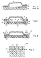
- Joining one composite part such as stiffener 5, Fig. 1, to composite structure 7 in the prior art utilizes adhesive or brazing material 8 between the parts at the joining surfaces.
- adhesive or brazing material 8 between the parts at the joining surfaces.
- a joint 9 is subject to delamination. If the joint is stronger than the laminated layers of composite part 7, delamination of the top plies 4 as shown at 6 may occur.
- adherend denotes one part or structure to be joined with another part or structure.
- the reinforcing elements 14 are exposed or even left extending as shown at 20.
- the reinforcing elements 16 are exposed as shown at 24. Outside of joint region, the reinforcing elements 15 may be filed flush as shown at 17.
- An adherent interlayer 26 such as film adhesive or prepreg material is then disposed between adherend 10 and adherend 12, and in one embodiment, pressure is used to drive extending reinforcing elements 16 and extending reinforcing elements 14 into adherent 26 which is then cured.
- one key improvement is that there is more surface area in the joint region 30 for adherent 26 to secure the joint surfaces of each part: that is, extending interstitially disposed reinforcing elements 32 to form a mechanical interlock which improves joint strength over prior methods where the adherent was secured only to the joint surfaces of each part.
- the adherent used may be urged partially up the length of the individual reinforcing elements as shown at 34 for even a more cohesive bond. The reinforcing elements, therefore, prevent surface ply delamination and improve the strength of joint 36.
- Reinforcing elements 32 may be boron, carbon, glass, organic or ceramic fibers, or metallic wires.
- both parts need not include extending reinforcing elements as shown for adherend 50, Fig. 6, which includes reinforcing elements 52 which are flush along joint surface 54.
- Adherend 56 includes reinforcing elements 58 which extend from joint surface 60.
- Adhesive or brazing adherent 62 is used to form joint 64.
- reinforcing elements 74 may be rendered flush along joint surface 76 and the resulting joint is still stronger than prior art methods since adherent 78 will seep partially down along reinforcing elements 74 as shown at 80.
- the reinforcing elements reduce delamination of surface ply 73 and also anchor the adherent within composite structure 72 along the lengths of reinforcing elements 74.
- the reinforcing elements 88, Fig. 8 may be left extending from joint surface 92 of composite part 86 disposed against joint surface 94 of non-composite stiffener 84 and adherent 90 bonds to the reinforcing elements 88 and joint surfaces 92 and 94. Therefore, the reinforcing elements may be left extending from both adherends, only one adherend, or a few reinforcing elements may be left extending at the joint surface and others could be disposed even slightly below the joint surface.
- carbon-carbon adherend 100, Fig. 9 comprising alternating layers of carbon weave material 102 and matrix material 104 may be joined with carbon-carbon adherend 106 wherein each adherend 100 and 106 includes carbon fiber rods or metallic wires 108 and 110 extending from joint surface 112 and 114 respectively.
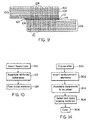
- the rods are first inserted into the carbon-carbon adherends 100 and 106 step 120, Fig. 10, and the reinforced adherends 100, 106, Fig. 9 are assembled, step 122, Fig. 10 such that the extending reinforcing rods are interstitially disposed at joint region 107, Fig. 9.
- Braze material 109 is then injected to flow into the joint region 107, step 124 so that the braze material 109 attaches to rods 108, 110 and also to carbon-carbon substrate 100, 106.
- the braze material 109 also travels up the rods providing a more cohesive bond between the rods and the carbon-carbon materials.
- Inserting the fibers, step 120, Fig. 10, may be accomplished as follows.
- Prepreg 230, Fig. 11, is assembled with reinforcing structure 210 on support tool 232.
- Reinforcing structure 210 includes a body 212 of polyvinyl foam material (Divinycell HT 110) that has a density of about 7 lbs/cubic foot and a thickness of about 8 mm.
- An array of rods or fibers 214 (each about 0.1 mm in diameter and 8 mm long) are disposed in body 212. Spacing between fibers 214 is about 1.5 mm.
- Support tool 232 is in communication with vacuum source 236, and film bag 238 enclosing release sheet 226, bleeder cloth 224, and cork damn 228 as well as prepreg 230 (epoxy AS 4/3501-6) with reinforcing structure 210 and support tool 230 is placed in autoclave 234.
- Vacuum bag 238, Fig. 12 is first initially evacuated by vacuum 236 to a pressure of 25 inches of mercury, and then an external pressure as indicated by arrows 240 of 85 Ibs/square inch is applied.
- the autoclave temperature is ramped up at a rate of 3-5 degrees per minute, to raise the temperature to 240°F while holding the autoclave pressure at 85 lbs. and the vacuum bag at about 25 in, of mercury.
- the temperature, pressure, and vacuum are held for about 1 hour.
- the vinyl body 212 begins to decompose and the autoclave pressure acting on pressure intensifying sheet 220 forces the fibers 214 through release plies 222, 226 and bleeder cloth 224 into laminate 230 in the Z direction.
- pressure intensifying sheet 220 forces the fibers 214 through release plies 222, 226 and bleeder cloth 224 into laminate 230 in the Z direction.
- pressure drives fibers 214 through the laminate 230 to impinge on support tool 232.
- the autoclave temperature is again raised at a rate of 3-5 degrees/minute to 350°F and held at the temperature and pressure for a cured interval of about two hours for curing the laminate.
- the temperature of the autoclave is lowered at a rate of about 5 degrees/minute to reduce the laminate temperature to 200°F.
- fabricating a reinforced joint for composite parts begins with the layup of each composite part, step 300, Fig. 14.
- plies of cloth phenolic prepreg including T300 carbon woven fiber prepreged with a phenolic resin are laid up to form the desired structural shape as is known.
- Titatium reinforcing elements are then inserted, step 302, at least at the joint regions as explained above in reference to Figs. 10-12 but may also be inserted throughout the structure or at area requiring added reinforcement.
- a certain percentage of phenolic resin turns to carbon. If required, the plies may be reimpregnated with phenolic resin and subjected to the autoclave process again after the reinforcing elements are inserted.
- step 304 Two such parts are then assembled, step 304 as described above: both having reinforcing elements extending from the joint surfaces, only one having reinforcing elements extending from its joint surface; or both parts having the reinforcing elements cut or filed flush depending on the application.
- a suitable braze material such as vanadium
- step 306 in the form of a foil or powder on a scrim and applied at the joint region. Baking for typically 10 minutes causes the braze material to flow around the extending reinforcing elements and also urges braze material partially down along the length of the reinforcing elements and into the structures at the joint region.
- an improved joint includes the joint surface of each part, the reinforcing elements, and the braze material.
- cured composite carbon-epoxy laminates having extending reinforcing elements at the joint region are assembled, step 304, and an interlayer adherent such as a prepreg material (AS 4/351-6) or film adhesive is selected, step 306.
- a vacuum bag curing process, step 308, similar to the autoclave process described above drives the reinforcing elements into the adhesive layer between the two parts and cures the resin about the reinforcing elements at the joint region for a strong joint between the two parts.
- a carbon-carbon or other composite part is to be joined with a metal or other non-composite stringer or reinforcement structure, such as is shown in Fig. 7 or Fig. 8, processing is similar except the braze or adherent chosen should be compatible with both the reinforcing elements of the composite part and the material of the reinforcing non-composite stringer.
- the design choice may warrant having reinforcing element 400, Fig. 15, left extending from joint surface 402 of adherent 404, reinforcing element 406 filed flush, or recessed reinforcing element 408 exposed as shown, or any combination of these choices.
- the adherent will then attach to the reinforcing element and the objects of this invention will be met.
Landscapes
- Engineering & Computer Science (AREA)
- Chemical & Material Sciences (AREA)
- Mechanical Engineering (AREA)
- Ceramic Engineering (AREA)
- Materials Engineering (AREA)
- Organic Chemistry (AREA)
- Structural Engineering (AREA)
- Textile Engineering (AREA)
- Composite Materials (AREA)
- Laminated Bodies (AREA)
- Lining Or Joining Of Plastics Or The Like (AREA)
- Ceramic Products (AREA)
- Joining Of Building Structures In Genera (AREA)
Claims (8)
- Verfahren zum Verbinden zweier Teile, von denen mindestens einer durch eine Laminatverbundstruktur gebildet wird, die allgemein lagenweise angeordnete Schichten enthält, von denen jede eine Anordnung von Fasern in einer Kunstharzmatrix enthält, wobei das Verfahren umfaßt:Einbringen einer Mehrzahl von extrinsischen Verstärkungselementen durch die Dicke mindestens eines Verbundteils an dessen Verbindungsbereich zur Vermeidung eines Aufblätterns der Schichten, wobei die Verstärkungselemente an der Verbindungsoberfläche frei bleiben;Zusammenfügen der Teile derart, daß die freiliegenden Verstärkungselemente sich nahe an der Verbindungsfläche des anderen Teils befinden; undVerteilen eines Haftmittels um die freiliegenden Verstärkungselemente und die Verbindungsoberflächen, wobei die freiliegenden Verstärkungselemente eine mechanische Eingriffsverbindung mit dem Haftmittel bilden und dadurch ein Trennen der beiden Teile verhindern.
- Verfahren nach Anspruch 1, bei welchem beide zu verbindenden Teile Verbundteile sind, gekennzeichnet durch
Einbringen einer Mehrzahl extrinsischer Verstärkungselemente durch die Dicke beider Verbundteile an deren Verbindungsbereich, wobei die Verstärkungselemente an der Verbindungsoberfläche frei bleiben;
Zusammenfügen der Verbundteile derart, daß die freiliegenden Verstärkungselemente in dem Verbindungsbereich auf Lücke angeordnet sind; und
Einbringen eines Haftmittels in den Verbindungsbereich um die auf Lücke angeordneten Verstärkungselemente und die miteinander verbundenen Oberflächen. - Verfahren nach Anspruch 1 oder 2, dadurch gekennzeichnet, daß das Haftmittel eine zwischen den verbundenen Oberflächen angeordnete Haftmittel-Zwischenschicht ist und daß die freiliegenden Verstärkungselemente durch die Haftmittel-Zwischenschicht hindurchgedrückt und in dieser festgehalten werden.
- Verfahren nach Anspruch 3, bei welchem die Haftmittel-Zwischenschicht ein vorimprägniertes (prepreg) Material ist und bei welchem das Verfahren weiterhin den Schritt des Aushärtens dieses Materials umfaßt.
- Verfahren nach einem der vorstehenden Ansprüche, dadurch gekennzeichnet, daß das Verbundteil eine Kohlenstoff-Kohlenstoff-Verbundstruktur ist.
- Verfahren nach einem der vorstehenden Ansprüche, bei welchem die Verstärkungselemente Fasern sind.
- Verfahren nach einem der vorstehenden Ansprüche, bei welchem das Haftmittel ein metallisches (Hart)Löt-Material ist.
- Verfahren nach einem der vorstehenden Ansprüche, dadurch gekennzeichnet, daß das Verbundteil durch ein Fasern in einer Kunstharzmatrix enthaltendes zu verbindendes Teil gebildet wird, bei welchem die Verstärkungselemente quer zur Faserrichtung eingesetzt sind und aus der Verbindungsoberfläche des Teils herausragen.
Applications Claiming Priority (3)
| Application Number | Priority Date | Filing Date | Title |
|---|---|---|---|
| US5602993A | 1993-04-30 | 1993-04-30 | |
| US56029 | 1993-04-30 | ||
| PCT/US1994/004733 WO1994025178A1 (en) | 1993-04-30 | 1994-04-29 | A reinforced joint for composite structures and method of joining composite parts |
Publications (3)
| Publication Number | Publication Date |
|---|---|
| EP0703837A1 EP0703837A1 (de) | 1996-04-03 |
| EP0703837A4 EP0703837A4 (de) | 1998-01-07 |
| EP0703837B1 true EP0703837B1 (de) | 2002-12-18 |
Family
ID=22001700
Family Applications (1)
| Application Number | Title | Priority Date | Filing Date |
|---|---|---|---|
| EP19940914942 Expired - Lifetime EP0703837B1 (de) | 1993-04-30 | 1994-04-29 | Ein verstärktes verbindungselement von verbundstrukturen und verfahren zum verbinden von verbundteilen |
Country Status (7)
| Country | Link |
|---|---|
| US (1) | US5667859A (de) |
| EP (1) | EP0703837B1 (de) |
| JP (1) | JPH08508235A (de) |
| AU (1) | AU671749B2 (de) |
| CA (1) | CA2161547A1 (de) |
| DE (1) | DE69431909T2 (de) |
| WO (1) | WO1994025178A1 (de) |
Families Citing this family (41)
| Publication number | Priority date | Publication date | Assignee | Title |
|---|---|---|---|---|
| JP3813654B2 (ja) * | 1995-02-09 | 2006-08-23 | 日本碍子株式会社 | セラミックスの接合構造およびその製造方法 |
| US6027798A (en) * | 1995-11-01 | 2000-02-22 | The Boeing Company | Pin-reinforced sandwich structure |
| US5789061A (en) * | 1996-02-13 | 1998-08-04 | Foster-Miller, Inc. | Stiffener reinforced assembly and method of manufacturing same |
| US5832594A (en) * | 1996-05-31 | 1998-11-10 | The Boeing Company | Tooling for inserting Z-pins |
| US5980665A (en) * | 1996-05-31 | 1999-11-09 | The Boeing Company | Z-pin reinforced bonds for connecting composite structures |
| US6128998A (en) | 1998-06-12 | 2000-10-10 | Foster Miller, Inc. | Continuous intersecting braided composite structure and method of making same |
| US6267175B1 (en) * | 2000-02-08 | 2001-07-31 | Honeywell International Inc. | Composite heat exchanger having strengthened joints |
| GB0003344D0 (en) * | 2000-02-14 | 2000-04-05 | Lotus Car | A method of joining a first component of a composite material to a second component of a different material |
| GB0004148D0 (en) * | 2000-02-23 | 2000-04-12 | British Aerospace | Reinforced joint |
| US6645333B2 (en) | 2001-04-06 | 2003-11-11 | Ebert Composites Corporation | Method of inserting z-axis reinforcing fibers into a composite laminate |
| US7105071B2 (en) * | 2001-04-06 | 2006-09-12 | Ebert Composites Corporation | Method of inserting z-axis reinforcing fibers into a composite laminate |
| US7056576B2 (en) * | 2001-04-06 | 2006-06-06 | Ebert Composites, Inc. | 3D fiber elements with high moment of inertia characteristics in composite sandwich laminates |
| US20050025948A1 (en) * | 2001-04-06 | 2005-02-03 | Johnson David W. | Composite laminate reinforced with curvilinear 3-D fiber and method of making the same |
| US6676785B2 (en) * | 2001-04-06 | 2004-01-13 | Ebert Composites Corporation | Method of clinching the top and bottom ends of Z-axis fibers into the respective top and bottom surfaces of a composite laminate |
| US7731046B2 (en) * | 2001-04-06 | 2010-06-08 | Ebert Composites Corporation | Composite sandwich panel and method of making same |
| US7785693B2 (en) | 2001-04-06 | 2010-08-31 | Ebert Composites Corporation | Composite laminate structure |
| US6821368B2 (en) | 2001-10-09 | 2004-11-23 | Lockheed Martin Corporation | Co-bonded joint with Z-pins |
| US20030190455A1 (en) * | 2002-04-05 | 2003-10-09 | The Boeing Company | Textile joint reinforcement and associated method |
| US20040023581A1 (en) * | 2002-08-05 | 2004-02-05 | Bersuch Larry R. | Z-pin closeout joint and method of assembly |
| US20050118448A1 (en) * | 2002-12-05 | 2005-06-02 | Olin Corporation, A Corporation Of The Commonwealth Of Virginia | Laser ablation resistant copper foil |
| US6984277B2 (en) * | 2003-07-31 | 2006-01-10 | Siemens Westinghouse Power Corporation | Bond enhancement for thermally insulated ceramic matrix composite materials |
| DE10360743A1 (de) * | 2003-12-23 | 2005-07-28 | Daimlerchrysler Ag | Verfahren zur Herstellung von Strukturbauteilen aus Faserverbundkunststoffen |
| WO2005072218A2 (en) * | 2004-01-23 | 2005-08-11 | Foster-Miller, Inc. | Bone fixation system and method |
| DK1791997T3 (da) * | 2004-08-31 | 2012-08-13 | Obermeyer Henry K | Højstyrkeforbindelsessystem til fiberforstærkede kompositmaterialer |
| US8709584B2 (en) * | 2006-01-31 | 2014-04-29 | Sikorsky Aircraft Corporation | Composite aircraft floor system |
| DE102006024604A1 (de) * | 2006-05-26 | 2007-11-29 | Bayerische Motoren Werke Ag | Faserverbundbauteil |
| US9782951B2 (en) * | 2007-07-18 | 2017-10-10 | The Boeing Company | Composite structure having ceramic truss core and method for making the same |
| US8431214B2 (en) * | 2007-07-31 | 2013-04-30 | The Boeing Company | Composite structure having reinforced core and method of making same |
| US8512853B2 (en) | 2007-07-31 | 2013-08-20 | The Boeing Company | Composite structure having reinforced core |
| KR100932302B1 (ko) | 2007-09-17 | 2009-12-16 | 한국항공우주연구원 | 핀을 박아 성능을 보강한 복합재 적층 구조물, 상기 복합재적층 구조물 제조 방법, 장치 및 상기 장치 제작 방법 |
| DE102010003356B4 (de) * | 2010-03-26 | 2014-07-31 | Deutsches Zentrum für Luft- und Raumfahrt e.V. | Verfahren zur Herstellung eines Bauteils aus einem Verbundmaterial und Komponente für ein Bauteil aus einem Verbundmaterial |
| US10046528B2 (en) * | 2012-02-20 | 2018-08-14 | The Boeing Company | Composite layers with exposed reinforcement |
| EP2909008B1 (de) * | 2012-10-22 | 2018-04-11 | Saab Ab | Integrierte befestigung aus einer faserverstärkten kunststoffrippe an eine faserverstärkte kunststoffhaut für flugzeugflügel |
| WO2014065718A1 (en) * | 2012-10-22 | 2014-05-01 | Saab Ab | An integrated curved structure and winglet strength enhancement |
| KR101415646B1 (ko) | 2013-07-17 | 2014-07-04 | 한국항공우주연구원 | 요철 형상을 갖는 z-핀 제조 방법 및 상기 방법으로 제조된 z-핀 |
| KR101689730B1 (ko) | 2014-11-19 | 2016-12-26 | 한국항공우주연구원 | 꼬인 형태의 복합재 로드 제조 장치 및 방법 |
| US10457017B2 (en) * | 2014-12-08 | 2019-10-29 | The Boeing Company | Method of forming a layered composite assembly |
| FR3030328B1 (fr) * | 2014-12-19 | 2017-05-26 | Centre Techn Ind Mecanique | Procede d'assemblage de materiaux composites |
| AT516904A1 (de) * | 2015-03-05 | 2016-09-15 | Engel Austria Gmbh | Faserverbundbauteil und Verfahren zur Herstellung |
| KR101794418B1 (ko) * | 2015-12-10 | 2017-12-01 | 한국항공우주연구원 | Z-피닝 패치 및 이를 이용한 결합체 일체접합 방법 |
| DE102019123305A1 (de) * | 2019-08-30 | 2021-03-04 | Airbus Operations Gmbh | Füge- und Reparaturverfahren für Faserverbundbauteile sowie Bearbeitungsvorrichtung zur Verwendung bei den Verfahren |
Family Cites Families (27)
| Publication number | Priority date | Publication date | Assignee | Title |
|---|---|---|---|---|
| US3615277A (en) * | 1969-05-02 | 1971-10-26 | United Aircraft Corp | Method of fabricating fiber-reinforced articles and products produced thereby |
| DE2219817C3 (de) * | 1972-01-14 | 1978-06-29 | Fa. Carl Freudenberg, 6940 Weinheim | Verfahren zur Herstellung eines Nadelfilzbodenbelagsmaterials mit florartiger Oberfläche |
| US3956560A (en) * | 1972-01-28 | 1976-05-11 | The Fiberwoven Corporation | Smooth surfaced textile fabric |
| US3908057A (en) * | 1972-01-28 | 1975-09-23 | Fiberwoven Corp | Fabric with thin surface matrix and method for production thereof |
| US4015035A (en) * | 1972-08-10 | 1977-03-29 | Lockheed Aircraft Corporation | Method of forming fiber-reinforced epoxy composite joints, and product thereof |
| US3937861A (en) * | 1974-05-06 | 1976-02-10 | J. P. Stevens & Co., Inc. | Floor covering for athletic facility |
| SU783035A1 (ru) * | 1978-12-28 | 1980-11-30 | Днепропетровский Горный Институт Им. Артема | Способ стыковки резинотросовых лент |
| FR2446175A1 (fr) * | 1979-01-09 | 1980-08-08 | Europ Propulsion | Texture stratifiee renforcee |
| JPS55121027A (en) * | 1979-03-09 | 1980-09-17 | Hitachi Chem Co Ltd | Manufacturing of fiber reinforced composite |
| JPS5876730U (ja) * | 1981-11-18 | 1983-05-24 | 市川毛織株式会社 | アルミ押出プレス機の後面設備用耐熱パツト |
| DE3147228C2 (de) * | 1981-11-28 | 1984-07-05 | Messerschmitt-Bölkow-Blohm GmbH, 8012 Ottobrunn | Laminat aus mehreren übereinander geschichteten Lagen aus Faser- und/oder Gewebematerial |
| DE3246803A1 (de) * | 1982-12-17 | 1984-06-20 | Messerschmitt-Bölkow-Blohm GmbH, 8000 München | Verfahren zum herstellen von bauteilen aus lagen von faserverstaerktem kunststoff |
| JPS59213679A (ja) * | 1983-05-19 | 1984-12-03 | 日立造船株式会社 | セラミツクス体 |
| US4560603A (en) * | 1983-10-27 | 1985-12-24 | Ltv Aerospace And Defense Company | Composite matrix with oriented whiskers |
| JPS60108380A (ja) * | 1983-11-17 | 1985-06-13 | 日立造船株式会社 | 耐熱性セラミックス部材の固定方法 |
| JPS60228663A (ja) * | 1984-04-25 | 1985-11-13 | Isuzu Motors Ltd | 母材の強化層形成方法 |
| US4709714A (en) * | 1984-08-06 | 1987-12-01 | Hitachi Zosen Corporation | Apparatus for exposing fibrous reinforcements of fiber reinforced resin body |
| DE3508644A1 (de) * | 1985-03-12 | 1986-09-18 | Bayer Ag, 5090 Leverkusen | Verfahren und verbindung von profilen |
| JPS6236077A (ja) * | 1985-08-05 | 1987-02-17 | 日産自動車株式会社 | 異種材料の結合方法 |
| JPS63147873A (ja) * | 1986-12-11 | 1988-06-20 | 株式会社 曙ブレ−キ中央技術研究所 | 炭素繊維強化炭素質材と金属材との接合法 |
| US4808461A (en) * | 1987-12-14 | 1989-02-28 | Foster-Miller, Inc. | Composite structure reinforcement |
| US5021107A (en) * | 1988-01-19 | 1991-06-04 | Holko Kenneth H | Process for joining or coating carbon-carbon composite components |
| JPH01257172A (ja) * | 1988-04-06 | 1989-10-13 | Toray Ind Inc | 炭素繊維/炭素質系複合材料の接合方法 |
| JPH0230678A (ja) * | 1988-07-19 | 1990-02-01 | Seiko Instr Inc | 接合方法 |
| JP2648349B2 (ja) * | 1988-10-28 | 1997-08-27 | 株式会社ナガノ | 炭素繊維/炭素コンポジット部材の接合方法 |
| FR2673204B1 (fr) * | 1991-02-25 | 1995-03-24 | Picardie Lainiere | Textile d'entoilage composite et son procede de fabrication. |
| GB9107149D0 (en) * | 1991-04-05 | 1991-05-22 | Scapa Group Plc | Edge jointing of fabrics |
-
1994
- 1994-04-29 JP JP52456494A patent/JPH08508235A/ja active Pending
- 1994-04-29 EP EP19940914942 patent/EP0703837B1/de not_active Expired - Lifetime
- 1994-04-29 AU AU67157/94A patent/AU671749B2/en not_active Ceased
- 1994-04-29 WO PCT/US1994/004733 patent/WO1994025178A1/en not_active Ceased
- 1994-04-29 CA CA 2161547 patent/CA2161547A1/en not_active Abandoned
- 1994-04-29 DE DE69431909T patent/DE69431909T2/de not_active Expired - Lifetime
-
1995
- 1995-02-03 US US08/383,087 patent/US5667859A/en not_active Expired - Lifetime
Also Published As
| Publication number | Publication date |
|---|---|
| JPH08508235A (ja) | 1996-09-03 |
| WO1994025178A1 (en) | 1994-11-10 |
| DE69431909T2 (de) | 2003-11-06 |
| US5667859A (en) | 1997-09-16 |
| AU671749B2 (en) | 1996-09-05 |
| EP0703837A1 (de) | 1996-04-03 |
| EP0703837A4 (de) | 1998-01-07 |
| CA2161547A1 (en) | 1994-11-10 |
| DE69431909D1 (de) | 2003-01-30 |
| AU6715794A (en) | 1994-11-21 |
Similar Documents
| Publication | Publication Date | Title |
|---|---|---|
| US5667859A (en) | Reinforced joint for composite structures and method of joining composite parts | |
| JP3403201B2 (ja) | ハニカムコア複合製品の製造方法 | |
| US4808461A (en) | Composite structure reinforcement | |
| US5935698A (en) | Composites joined with precured, Z-pinned strips | |
| EP1438179B1 (de) | Klebeverbindung mit z-förmigen klammern | |
| US5980665A (en) | Z-pin reinforced bonds for connecting composite structures | |
| US5832594A (en) | Tooling for inserting Z-pins | |
| US5593633A (en) | Edge and surface breather for high temperature composite processing | |
| US4256790A (en) | Reinforced composite structure and method of fabrication thereof | |
| US20040023581A1 (en) | Z-pin closeout joint and method of assembly | |
| US5916469A (en) | Susceptor integration into reinforced thermoplastic composites | |
| JP4191343B2 (ja) | ハニカムサンドイッチパネルの製造方法 | |
| JP5436468B2 (ja) | インサート構造を有するサンドイッチパネルの製造方法 | |
| US20030098520A1 (en) | High pressure co-cure of lightweight core composite article utilizing a core having a plurality of protruding pins | |
| WO1997016303A1 (en) | Pin-reinforced sandwich structure and method for its manufacture | |
| WO1997016303A9 (en) | Pin-reinforced sandwich structure and method for its manufacture | |
| US4818584A (en) | Arresting delamination in composite laminate | |
| JP4328579B2 (ja) | ハニカムサンドイッチパネルの製造方法 | |
| US11524466B2 (en) | Composite assembly | |
| JPS5942621B2 (ja) | ハニカムサンドイツチ構造物の製造法 | |
| JPH06190957A (ja) | ハニカムサンドイッチパネル及びその製造方法 | |
| JP2006007512A (ja) | ハニカムサンドイッチパネルの製造方法 | |
| CN120056492A (zh) | 修复复合材料元件的方法 |
Legal Events
| Date | Code | Title | Description |
|---|---|---|---|
| PUAI | Public reference made under article 153(3) epc to a published international application that has entered the european phase |
Free format text: ORIGINAL CODE: 0009012 |
|
| 17P | Request for examination filed |
Effective date: 19951025 |
|
| AK | Designated contracting states |
Kind code of ref document: A1 Designated state(s): CH DE FR GB IT LI NL |
|
| A4 | Supplementary search report drawn up and despatched |
Effective date: 19971121 |
|
| AK | Designated contracting states |
Kind code of ref document: A4 Designated state(s): CH DE FR GB IT LI NL |
|
| RHK1 | Main classification (correction) |
Ipc: C04B 37/00 |
|
| 17Q | First examination report despatched |
Effective date: 19981221 |
|
| GRAG | Despatch of communication of intention to grant |
Free format text: ORIGINAL CODE: EPIDOS AGRA |
|
| GRAG | Despatch of communication of intention to grant |
Free format text: ORIGINAL CODE: EPIDOS AGRA |
|
| GRAH | Despatch of communication of intention to grant a patent |
Free format text: ORIGINAL CODE: EPIDOS IGRA |
|
| GRAH | Despatch of communication of intention to grant a patent |
Free format text: ORIGINAL CODE: EPIDOS IGRA |
|
| RIC1 | Information provided on ipc code assigned before grant |
Free format text: 7C 04B 37/00 A, 7B 23K 31/02 B, 7B 32B 5/02 B, 7B 32B 7/04 B, 7B 32B 18/00 B, 7C 04B 37/02 B, 7B 29C 65/00 B, 7B 29C 70/14 B |
|
| GRAA | (expected) grant |
Free format text: ORIGINAL CODE: 0009210 |
|
| AK | Designated contracting states |
Kind code of ref document: B1 Designated state(s): CH DE FR GB IT LI NL |
|
| PG25 | Lapsed in a contracting state [announced via postgrant information from national office to epo] |
Ref country code: NL Free format text: LAPSE BECAUSE OF FAILURE TO SUBMIT A TRANSLATION OF THE DESCRIPTION OR TO PAY THE FEE WITHIN THE PRESCRIBED TIME-LIMIT Effective date: 20021218 Ref country code: LI Free format text: LAPSE BECAUSE OF FAILURE TO SUBMIT A TRANSLATION OF THE DESCRIPTION OR TO PAY THE FEE WITHIN THE PRESCRIBED TIME-LIMIT Effective date: 20021218 Ref country code: CH Free format text: LAPSE BECAUSE OF FAILURE TO SUBMIT A TRANSLATION OF THE DESCRIPTION OR TO PAY THE FEE WITHIN THE PRESCRIBED TIME-LIMIT Effective date: 20021218 |
|
| REG | Reference to a national code |
Ref country code: GB Ref legal event code: FG4D |
|
| REG | Reference to a national code |
Ref country code: CH Ref legal event code: EP |
|
| REF | Corresponds to: |
Ref document number: 69431909 Country of ref document: DE Date of ref document: 20030130 Kind code of ref document: P Ref document number: 69431909 Country of ref document: DE Date of ref document: 20030130 |
|
| REG | Reference to a national code |
Ref country code: CH Ref legal event code: PL |
|
| ET | Fr: translation filed | ||
| PLBE | No opposition filed within time limit |
Free format text: ORIGINAL CODE: 0009261 |
|
| STAA | Information on the status of an ep patent application or granted ep patent |
Free format text: STATUS: NO OPPOSITION FILED WITHIN TIME LIMIT |
|
| 26N | No opposition filed |
Effective date: 20030919 |
|
| PGFP | Annual fee paid to national office [announced via postgrant information from national office to epo] |
Ref country code: DE Payment date: 20120427 Year of fee payment: 19 |
|
| PGFP | Annual fee paid to national office [announced via postgrant information from national office to epo] |
Ref country code: GB Payment date: 20120425 Year of fee payment: 19 Ref country code: FR Payment date: 20120503 Year of fee payment: 19 |
|
| PGFP | Annual fee paid to national office [announced via postgrant information from national office to epo] |
Ref country code: IT Payment date: 20120424 Year of fee payment: 19 |
|
| GBPC | Gb: european patent ceased through non-payment of renewal fee |
Effective date: 20130429 |
|
| PG25 | Lapsed in a contracting state [announced via postgrant information from national office to epo] |
Ref country code: GB Free format text: LAPSE BECAUSE OF NON-PAYMENT OF DUE FEES Effective date: 20130429 Ref country code: DE Free format text: LAPSE BECAUSE OF NON-PAYMENT OF DUE FEES Effective date: 20131101 |
|
| REG | Reference to a national code |
Ref country code: FR Ref legal event code: ST Effective date: 20131231 |
|
| REG | Reference to a national code |
Ref country code: DE Ref legal event code: R119 Ref document number: 69431909 Country of ref document: DE Effective date: 20131101 |
|
| PG25 | Lapsed in a contracting state [announced via postgrant information from national office to epo] |
Ref country code: IT Free format text: LAPSE BECAUSE OF NON-PAYMENT OF DUE FEES Effective date: 20130429 Ref country code: FR Free format text: LAPSE BECAUSE OF NON-PAYMENT OF DUE FEES Effective date: 20130430 |