EP0706191B1 - Magnetpulver sowie methode zu dessen herstellung und verwendung - Google Patents
Magnetpulver sowie methode zu dessen herstellung und verwendung Download PDFInfo
- Publication number
- EP0706191B1 EP0706191B1 EP95915320A EP95915320A EP0706191B1 EP 0706191 B1 EP0706191 B1 EP 0706191B1 EP 95915320 A EP95915320 A EP 95915320A EP 95915320 A EP95915320 A EP 95915320A EP 0706191 B1 EP0706191 B1 EP 0706191B1
- Authority
- EP
- European Patent Office
- Prior art keywords
- magnetic
- magnetic powder
- powder
- mnbi
- layer
- Prior art date
- Legal status (The legal status is an assumption and is not a legal conclusion. Google has not performed a legal analysis and makes no representation as to the accuracy of the status listed.)
- Expired - Lifetime
Links
Images








Classifications
-
- H—ELECTRICITY
- H01—ELECTRIC ELEMENTS
- H01F—MAGNETS; INDUCTANCES; TRANSFORMERS; SELECTION OF MATERIALS FOR THEIR MAGNETIC PROPERTIES
- H01F1/00—Magnets or magnetic bodies characterised by the magnetic materials therefor; Selection of materials for their magnetic properties
- H01F1/01—Magnets or magnetic bodies characterised by the magnetic materials therefor; Selection of materials for their magnetic properties of inorganic materials
- H01F1/03—Magnets or magnetic bodies characterised by the magnetic materials therefor; Selection of materials for their magnetic properties of inorganic materials characterised by their coercivity
- H01F1/032—Magnets or magnetic bodies characterised by the magnetic materials therefor; Selection of materials for their magnetic properties of inorganic materials characterised by their coercivity of hard-magnetic materials
- H01F1/04—Magnets or magnetic bodies characterised by the magnetic materials therefor; Selection of materials for their magnetic properties of inorganic materials characterised by their coercivity of hard-magnetic materials metals or alloys
- H01F1/047—Alloys characterised by their composition
-
- G—PHYSICS
- G06—COMPUTING OR CALCULATING; COUNTING
- G06K—GRAPHICAL DATA READING; PRESENTATION OF DATA; RECORD CARRIERS; HANDLING RECORD CARRIERS
- G06K19/00—Record carriers for use with machines and with at least a part designed to carry digital markings
- G06K19/02—Record carriers for use with machines and with at least a part designed to carry digital markings characterised by the selection of materials, e.g. to avoid wear during transport through the machine
-
- G—PHYSICS
- G11—INFORMATION STORAGE
- G11B—INFORMATION STORAGE BASED ON RELATIVE MOVEMENT BETWEEN RECORD CARRIER AND TRANSDUCER
- G11B5/00—Recording by magnetisation or demagnetisation of a record carrier; Reproducing by magnetic means; Record carriers therefor
- G11B5/62—Record carriers characterised by the selection of the material
- G11B5/68—Record carriers characterised by the selection of the material comprising one or more layers of magnetisable material homogeneously mixed with a bonding agent
- G11B5/70—Record carriers characterised by the selection of the material comprising one or more layers of magnetisable material homogeneously mixed with a bonding agent on a base layer
- G11B5/706—Record carriers characterised by the selection of the material comprising one or more layers of magnetisable material homogeneously mixed with a bonding agent on a base layer characterised by the composition of the magnetic material
- G11B5/70605—Record carriers characterised by the selection of the material comprising one or more layers of magnetisable material homogeneously mixed with a bonding agent on a base layer characterised by the composition of the magnetic material metals or alloys
-
- G—PHYSICS
- G11—INFORMATION STORAGE
- G11B—INFORMATION STORAGE BASED ON RELATIVE MOVEMENT BETWEEN RECORD CARRIER AND TRANSDUCER
- G11B5/00—Recording by magnetisation or demagnetisation of a record carrier; Reproducing by magnetic means; Record carriers therefor
- G11B5/62—Record carriers characterised by the selection of the material
- G11B5/68—Record carriers characterised by the selection of the material comprising one or more layers of magnetisable material homogeneously mixed with a bonding agent
- G11B5/70—Record carriers characterised by the selection of the material comprising one or more layers of magnetisable material homogeneously mixed with a bonding agent on a base layer
- G11B5/706—Record carriers characterised by the selection of the material comprising one or more layers of magnetisable material homogeneously mixed with a bonding agent on a base layer characterised by the composition of the magnetic material
- G11B5/70626—Record carriers characterised by the selection of the material comprising one or more layers of magnetisable material homogeneously mixed with a bonding agent on a base layer characterised by the composition of the magnetic material containing non-metallic substances
-
- G—PHYSICS
- G11—INFORMATION STORAGE
- G11B—INFORMATION STORAGE BASED ON RELATIVE MOVEMENT BETWEEN RECORD CARRIER AND TRANSDUCER
- G11B5/00—Recording by magnetisation or demagnetisation of a record carrier; Reproducing by magnetic means; Record carriers therefor
- G11B5/62—Record carriers characterised by the selection of the material
- G11B5/68—Record carriers characterised by the selection of the material comprising one or more layers of magnetisable material homogeneously mixed with a bonding agent
- G11B5/70—Record carriers characterised by the selection of the material comprising one or more layers of magnetisable material homogeneously mixed with a bonding agent on a base layer
- G11B5/716—Record carriers characterised by the selection of the material comprising one or more layers of magnetisable material homogeneously mixed with a bonding agent on a base layer characterised by two or more magnetic layers
-
- H—ELECTRICITY
- H01—ELECTRIC ELEMENTS
- H01F—MAGNETS; INDUCTANCES; TRANSFORMERS; SELECTION OF MATERIALS FOR THEIR MAGNETIC PROPERTIES
- H01F1/00—Magnets or magnetic bodies characterised by the magnetic materials therefor; Selection of materials for their magnetic properties
- H01F1/01—Magnets or magnetic bodies characterised by the magnetic materials therefor; Selection of materials for their magnetic properties of inorganic materials
- H01F1/03—Magnets or magnetic bodies characterised by the magnetic materials therefor; Selection of materials for their magnetic properties of inorganic materials characterised by their coercivity
- H01F1/032—Magnets or magnetic bodies characterised by the magnetic materials therefor; Selection of materials for their magnetic properties of inorganic materials characterised by their coercivity of hard-magnetic materials
- H01F1/04—Magnets or magnetic bodies characterised by the magnetic materials therefor; Selection of materials for their magnetic properties of inorganic materials characterised by their coercivity of hard-magnetic materials metals or alloys
- H01F1/06—Magnets or magnetic bodies characterised by the magnetic materials therefor; Selection of materials for their magnetic properties of inorganic materials characterised by their coercivity of hard-magnetic materials metals or alloys in the form of particles, e.g. powder
-
- H—ELECTRICITY
- H01—ELECTRIC ELEMENTS
- H01F—MAGNETS; INDUCTANCES; TRANSFORMERS; SELECTION OF MATERIALS FOR THEIR MAGNETIC PROPERTIES
- H01F1/00—Magnets or magnetic bodies characterised by the magnetic materials therefor; Selection of materials for their magnetic properties
- H01F1/01—Magnets or magnetic bodies characterised by the magnetic materials therefor; Selection of materials for their magnetic properties of inorganic materials
- H01F1/03—Magnets or magnetic bodies characterised by the magnetic materials therefor; Selection of materials for their magnetic properties of inorganic materials characterised by their coercivity
- H01F1/032—Magnets or magnetic bodies characterised by the magnetic materials therefor; Selection of materials for their magnetic properties of inorganic materials characterised by their coercivity of hard-magnetic materials
- H01F1/04—Magnets or magnetic bodies characterised by the magnetic materials therefor; Selection of materials for their magnetic properties of inorganic materials characterised by their coercivity of hard-magnetic materials metals or alloys
- H01F1/06—Magnets or magnetic bodies characterised by the magnetic materials therefor; Selection of materials for their magnetic properties of inorganic materials characterised by their coercivity of hard-magnetic materials metals or alloys in the form of particles, e.g. powder
- H01F1/061—Magnets or magnetic bodies characterised by the magnetic materials therefor; Selection of materials for their magnetic properties of inorganic materials characterised by their coercivity of hard-magnetic materials metals or alloys in the form of particles, e.g. powder with a protective layer
-
- Y—GENERAL TAGGING OF NEW TECHNOLOGICAL DEVELOPMENTS; GENERAL TAGGING OF CROSS-SECTIONAL TECHNOLOGIES SPANNING OVER SEVERAL SECTIONS OF THE IPC; TECHNICAL SUBJECTS COVERED BY FORMER USPC CROSS-REFERENCE ART COLLECTIONS [XRACs] AND DIGESTS
- Y10—TECHNICAL SUBJECTS COVERED BY FORMER USPC
- Y10S—TECHNICAL SUBJECTS COVERED BY FORMER USPC CROSS-REFERENCE ART COLLECTIONS [XRACs] AND DIGESTS
- Y10S283/00—Printed matter
- Y10S283/904—Credit card
-
- Y—GENERAL TAGGING OF NEW TECHNOLOGICAL DEVELOPMENTS; GENERAL TAGGING OF CROSS-SECTIONAL TECHNOLOGIES SPANNING OVER SEVERAL SECTIONS OF THE IPC; TECHNICAL SUBJECTS COVERED BY FORMER USPC CROSS-REFERENCE ART COLLECTIONS [XRACs] AND DIGESTS
- Y10—TECHNICAL SUBJECTS COVERED BY FORMER USPC
- Y10S—TECHNICAL SUBJECTS COVERED BY FORMER USPC CROSS-REFERENCE ART COLLECTIONS [XRACs] AND DIGESTS
- Y10S428/00—Stock material or miscellaneous articles
- Y10S428/90—Magnetic feature
-
- Y—GENERAL TAGGING OF NEW TECHNOLOGICAL DEVELOPMENTS; GENERAL TAGGING OF CROSS-SECTIONAL TECHNOLOGIES SPANNING OVER SEVERAL SECTIONS OF THE IPC; TECHNICAL SUBJECTS COVERED BY FORMER USPC CROSS-REFERENCE ART COLLECTIONS [XRACs] AND DIGESTS
- Y10—TECHNICAL SUBJECTS COVERED BY FORMER USPC
- Y10T—TECHNICAL SUBJECTS COVERED BY FORMER US CLASSIFICATION
- Y10T428/00—Stock material or miscellaneous articles
- Y10T428/25—Web or sheet containing structurally defined element or component and including a second component containing structurally defined particles
- Y10T428/256—Heavy metal or aluminum or compound thereof
-
- Y—GENERAL TAGGING OF NEW TECHNOLOGICAL DEVELOPMENTS; GENERAL TAGGING OF CROSS-SECTIONAL TECHNOLOGIES SPANNING OVER SEVERAL SECTIONS OF THE IPC; TECHNICAL SUBJECTS COVERED BY FORMER USPC CROSS-REFERENCE ART COLLECTIONS [XRACs] AND DIGESTS
- Y10—TECHNICAL SUBJECTS COVERED BY FORMER USPC
- Y10T—TECHNICAL SUBJECTS COVERED BY FORMER US CLASSIFICATION
- Y10T428/00—Stock material or miscellaneous articles
- Y10T428/26—Web or sheet containing structurally defined element or component, the element or component having a specified physical dimension
- Y10T428/263—Coating layer not in excess of 5 mils thick or equivalent
- Y10T428/264—Up to 3 mils
- Y10T428/265—1 mil or less
-
- Y—GENERAL TAGGING OF NEW TECHNOLOGICAL DEVELOPMENTS; GENERAL TAGGING OF CROSS-SECTIONAL TECHNOLOGIES SPANNING OVER SEVERAL SECTIONS OF THE IPC; TECHNICAL SUBJECTS COVERED BY FORMER USPC CROSS-REFERENCE ART COLLECTIONS [XRACs] AND DIGESTS
- Y10—TECHNICAL SUBJECTS COVERED BY FORMER USPC
- Y10T—TECHNICAL SUBJECTS COVERED BY FORMER US CLASSIFICATION
- Y10T428/00—Stock material or miscellaneous articles
- Y10T428/29—Coated or structually defined flake, particle, cell, strand, strand portion, rod, filament, macroscopic fiber or mass thereof
- Y10T428/2982—Particulate matter [e.g., sphere, flake, etc.]
- Y10T428/2991—Coated
-
- Y—GENERAL TAGGING OF NEW TECHNOLOGICAL DEVELOPMENTS; GENERAL TAGGING OF CROSS-SECTIONAL TECHNOLOGIES SPANNING OVER SEVERAL SECTIONS OF THE IPC; TECHNICAL SUBJECTS COVERED BY FORMER USPC CROSS-REFERENCE ART COLLECTIONS [XRACs] AND DIGESTS
- Y10—TECHNICAL SUBJECTS COVERED BY FORMER USPC
- Y10T—TECHNICAL SUBJECTS COVERED BY FORMER US CLASSIFICATION
- Y10T428/00—Stock material or miscellaneous articles
- Y10T428/29—Coated or structually defined flake, particle, cell, strand, strand portion, rod, filament, macroscopic fiber or mass thereof
- Y10T428/2982—Particulate matter [e.g., sphere, flake, etc.]
- Y10T428/2991—Coated
- Y10T428/2993—Silicic or refractory material containing [e.g., tungsten oxide, glass, cement, etc.]
Definitions
- the present invention relates to a MnBi magnetic powder, a method for producing the same, a magnetic recording medium comprising the magnetic powder produced by said method, and a method and apparatus for recording and reproducing said magnetic recording medium.
- a magnetic recording medium is widely used as a video tape, a floppy disc, a credit card, a prepaid card, and so on, since it is easily recorded and reproduced.
- a recording medium in which irreversible change-is caused therein by a laser beam and once recorded data cannot be rewritten such as an optical card, or an IC card in which data cannot be altered and which has a high security.
- the optical card requires an expensive apparatus which is exclusively used with the optical card for recording and reproducing data in the optical card, and the IC card is associated with high cost since it uses a semiconductor. Then, the optical card or the IC card cannot be substituted for the magnetic cards which are spread over the world, and has not been widely used as expected.
- the conventional MnBi magnetic powder has a deliquescence property inherently. When it is stored at high temperature and high humidity for a long time, it is corroded and decomposed, and its saturation magnetization is deteriorated. To solve this drawback, it was attempted to surround the MnBi magnetic powder by a dense binder resin, or to add a volatile rust preventive in the magnetic layer (see Japanese Patent Publication Nos. 57127/1985 and 41048/1986). However, in these methods, a shielding effect against steam which is almost in a molecular state is low, so that they cannot sufficiently prevent gradual penetration of water molecules in the magnetic layer. The desired effect is not achieved.
- MnO 2 an oxide of Mn which is one of the constituent elements of the MnBi magnetic powder is a stable oxide by nature, corrosion resistance of the magnetic powder may be improved, if a uniform coating of MnO 2 can be formed.
- Mn should be heated at high temperature in an oxidizing atmosphere. When a finely ground magnetic powder for magnetic recording is heated at high temperature in an oxidizing atmosphere, its saturation magnetization is severely decreased.
- MnBi is oxidized an oxide of Bi is formed in addition to the oxide of Mn.
- Mn and Bi are present in the form of MnBi which is an intermetallic compound of Mn and Bi, they are relatively stable in a usual atmosphere.
- MnBi is decomposed to Mn and Bi to form oxides of Mn and Bi.
- a local cell is set up, whereby decomposition and corrosion of MnBi are accelerated in the presence of water. Accordingly, it is difficult to apply the stabilization by the formation of a MnO 2 film to the MnBi magnetic powder.
- a first object of the present invention is to provide a MnBi magnetic powder which hardly suffers from deterioration of saturation magnetization and is excellent in corrosion resistance, by heat treating a MnBi magnetic powder at a specific temperature in a specific atmosphere to preferentially form an oxide of Mn having a specific structure only on or near surfaces of the MnBi magnetic powder particles.
- a second object of the present invention is to provide a method for producing such MnBi magnetic powder which is excellent in corrosion resistance.
- a third object of the present invention is to provide a magnetic recording medium comprising a binder resin and an additive which are suitable for such MnBi magnetic powder.
- a fourth object of the present invention is to provide a magnetic card made of such magnetic recording medium, in which once recorded data cannot be rewritten.
- a fifth object of the present invention is to provide a magnetic recording medium having novel characteristics by using the magnetic recording medium comprising such MnBi magnetic powder and a conventional magnetic recording medium in combination.
- a magnetic powder comprising MnBi, wherein an average particle size of the magnetic powder is from 0.1 ⁇ m to 20 ⁇ m; the coercive force is from 3000 to 15,000 Oe at 300K and 50 to 1000 Oe at 80K when measured with an applied magnetic field of 16 KOe; the amount of magnetization is from 20 emu/g to 60 emu/g when measured at 300K with an applied magnetic field of 16 KOe; the degree of decrease of the magnetization is 40 % or less after being maintained in an atmosphere of 60°C and 90 %RH for 7 days; and the content of metal bismuth (Bi) satisfies the following equation: Metal Bi/(MnBi + metal Bi) ⁇ 0.5 wherein "metal Bi” means a peak area assigned to the (012) plane in a X-ray diffraction pattern of Bi, and "MnBi" means a peak area assigned to the (101) plane in a X-
- a MnBi magnetic powder particles of which have an inorganic coating in an amount of 1 to 50 wt. % based on the weight of the particles.
- a method for producing the above MnBi magnetic powder comprises the steps of
- a magnetic recording medium comprising a magnetic layer which contains the above MnBi magnetic powder, wherein the coercive force is from 5000 to 16,000 Oe at 300K and 100 to 1500 Oe at 80K when measured with an applied magnetic field of 16 KOe; a magnetic flux density is from 500 to 2500 G when measured at 300K with an applied magnetic field of 16 KOe; a squareness in the longitudinal direction is from 0.60 to 0.95; a degree of decrease of the magnetic flux density is 50 % or less after being maintained in an atmosphere of 60°C and 90 %RH for 7 days.
- a magnetic recording medium comprising a magnetic layer which additionally contains a binder resin having a basic functional group or an additive having a basic functional group.
- a magnetic recording medium comprising a water-repellent layer on a surface of a magnetic layer or between the magnetic layer and a substrate, or a magnetic recording medium comprising a magnetic layer which contains the above MnBi magnetic powder and also a conventional magnetic powder.
- a magnetic card made of such magnetic recording medium.
- a method for recording and reproducing a magnetic recording medium which comprises the steps of demagnetizing the above magnetic recording medium by cooling it to a low temperature, recording and reproducing signals using a magnetic head.
- an alternating magnetic field is applied to the magnetic layer to demagnetize it in a state that the magnetic recording medium is cooled or immediately after cooling the magnetic recording medium.
- an apparatus for reproducing a magnetic recording medium comprising a magnetic head for reproducing data which is magnetically recorded in said magnetic recording medium and means for applying a direct or alternating magnetic field, the intensity of which is smaller than the coercive force of the magnetic layer, onto the magnetic layer, said means being provided on the upstream side in relation to said magnetic head.
- the magnetic powder of the present invention has greatly improved corrosion resistance and suffers less from deterioration of saturation magnetization.
- the magnetic recording medium of the present invention such as the magnetic card has the characteristic that data once recorded cannot be easily erased at room temperature. This prevents the altering of the data which is one of the big problems of the magnetic card. Further, it hardly suffers from the deterioration of saturation magnetization after long term storage at high temperature and high humidity.
- the magnetic recording medium of the present invention has a very specific property that its coercive force is very large, at least 10,000 Oe at room temperature, whilst it decreases to 1500 Oe or less at a temperature of about 100K or lower.
- the magnetic recording medium is demagnetized at a low temperature of about 100K or lower, and the signals are recorded using a magnetic head at room temperature, the recorded signals cannot be easily rewritten at room temperature.
- an apparatus for reproducing the magnetic recording medium comprising means for applying a direct or alternating magnetic field, the intensity of which is smaller than the coercive force of the magnetic layer, onto the magnetic layer which means is provided on the upstream side in relation to said magnetic head, only the data of a genuine medium can be reproduced, whilst data of an altered medium which copied the data of the above medium cannot be reproduced.
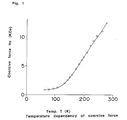
- Fig. 1 shows an example of temperature dependency of a coercive force of a MnBi magnetic powder.
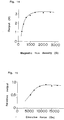
- Fig. 2 shows an example of an original magnetization curve and a hysteresis curve of a magnetic recording medium comprising the MnBi magnetic powder.
- Fig. 3 shows the results of the magnetic field stability test of a reproducing output of a magnetic card using the MnBi magnetic powder and a Co- ⁇ -Fe 2 O 3 magnetic powder.
- Fig. 4 shows the relationship between grinding time and particle size of the MnBi magnetic powder.
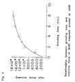
- Fig. 5 shows the relationship between grinding time and coercive force at 300K of the MnBi magnetic powder.
- Fig. 7 shows the relationship between grinding time and the magnetization at 300K of the MnBi magnetic powder.
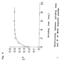
- Fig. 8 shows the relationship between grinding time and S* of the MnBi magnetic powder.
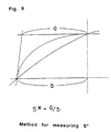
- Fig. 9 illustrates a method for measuring S*.
- Fig. 10 shows the results of X-ray diffraction analysis of the MnBi magnetic powder when it is maintained in a humid atmosphere.
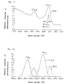
- Fig. 11 shows the spectrum of a photoelectron spectroscopic analysis of Mn.
- Fig. 12 shows the spectrum of a photoelectron spectroscopic analysis of Bi.
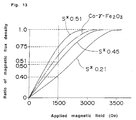
- Fig. 13 shows the relationship between magnetic flux density and magnetic field applied to a medium comprising the MnBi magnetic powder.
- Fig. 14 shows the relationship between the output and magnetic flux density of a medium comprising the MnBi magnetic powder.
- Fig. 15 shows the relationship between a function for preventing data alteration and the coercive force of a medium comprising the MnBi magnetic powder.
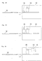
- Fig. 16 is an enlarged cross sectional view of an example of the magnetic card produced in the present invention.
- Fig. 17 is an enlarged cross sectional view of another example of the magnetic card produced in the present invention.
- Fig. 18 is an enlarged cross sectional view of a further example of the magnetic card produced in the present invention.
- Fig. 20 is an enlarged cross sectional view of yet a further example of the magnetic card produced in the present invention.
- Fig. 21 is an enlarged cross sectional view of a further example of the magnetic card produced in the present invention.
- Fig. 22 is an enlarged cross sectional view of an additional example of the magnetic card produced in the present invention.
- Fig. 23 is a schematic view of a reproducing apparatus according to an example of the present invention.
- Fig. 24 is a schematic view of a reproducing apparatus according to another example of the present invention.
- Fig. 25 is a schematic view of a reproducing apparatus according to a further example of the present invention.
- Fig. 26 is a plan view of a card form magnetic recording medium according to an example of the present invention.
- Fig. 27 is a plan view of a card form magnetic recording medium according to another example of the present invention.
- Fig. 1 showing the temperature dependency of the coercive force of an example of the MnBi magnetic powder
- its coercive force is as high as about 12,000 Oe at room temperature, whilst it decreases as the temperature decreases, and reaches 1500 Oe or less at 100K.
- the MnBi magnetic powder can be demagnetized by cooling it to a low temperature and after demagnetization it is easily magnetized at room temperature.
- Fig. 2 shows an original magnetization curve of a magnetic recording medium comprising the MnBi magnetic powder.
- the magnetic recording medium when it is demagnetized by cooling it at a low temperature, it can be magnetized easily by a small magnetic field of about 2000 Oe. However, once this magnetic recording medium is magnetized it has a high coercive force of about 14,000 Oe, and thereafter, data is hardly or not erased or rewritten.
- Fig. 3 shows the erasing characteristic of the magnetic card utilizing such magnetic recording medium.
- Fig. 3 indicates that a conventional magnetic card is almost completely demagnetized by the application of a magnetic filed of about 1000 Oe, so that data can be easily rewritten.
- the output decreases only by 30 % when a magnetic field of about 5000 Oe is applied, and about 50 % of the output remains when a magnetic field of about 8000 Oe is applied.
- the MnBi magnetic powder of the present invention may be prepared by forming an MnBi ingot by a powder metallurgy method, an arc furnace melting method, a high frequency melting method, or a melt quenching method and grinding the ingot.
- a powder metallurgy method an arc furnace melting method, a high frequency melting method, or a melt quenching method and grinding the ingot.
- the magnetic powder is produced by the steps of producing the ingot, grinding the ingot and stabilizing the ground metal as described below.
- the MnBi magnetic powder may be obtained by a method other than grinding.
- a Mn powder and a Bi powder both having 297 ⁇ m to 44 ⁇ m (50 to 300 mesh) sizes are well mixed, and pressed under pressure to obtain an ingot.
- the above mixing is preferably carried out in an inert atmosphere, while it may be carried out in an oxidizing atmosphere.
- the molar ratio of Mn to Bi is from 45:55 to 65:35 preferably.
- the number of moles of Mn is larger than that of Bi, an oxide or hydroxide of Mn is formed on the surface of the produced MnBi magnetic powder, so that the corrosion resistance of the MnBi magnetic powder is improved, and good quality powder is obtained.
- the molar amount of Mn is preferably larger than that of Bi.
- Mn powder and the Bi powder to be used herein those containing a smaller amount of impurities are preferably used, while they may contain other metal such as Ni, Al, Cu, Pt, Zn, Fe, etc. to adjust the magnetic properties.
- other metal such as Ni, Al, Cu, Pt, Zn, Fe, etc.
- an amount of other metal is from 0.6 to 5.0 atomic % based on the amount of MnBi, since the magnetic properties cannot be preferably controlled if the amount of other metal is less than 0.6 atomic %, whilst the crystalline structure of MnBi is destroyed so that the inherent properties of MnBi cannot be attained if the amount of other metal exceeds 5.0 atomic %.
- an already ground powder may be used, or flakes or bulks such as shot may be finely ground and used.
- the synthesis reaction takes place smoothly when the Mn powder and the Bi powder which are finely ground to 297 ⁇ m to 44 ⁇ m (50 to 300 mesh), since MnBi is formed by diffusion of Mn and Bi through contact interfaces between the powder particles. Since the reaction is greatly influenced by surface properties, it is preferred to remove oxidized coatings from the surfaces of the Mn and Bi powders.
- the surfaces of the Mn and Bi powders are beforehand treated by a conventional surface treating method employed in the powder metallurgy such as etching with, for example, an acid, or degreasing with a solvent, and so on.
- the Mn and Bi powders are mixed by any apparatus such as an automated mortar, a ball mill, and so on.
- the produced molded piece is sealed in a glass container or a metal container and the interior of the container is evacuated or replaced by an inert gas to prevent oxidation of MnBi during the heat treatment.
- an inert gas hydrogen, nitrogen or argon may be used. Among them nitrogen gas is most suitable in view of a cost.
- the sealed container including the molded piece is placed in an electric furnace and heated at a temperature of 260 to 271°C for 2 to 15 days.
- the heat treatment requires a longer time, and an amount of magnetization of the obtained ingot is lowered.
- the temperature is too high, Bi melts and flows so that an homogeneous ingot cannot be obtained. Then the heat treatment is carried out preferably at a temperature just below the melting point of Bi.
- the produced MnBi ingot is removed from the electric furnace and coarsely ground by, for example, the automated mortar to adjust to a particle size to 100 to 500 ⁇ m. Then the coarse particles are finely ground by wet grinding using the impact of balls with a ball mill, a planetary ball mill, etc., or dry grinding using impact caused by impinging particles against other particles or a wall of a vessel with a jet mill, etc.
- the average particle size of the obtained MnBi magnetic powder is in the range between 0.1 ⁇ m and 20 ⁇ m.
- the particle size can be controlled by adjusting the grinding conditions. When the average particle size is smaller than 0.1 ⁇ m, the saturation magnetization of the finally obtained magnetic powder is decreased. When the average particle size exceeds 20 ⁇ m, the coercive force of the magnetic powder does not reach a sufficient value and surface smoothness of the finally produced magnetic recording medium is lowered so that satisfactory recording cannot be made.
- the MnBi magnetic powder having a coercive force of from 3000 to 15,000 Oe at 300K and 50 to 1000 Oe at 80K when measured by applying a magnetic field of 16 KOe, and an amount of saturation magnetization of from 20 emu/g to 60 emu/g when measured at 300K by applying a magnetic field of 16 KOe is obtained.
- the above obtained MnBi magnetic powder is still chemically unstable. When it is maintained at a high temperature and high humidity for a long time it is corroded so that the saturation magnetization is deteriorated. Then a following treatment is carried out to stabilize the MnBi magnetic powder.
- the method comprising forming a coating of an oxide or hydroxide of Mn or Bi which is contained in the MnBi magnetic powder is to be noted.
- a method comprising forming an oxide coating utilizing oxygen will be explained.
- a step of forming the coating of the oxides of Mn and Bi on the surfaces of the MnBi magnetic powder comprises heating the MnBi magnetic powder in an oxygen-containing atmosphere at a temperature in the range of from 20 to 150°C.
- the oxides of Bi are formed at the same time as the formation of the oxides of Mn.
- the magnetic powder in which the oxides of Mn are preferentially formed and the magnetic powder in which the oxides of Bi and those of Mn are formed at the same time have no material difference of the saturation magnetization in the original state. However, they have very different corrosion resistance and the magnetic powder in which the oxides of Mn are preferentially formed has extremely good corrosion resistance.
- the preferential formation of the oxides of Mn, typically MnO x , near the particle surfaces of the magnetic powder can be clearly confirmed by the X-ray photoelectron spectroscopic analysis.
- the oxides of Mn are preferentially formed in the above heating step, the oxides of Bi are formed to some extent.
- a ratio of the oxides of Mn to those of Bi is preferably at least 2 in terms of an atomic ratio of Mn to Bi (Mn/Bi). When this ratio is less than 2, the oxides of Mn and Bi tend to form a local cell, so that the corrosion resistance is insufficient.
- the larger ratio of the oxides of Mn to those of Bi is more preferred in view of the corrosion resistance.
- the degree of oxidization should be increased. As a result, the original saturation magnetization tends to decrease.
- the ratio of the oxides of Mn to those of Bi is preferably not larger than about 50 in terms of the atomic ratio of Mn to Bi (Mn/Bi).
- the thickness of the oxide coating formed near the surface increases and then the corrosion resistance is improved, whilst the original saturation magnetization is decreased.
- the thickness of the coating is from 1 to 50 wt. % of the magnetic powder particles. Whilst it is difficult to measure the thickness of the oxide coating, the thickness of the oxide coating is preferably adjusted so that the saturation magnetization of the magnetic powder is from 20 to 60 emu/g at 300K. Since the magnetic powder having the saturation magnetization of smaller than 20 emu/g has a thick oxide coating, its corrosion resistance is good, whilst the saturation magnetization is too low so that the output of the magnetic recording medium comprising such magnetic powder is decreased. When the saturation magnetization is larger than 60 emu/g, the thickness of the oxide coating is too thin so that the corrosion resistance is insufficient.
- MnO x is converted to MnO 2 by heating the MnBi magnetic powder in an inert gas in a second step.
- MnO 2 is a stable oxide, and formed only by heating in an oxidizing atmosphere at a high temperature, usually 500°C or higher. Heating Mn in an oxidizing atmosphere at such a high temperature will considerably decrease the saturation magnetization of the magnetic power, and also cause sintering agglomeration of the magnetic powder.
- the temperature in the second heating step is preferably higher than that in the first heating step, and preferably from 200 to 400°C.
- the temperature in the second heating step is preferably higher than that in the first heating step, and preferably from 200 to 400°C.
- the temperature is lower than 200°C, the conversion to MnO 2 is insufficient, whilst when the temperature is higher than 400°C, MnBi tends to decompose to Mn and Bi.
- the inert gas nitrogen gas or argon gas is usually used, whilst the heating in vacuum may achieve the same effect.
- the peak area based on the 2p electrons of the Mn ion is at least two times larger than the peak area based on the 4f electrons of the Bi ion when the magnetic powder is analyzed by ESCA.
- the above described method is a basic method for forming the oxides of Mn on the particle surfaces of the MnBi magnetic powder to improve the corrosion resistance of the magnetic powder. It may be possible to from a hydroxide on the surfaces of the magnetic powder by heating the magnetic powder in an atmosphere containing a small amount of water or the oxides and hydroxide of Mn may be formed together.
- the original value of the saturation magnetization of the above treated magnetic powder is from 20 to 60 emu/g. After this magnetic powder is kept in an atmosphere of 60°C and 90 %RH for 7 days, a degree of deterioration is 40 % or less. Such excellent corrosion resistance is attributed to the prevention of decomposition of MnBi to Mn and Bi by water since the inherent deliquescence of MnBi is suppressed.
- the coating of the nitride may be formed by heating the magnetic powder in an atmosphere of nitrogen or ammonia which optionally contains hydrogen.
- the magnetic powder is heated in a carbon-containing atmosphere of carbon monoxide or methane which optionally contains hydrogen.
- a heating temperature is preferably from 300 to 400°C.
- the nitride or carbide of Mn and Bi can be deposited from the vapor phase by a CVD method or a pyrolysis method.
- the corrosion resistance is further improved by the formation of the nitride or carbide of Mn or Bi on the above oxide coating formed on the particle surfaces of the magnetic powder.
- the corrosion resistance may be improved by the formation of a coating of an inorganic compound of a metal such as Ti, Si, Al, Zr, Mg, Pb or P.
- a metal such as Ti, Si, Al, Zr, Mg, Pb or P.
- an oxide is preferred. Specific examples are titanium oxide, silicon oxide, aluminum oxide, zirconium oxide, magnesium oxide, lead oxide and so on.
- a mixed oxide or solid solution comprising two or more of these oxides, such as mullite, aluminum titanate, forsterite, cordierite, spinel and the like may be used.
- the oxides, mixed oxides and solid solutions may be used in a crystal state or an amorphous state without difference.
- a method used in the conventional surface modification of powder may be employed.
- liquid phase methods such as a sol-gel method, a precipitation method, a microcapsulation method, etc.
- vapor phase methods such as the CVD method, the pyrolysis method, etc.
- mechanochemical method may be used.
- the MnBi magnetic powder is dispersed in an organic solvent such as toluene, and an organometallic compound such as a titanate, a silane or a silazane is added and dissolved in the dispersion. Then, by the addition of a slight amount of water or water already adhered to the MnBi magnetic powder, the organo-metallic compound is hydrolyzed on the surfaces of the magnetic powder to absorb the hydrolyzed compound on the magnetic powder surfaces.
- an organic solvent such as toluene
- an organometallic compound such as a titanate, a silane or a silazane
- the magnetic powder is heated in a non-oxidizing gas atmosphere or an atmosphere containing a slight amount of oxygen, the organometallic compound absorbed on the magnetic powder surfaces is condensed through the liberation of water to form a coating of an oxide such as titanium oxide or silicon oxide.
- the corrosion resistance of the MnBi magnetic powder can be significantly improved by the formation of the oxides or hydroxides of Mn or Bi, the nitride or carbide of Mn and Bi, and further the inorganic compound of the metal such as Ti, Si, Al, Zr, Mg, Pb or P on the particle surfaces of the MnBi magnetic powder.
- the coating of the inorganic compound is formed preferably in an amount such that the weight of the inorganic compound is from 2 to 50 wt. % of the MnBi weight.
- the amount of the inorganic compound is too small, the corrosion resistance is unsatisfactory, whilst if it is too large, the saturation magnetization is decreased.
- the formation of the coating of the inorganic compound provides the magnetic powder having corrosion resistance and the magnetic properties in good balance.
- the above method produces the magnetic powder comprising MnBi, which has an average particle size of from 0.1 ⁇ m to 20 ⁇ m; a coercive force of from 3000 to 15,000 Oe at 300K and 50 to 1000 Oe at 80K when measured by applying a magnetic field of 16 KOe; and an amount of saturation magnetization of from 20 emu/g to 60 emu/g when measured at 300K by applying a magnetic field of 16 KOe.
- the magnetic powder treated by the above described method has excellent corrosion resistance, a degree of deterioration of the property is 40 % of less after being maintained in an atmosphere of 60°C and 90 %RH for 7 days.
- the content of Bi satisfies the following equation: Metal Bi/(MnBi + metal Bi) ⁇ 0.5 when the magnetic powder is analyzed by the X-ray diffraction.
- the magnetic powder of the present invention shows good corrosion resistance at high temperatures and high humidity and its saturation magnetization is hardly deteriorated, even when it is dipped in a corrosive solution such as an aqueous solution of sodium chloride or acetic acid.
- a magnetic recording medium comprising the above produced MnBi magnetic powder may be produced by a conventional method.
- the MnBi magnetic powder, a binder resin and an organic solvent are mixed and dispersed to prepare a magnetic paint, and the magnetic paint is coated on a substrate and dried to form a magnetic layer.
- binder resin any one of binder resins which are conventionally used in the magnetic recording medium may be used.
- a vinyl chloride-vinyl acetate copolymer, a polyvinyl butyral resin, a cellulose resin, a fluororesin, a polyurethane resin, an isocyanate compound, a radiation curable resin and so on can be used.
- the MnBi magnetic powder is easily corroded and decomposed when water is present. In particular, when water is acidic, the corrosion and decomposition are remarkable. Whilst the above binder resin is sufficient for uniformly dispersing the MnBi magnetic powder in the magnetic layer, it is preferred for the binder resin to include a basic functional group to further improve the stability of the magnetic powder against water.
- the inclusion of the basic functional group in the binder resin can further improve the corrosion resistance.
- the basic functional group imine, amine, amide, thiourea, thiazole, ammonium salt or phosphonium compound is preferred.
- the addition of a compound having a basic functional group is also effective.
- the basic functional group to be included in the additive compound imine, amine, amide, thiourea, thiazole, ammonium salt or phosphonium compound is preferred as in the case of the binder resin.
- Preferred examples of such compound are primary aliphatic amines such as methylamine, ethylamine, propylamine, isopropylamine, butylamine, amylamine, hexylamine, heptylamine, octylamine, nonylamine, decylamine, undecylamine, dodecylamine, tridedylamine, tetradecylamine, pentadecylamine, cetylamine, stearylamine, etc.; secondary aliphatic amines such as dimethylamine, diethylamine, dipropylamine, diisopropylamine, dibutylamine, diamylamine, etc.; tertiary aliphatic amines such as trimethylamine, triethylamine, tripropylamine, tributylamine, triamylamine, tridecylamine, etc.; unsaturated aliphatic amines; alicyclic
- the amount of the additive compound having the basic functional group increases, the effect on the improvement of the corrosion resistance increases. However, too much additive compound decreases the magnetic flux density of the magnetic layer.
- the amount of the additive compound is preferably from 1 to 15 wt. % based on the weight of the magnetic powder. To increase the corrosion resistance without significantly decreasing the magnetic flux density of the magnetic layer, the amount of the additive compound is preferably from 4 to 10 wt. %.
- a conventionally used additive such as a dispersant, a lubricant, an antistatic agent, etc. may be optionally added.
- a dispersant such as sodium tartrate
- a lubricant such as sodium tartrate
- an antistatic agent such as sodium sulfate
- the amount of the acidic lubricant which is generally used in the magnetic recording medium is made as small as possible in view of the corrosion resistance.
- the content of the magnetic powder is selected such that the volume ratio of the magnetic powder in the magnetic layer is from 5 to 60 %.
- this volume ratio is small, the output of the magnetic recording medium having such a magnetic layer is lowered and the corrosion resistance is decreased.
- the reason why the corrosion resistance is decreased when the volume ratio of the magnetic powder is small has not been clarified but it is assumed as follows:
- the volume ratio of the binder resin in the coated layer is too large, water is easily penetrated in the layer, so that the corrosion resistance decreases.
- the volume ratio of the magnetic powder is too large, the dispersibility of the magnetic powder is worsened so that the orientation of the magnetic powder is deteriorated, and at the same time, an effect of the binder resin for embedding the magnetic powder becomes insufficient, whereby the corrosion resistance is decreased.
- the volume ratio of the MnBi magnetic powder in the magnetic layer has an influence on the magnetic properties and recording characteristics as in the case of the conventional magnetic recording medium and further an influence on the corrosion resistance which is a specific problem found in the coated layer comprising this magnetic powder.
- the volume ratio of the magnetic powder is from 5 to 60 %.
- this volume ratio is from 10 to 50 %, the corrosion resistance is more effectively improved. Most preferably this volume ratio is from 20 to 45 %.
- the MnBi magnetic powder, the binder resin, the organic solvent and so on are mixed and dispersed to prepare the magnetic paint, and then the magnetic paint is coated on a substrate such as a polyester film by a suitable coating method and dried to form the magnetic layer, it is preferred to orientate the magnetic powder in a magnetic field in parallel with the plane of the magnetic layer.
- the intensity of the magnetic field is preferably from 500 to 3000 Oe.
- a magnetic recording medium having a coercive force of from 5000 to 16,000 Oe at 300K and 100 to 1500 Oe at 80K when measured by applying a magnetic field of 16 KOe, the magnetic flux density Bm of from 500 to 2500 G when measured at 300K by applying a magnetic field of 16 KOe, and the squareness Br/Bm in the longitudinal direction of from 0.60 to 0.95.
- the magnetic paint is coated on a substrate having an already coated releasing layer.
- a synthetic resin which has a low surface activity and used as a releasing agent in a tape, a seal or a sheet, for example, a silicone resin can be used.
- the thickness of the releasing layer is preferably from 0.1 to 2.0 ⁇ m.
- a water-repellent layer comprising a water-repellent resin is preferably provided between the releasing layer and the magnetic layer.
- the water-repellent resin a polyvinylidene chloride resin, an ethylene-vinyl alcohol copolymer, a fluororesin or vinylidene fluoride base resin, an acrylic resin and so on can be used.
- the thickness of the water-repellent layer is preferably from 0.5 to 10 ⁇ m. When the thickness is smaller than 0.5 ⁇ m sufficient water repellency is not obtained, whilst if it is too large, spacing loss increases, so that the output of the magnetic recording medium is decreased.
- the above produced magnetic recording medium is excellent in corrosion resistance and the decrease of the magnetic flux density is 50 % or less after being maintained in an atmosphere of 60°C and 90 %RH for 7 days.
- the decease of the magnetic flux density is 80 % or less.
- the magnetic flux density is at least 50 % of the saturated magnetic flux density at 300K.
- the MnBi magnetic powder of the present invention may be used in combination with other magnetic powders.
- the combined use of the magnetic powders can provide a magnetic recording medium having unique characteristics which are not found in the conventional magnetic recording media, by making the best use of the properties of the MnBi magnetic powder.
- the magnetic paint may be prepared in the same manner as when the MnBi magnetic powder alone is used.
- the dispersing method or the intensity of magnetic field for orientation may be selected according to the kinds and amounts of the magnetic powders to be mixed.
- the mixing ratio of the MnBi magnetic powder to the other magnetic powder is preferably from 1:9 to 7:3.
- the ratio of the former to the latter is larger than the above upper limit, the above advantages may not be achieved in comparison with the magnetic recording medium using the MnBi magnetic powder alone.
- this ratio is smaller than the above lower limit, one of the most important characteristics of the magnetic recording medium using the MnBi magnetic powder is that the data once recorded, cannot be easily erased or lost.
- a magnetic layer comprising the MnBi magnetic powder, and a magnetic powder comprising the gamma iron oxide magnetic powder, the cobalt-containing iron oxide magnetic powder, the barium ferrite magnetic powder, the strontium ferrite magnetic powder, or the metal magnetic powder comprising iron can be laminated.
- the advantages of the lamination of the magnetic layers are basically the same as those achieved by the use of the MnBi magnetic powder and the other magnetic powder in combination.
- the magnetic recording medium comprising the laminated magnetic layers is characterized in that two kinds of data, that is, data which can be rewritten and data which can be hardly rewritten once it is recorded, can be recorded in the single magnetic recording medium.
- the magnetic layer comprising the MnBi magnetic powder is formed in a stripe form.
- the magnetic layer comprising the gamma iron oxide magnetic powder, the cobalt-containing iron oxide magnetic powder, the barium ferrite magnetic powder, the strontium ferrite magnetic powder, or the metal magnetic powder comprising iron is then coated to cover the above stripe form magnetic layer.
- the data can be rewritten in a part of the magnetic recording medium having no magnetic layer comprising the MnBi magnetic powder, as in the conventional magnetic medium.
- the magnetic layer comprising the MnBi magnetic power and the magnetic layer comprising the other magnetic powder are laminated, the data can be easily written but can be hardly rewritten.
- Such a characteristic cannot be realized in the conventional magnetic recording media, and is firstly realized by the above structure of the magnetic recording medium by the use of the MnBi magnetic powder.
- a thickness of each magnetic layer is preferably from 2 to 20 ⁇ m, and a total thickness of the magnetic layers is preferably from 3 to 30 ⁇ m in the case of the magnetic card.
- these thicknesses are too thin, the output becomes too low, so that the reliability of the card deteriorates.
- they are too thick, it is difficult to record the data uniformly over the whole magnetic recording layers, so that the error rate increases in the reproduction of the data.
- the magnetic paint is coated on a substrate film having an already coated releasing layer while orientating the magnetic powder in the magnetic field and dried.
- an adhesive layer is coated on the magnetic layer.
- a fusion type adhesive such as a urethane resin, an acrylic resin, etc. is preferably used, while other adhesive such as an isocyanate curing type adhesive, a UV light curing type adhesive, etc. may be used.
- the water-repellent layer comprising the water-repellent resin is inserted between the releasing layer and the magnetic layer.
- the general structure of the magnetic recording medium comprises the substrate film, the releasing layer, the water-repellent layer, the magnetic layer, and the adhesive layer.
- any measure that is used in the magnetic card such as the formation of a shielding layer such as a coloring layer between the releasing layer and the magnetic layer can be combined.
- the above produced magnetic recording medium in the form of a tape is slit in a determined width and a strip form recording medium is laminated on the magnetic card substrate by contacting the adhesive layer to the substrate and temporarily adhered on the surface of the substrate, for example, by pressing the strip by a heat roller, followed by removal of the substrate film to obtain the magnetic card.
- the magnetic recording medium is heat pressed by, for example, a press plate so that the adhesive layer, the magnetic layer and the releasing layer are embedded in the substrate, and then cut out in card form.
- the produced magnetic recording medium is initialized and then recorded and reproduced.
- the magnetic recording medium comprising the MnBi magnetic powder is initialized by utilizing the properties of the MnBi magnetic powder which has a large coercive force at room temperature whilst the coercive force is greatly decreased when it is cooled to a low temperature of about 100K or lower.
- the initialization of the magnetic recording medium comprising the MnBi magnetic powder comprises applying an alternating magnetic field of 300 to 3000 Oe to the magnetic recording medium at a temperature of about 100K or lower to demagnetize the medium.
- This initialization can be carried out by traveling a magnetic tape when the medium is in the form of a tape, or in a batchwise manner with the tape wound around a reel.
- the magnetic recording medium can be initialized after it is processed in the form of the magnetic card.
- the method for recording the data is not different from the conventional recording method.
- the data in the case of the magnetic card, the data can be recorded using an encoder or a magnetic card reader-writer. Different from the other magnetic recording media, once the data is recorded on the magnetic recording medium comprising the MnBi magnetic powder, they can be hardly erased or rewritten.
- the recording of data is repeated at least twice.
- fixed data (A) which cannot be rewritten are recorded using a writer.
- the same data (A) are recorded in the MnBi magnetic powder and the magnetic powder other than the MnBi magnetic powder.
- the intensity of the recording magnetic field depends on the coercive force of the other magnetic powder to be used in combination with the MnBi magnetic powder.
- the intensity of the recording magnetic field is preferably as high as possible in a range in which the other magnetic powder is not demagnetized. This is based on a phenomenon that the coercive force of the magnetic recording medium is larger as the intensity of the recording magnetic field is higher, which phenomenon is specific to the magnetic recording medium comprising the MnBi magnetic powder.
- the unrewritable fixed data (A) and the rewritable data (B) are recorded at different recording densities.
- the recording density of the rewritable data is 3 to 100 times larger than that of the fixed data, since, in general, the rewritable data require a larger recording capacity than the fixed data.
- the recording densities should be differentiated so as to separately reproduce the two kinds of the data using, for example, a filter which prevents mutual interference of the magnetic fields from the signals of the data (A) and (B). In view of the degree of separation, a larger difference between two recording densities is better. To increase the amount of the data (A), the difference is 100 times or less.
- the data (A) are first written in all the magnetic layers, and the data (B) are overwritten, whereby the data recorded in the other magnetic powder or the magnetic layer comprising the other magnetic powder are rewritten. But, since the MnBi magnetic powder or the magnetic layer comprising the MnBi magnetic powder has a large coercive force of 10,000 Oe or larger at room temperature, the data once recorded therein is not rewritten by the data (B) which is to be recorded later, and the already recorded fixed data (A) remains.
- the direct magnetic field When the direct magnetic field is applied after the unrewritable data (A) is recorded, the data (A) is further stabilized against the external magnetic field.
- the direct magnetic field has the intensity of 3000 to 10,000 Oe preferably.
- the data (B) is recorded as described above, whereby the fixed data (A) and the rewritable data (B) are recorded in the same track.
- the magnetic layer comprising the MnBi magnetic powder and the magnetic layer comprising the other magnetic powder are laminated, the data which can be rewritten and the data which can be hardly rewritten once recorded can be recorded in the single magnetic recording medium.
- the magnetic layer comprising the MnBi magnetic powder is formed in a stripe form. Then, the magnetic layer comprising the gamma iron oxide magnetic powder, the cobalt-containing iron oxide magnetic powder, the barium ferrite magnetic powder, the strontium ferrite magnetic powder, or the metal magnetic powder comprising iron is coated to cover the above magnetic layer. Then, the data, which is recorded in the area where the magnetic layer comprising the MnBi magnetic powder and the magnetic layer comprising the other magnetic powder are laminated, can be hardly rewritten, while the data in the area where the magnetic layers are not laminated can be rewritten as in the case of the conventional magnetic recording medium.
- the unrewritable fixed data (A) is recorded in the area where the magnetic layer comprising the MnBi magnetic powder and the magnetic layer comprising the other magnetic powder are laminated by the conventional method. If it is attempted to rewrite the recorded data (A) by the data (B) for the purpose of altering the data, two signals from the data (A) and (B) are mixed up in the reproduction step so that the data is destroyed, since the data recorded in the magnetic layer comprising the MnBi magnetic powder cannot be rewritten. Then the data cannot be reproduced by a conventional reading apparatus.
- rewritable data (C) is recorded in the magnetic layer comprising the magnetic powder other than the MnBi magnetic powder.
- the data (C) can be rewritten at any time in use as in the case of the conventional magnetic medium.
- the present invention has been explained by making reference to the magnetic layer comprising the MnBi magnetic powder and the other magnetic powder in combination, and the laminated magnetic layers comprising these magnetic powders respectively.
- These magnetic layers may be combined in various ways.
- the laminated magnetic layers are formed on one surface of the card, while the conventional magnetic layer comprising the iron oxide magnetic powder or the barium ferrite magnetic powder is formed on the other surface of the card.
- the data reproduction can be carried out by substantially the same reproduction method as that of the conventional magnetic recording medium.
- the magnetic card can be read using the magnetic card reader.
- two sets of data (A) and (B) having different recording densities are separately reproduced by passing the signals which are read by the magnetic head through a band pass filter, as will be explained in detail in the Examples.
- the band width of the band pass filter is preferably adjusted in a range between +100 % and -50 % from the frequency corresponding to the recording density to be reproduced.
- the present invention has been explained by making reference to the case where the invention is applied to a magnetic card.
- the present invention in which the hardly rewritable data and the easily rewritable data as in the case of the conventional magnetic recording media are multiply recorded or recorded in combination in a single magnetic recording medium, can be used in any magnetic recording medium such as a magnetic tape or a floppy disc, in addition to the magnetic card.
- the magnetic recording medium such as the magnetic card comprising the MnBi magnetic powder is characterized in that the data, once recorded, cannot be easily erased at room temperature, that is, the data, once recorded, cannot be easily altered, but the recorded data can be easily read in the same manner as used with a conventional magnetic card. It is thought that such data is copied on a normal magnetic card and the copied card is used as if it were a genuine card.
- a method and apparatus for reproducing only the genuine data which is recorded using the MnBi magnetic powder are required.
- a direct or alternating magnetic filed having an intensity smaller than the coercive force of the magnetic layer is applied on the magnetic layer using, for example, a permanent magnet or a magnetic head for applying the magnetic field.
- the intensity of such a magnetic field is smaller than the coercive force of the magnetic layer comprising the MnBi magnetic powder and larger than the coercive force of the magnetic layer comprising the conventional magnetic powder.
- the data of the copied card is almost erased by the application of a magnetic field of 500 to 1000 Oe.
- the intensity of the applied magnetic field is preferably from 500 to 5000 Oe.
- the identification information can be added by the formation of a cut part or a small hole in a part of the magnetic card to differentiate the shape of the card from a normal magnetic card. Then the cut part or the small hole is detected optically or mechanically when the magnetic card is inserted in the apparatus and the card having the cut part or the small hole is allowed to be inserted, while the magnetic card having neither the cut part nor the small hole is ejected from the apparatus.
- a mark is printed on the card surface with an ink containing a fluorescent substance which can be excited by IR or UV light, and the magnetic card is identified by exciting the fluorescent substance by the IR or UV light, and detecting the fluorescence emitted from the identification mark.
- the synthesis method of the MnBi magnetic powder comprises the step of producing an MnBi ingot, the step of preparing a MnBi magnetic powder by grinding the ingot, and a step of heat treating the ground MnBi magnetic powder.
- Flakes of Mn (manufactured by FURU-UCHI CHEMICAL Co., Ltd. Purity, 99.9 %), and Bi shot (manufactured by FURU-UCHI CHEMICAL Co., Ltd. Purity, 99.9 %) were ground in a mortar and Mn powder and Bi powder were separately sieved in a range between 2 mm (10 mesh) and 500 mesh to obtain Mn and Bi powders having different particle sizes.
- the Mn and Bi powders were weighed so that the molar ratio of Mn to Bi was from 25:75 to 75:25 and mixed thoroughly in a ball mill.
- the molded article was contained in an aluminum container which could be top closed. After evacuating the container, nitrogen gas of 50.6 kPa (0.5 atm) was introduced in the container. Then the container was placed in an electric furnace and heated at a temperature of 250 to 300°C for 1 to 30 days. After heat treatment, the molded article was removed into air and lightly ground in a mortar and its magnetic properties were measured.
- the coercive force when the maximum magnetic field of 16 KOe was applied and the magnetization at 16 KOe were measured.
- the coercive force did not depend on the processing conditions significantly and was from 500 Oe to 1000 Oe, while the amount of magnetization greatly varied with the processing conditions. Then from the amounts of magnetization and the proportions, of synthesized MnBi in the ingots were evaluated and the optimum conditions for the production of MnBi were determined from those proportions.
- MnBi ingots were produced by changing the particle sizes of the Mn and Bi powders as the raw materials, mixing ratios of the Mn and Bi powders, the molding pressure for pressing the mixture of the Mn and Bi powders, and the heating temperature and time of the molded articles as shown in Table 1 and the magnetization of the MnBi ingots were measured. The results are shown in Table 1. Ex. No. Particle size of Mn and Bi powders (mesh) Molar ratio of Mn/Bi Synthesis pressure (t/cm 2 ) Treating temp.
- the particle sizes of the raw material Mn and Bi powders influence the magnetization of the ingots obtained by heat treatment.
- the surface areas of the powders are large.
- a ratio of the oxide coating formed on the particle surfaces increases so that the reaction is interfered.
- the particle sizes are too large the surface area is too small.
- the contact area for effecting the diffusion of Mn and Bi is decreased so that the reaction rate is lowered, whereby the magnetization of the obtained ingot is small.
- the optimum particle size of the Mn and Bi powders as the raw materials is from 297 ⁇ m to ⁇ 44 ⁇ m (50 mesh to 300 mesh).
- the heat treating temperature of the molded article is very important to attain high magnetization and it is preferred to carry out the heat treatment at a temperature just below the melting point of metal Bi.
- a temperature just below the melting point of metal Bi When the molded article is heated at a temperature higher than the melting point of Bi, only Bi is molten and agglomerated. Therefore the reactivity as MnBi is greatly decreased.
- this heat treatment temperature is too low, the diffusion rates of Mn and Bi are lowered, so that a very long time is required for the heat treatment to achieve a high magnetization.
- the heat treatment is preferably carried out at a temperature of 260 to 271°C which is just below the melting point of Bi.
- the obtained MnBi ingot was coarsely ground using a mortar in an inert (nitrogen) atmosphere in a glove box and further finely ground using a ball mill and a jet mill.
- As the ingot one prepared in Example 3 was used.
- ball milling a planetary ball mill was used, and the coarse powder was milled in one of various solvents in an amount of 100 wt. parts per 10 wt. parts of MnBi.
- zirconia balls were used and the powder was ground under the same conditions.
- the powder was ground with the zirconia balls under gentle milling conditions at a low rotation rate (100 rpm) as the first milling step, and then ground with the zirconia balls having a smaller diameter than those used in the first step and a high rotation rate (150 rpm) as the second milling step. Then the two kinds of the powders were compared.
- the MnBi fine powder can be produced by either ball milling or jet milling.
- a non-polar solvent such as toluene or xylene
- the decrease of the amount of magnetization caused by milling is small.
- the diameter of the balls is decreased as the grinding proceeds, powder having uniform particle size distribution is obtained.
- Example 35 of Table 2 in which, whilst the particle size was small, high saturation magnetization was attained, since the formation of the very fine particles which cause the decrease of saturation magnetization was suppressed.
- Figs. 4 to 7 show the particle sizes, coercive forces at 300K and 80K, and the saturation magnetization at 300K obtained in Example 35 in which the first milling was carried out for 2 hours, and thereafter, the second milling was carried out in varying time periods.
- Fig. 8 shows the results of the measurement of change of S* by grinding.
- the S* is a parameter obtained from a slope of the demagnetization curve of the hysteresis curve. The larger value of S* indicates a narrower distribution of the coercive force. This measurement was done at 300K by applying a magnetic field of 16 kOe.
- the magnetic recording medium comprising such magnetic powder has the further improved function of preventing data alteration.
- the magnetization considerably decreases.
- the coercive force at 300K is preferably from 3000 Oe to 15,000 Oe.
- the magnetic powder can be used in the magnetic recording medium of the present invention when it satisfies the above requirements at the same time.
- the above method produces the MnBi magnetic powder having the desired shape and properties.
- the MnBi magnetic powder in this state is unstable and corroded by the presence of water so that the amount of magnetization decreases. Then the MnBi magnetic powder is stabilized by the following heat treatment.
- the MnBi magnetic powder was removed in the state dipped in toluene, and charged in a heat treating vessel followed by drying in vacuo at room temperature (25°C) for about 2 hours.
- the powder was heat treated at a temperature varying from 20°C to 150°C as the first step.
- the heating time was long when the heat treating temperature was low, whilst it was short when the heat treating temperature was high.
- the heating time was in the range between 0.5 hour to 24 hours.
- nitrogen gas containing 1000 ppm of oxygen was used as a heat treating atmosphere.
- the oxygen-containing gas was evacuated from the vessel, and nitrogen gas or argon gas was introduced at a pressure of about 40 Pa (0.3 torr.) in the vessel so that the pressure did not exceed 133.3 Pa (1 torr.) when heated.
- the magnetic powder was heat treated with varying the temperature between 150°C and 450°C.
- the heating time was preferably adjusted according to the heating temperature as in the first step. In this Example, the heating time was constant at 2 hours.
- the degree of decrease of the magnetization and the metal Bi content were measured as follows:
- a magnetic powder was maintained in a glass dish in an atmosphere of 60°C and 90 %RH for 7 days. From a change rate of the saturation magnetization after this period from that before this period, the degree of decrease of the magnetization was obtained.
- Metal Bi content (Peak area of metal Bi)/(Peak area of MnBi + Peak area of metal Bi)
- Fig. 10 shows an example of an X-ray diffraction pattern from which the metal Bi content was calculated after the MnBi magnetic powder was maintained in an atmosphere of 60°C and 90 %RH for 7 days.
- 2nd step heat treatment Amount of magnetization (emu/g) Coercive force (Oe) Decrease of amount of magnetization (%)
- Metal Bi content 40 - - - N 2 gas, 350°C x 2 hrs. 52.8 8300 35 0.55 41 O 2 /N 2 mixed gas, 30°C x 24 hrs. N 2 gas, 350°C x 2 hrs. 50.4 9500 8 0.06 42 O 2 /N 2 mixed gas, 40°C x 15 hrs.
- N 2 gas 350°C x 2 hrs. 50.2 9600 6 0.04 43 O 2 /N 2 mixed gas, 60°C x 8 hrs. N 2 gas, 350°C x 2 hrs. 49.1 9600 7 0.04 44 O 2 /N 2 mixed gas, 80°C x 3 hrs. N 2 gas, 350°C x 2 hrs. 46.3 9800 10 0.10 45 O 2 /N 2 mixed gas, 100°C x 1 hr. N 2 gas, 350°C x 2 hrs. 43.5 10100 12 0.15 46 O 2 /N 2 mixed gas, 200°C x 0.5 hrs. N 2 gas, 350°C x 2 hrs.
- the ratio of the Mn oxides to the Bi oxides formed near the particle surfaces of the MnBi magnetic powder was measured by photoelectron spectroscopy.
- metal Mg was used as a source.
- Figs. 11 and 12 show the spectra of 2p electrons of Mn and 4f electrons of Bi, respectively.
- the peaks assigned to metal Mn and metal Bi of MnBi were observed in addition to the peaks assigned to the Mn oxides and the Bi oxides. These peaks were separated using a computer, and peak areas for the Mn oxides and the Bi oxides were calculated.
- the ratio of the Mn oxides to the Bi oxides was calculated from the ratio of the peak area of the 2p3/2 electrons of the Mn oxides to that of the 4f7/2 electrons of the Bi oxides.
- each of the Mn oxides and the Bi oxides contain several oxides having different valencies. Then, using the measured peaks of standard samples of Mn and Bi oxides having known valencies, the peaks of Figs. 11 and 12 were separated by computer fitting. From the separated peak areas, the atomic ratio x of oxygen atoms to Mn or Bi atoms when the oxides were expressed by the composition formulae MnO x and BiO x , and a content of MnO x in which x was 2 were calculated.
- Ratio of Mn oxides to Bi oxides (Mn/Bi) Atomic ratio of oxygen to Mn (x) Atomic ratio of oxygen to Bi (x) Content of MnO 2 in MnO x (%) 40 1.5 1.2 1.5 52 41 5.8 1.7 1.5 73 42 6.2 1.7 1.5 75 43 10.5 1.8 1.6 80 47 4.4 1.5 1.5 53 48 5.1 1.5 1.5 62 54 5.8 1.8 1.6 78 55 11.0 1.7 1.5 76 C. 1 1.1 1.3 1.5 30
- the Mn oxides having a specific structure are preferentially formed.
- the ratio of the Mn oxides to the Bi oxides is at least 2 in terms of the atomic ratio of Mn to Bi (Mn/Bi)
- the magnetic powder has excellent corrosion resistance.
- MnO x in which x is 2, is present in an amount of 50 atomic % or more of the whole Mn oxides, the magnetic powder has better corrosion resistance.
- MnBi magnetic powder on particle surfaces of which an oxide coating is formed As a MnBi magnetic powder on particle surfaces of which an oxide coating is formed, a MnBi magnetic powder having a coating of TiO 2 or SiO 2 will be explained.
- MnBi magnetic powder stabilization treated in Example 41
- Tetraisopropyl titanate 3 wt. parts
- Toluene 1125 wt. parts
- tetraisopropyl titanate was hydrolyzed by water in the air or present on the particle surfaces of the MnBi magnetic powder and absorbed on the particle surfaces of the MnBi powder.
- the MnBi magnetic powder carrying the absorbed tetraisopropyl titanate was heated in a nitrogen gas at 350°C for 2 hours, whereby tetraisopropyl titanate was condensed, liberating water to form a dense TiO 2 coating.
- Example 56 In the same manner as in Example 56 except that the magnetic powder of Comparative Example 1 which was not subjected to the stabilization treatment was used as the MnBi magnetic powder in place of the magnetic powder of Example 41 which was subjected to the stabilization treatment, the TiO 2 coating was formed on the particle surfaces of the MnBi magnetic powder.
- Example 58 In the same manner as in Example 58 except that the magnetic powder of Comparative Example 1 which was not subjected to the stabilization treatment was used as the MnBi magnetic powder in place of the magnetic powder of Example 41 which was subjected to the stabilization treatment, the SiO 2 coating was formed on the particle surfaces of the MnBi magnetic powder.
- the following components were thoroughly dispersed in a ball mill to obtain a magnetic paint.
- the magnetic powder the heat treated MnBi magnetic powder of Example 41 was used. This magnetic powder had an average particle size of 2.5 ⁇ m, a coercive force of 9500 Oe and saturation magnetization of 50.4 emu/g.
- a magnetic paint having the following composition was coated on a PET film having a thickness of 30 ⁇ m on which a releasing layer was formed, to a dry thickness of 15 ⁇ m, whilst applying a magnetic field of 1500 Oe in the longitudinal direction: MnBi magnetic powder 100 wt. parts MPR-TAO (an amine-modified vinyl chloride-vinyl acetate copolymer manufactured by NISSHIN CHEMICAL Co., Ltd.) 25 wt. parts Cyclohexanone 50 wt. parts Toluene 50 wt. parts
- Example 60 In the same manner as in Example 60 except that ESLEC P (an amine-modified styrene-acrylate copolymer manufactured by SEKISUI CHEMICAL Co., Ltd.) in place of MPR-TAO, a magnetic paint was prepared and a magnetic layer was formed.
- ESLEC P an amine-modified styrene-acrylate copolymer manufactured by SEKISUI CHEMICAL Co., Ltd.
- Example 60 In the same manner as in Example 60 except that 1 (one) wt. part of stearylamine was further added as an additive, a magnetic paint was prepared and a magnetic layer was formed.
- Example 60 In the same manner as in Example 60 except that 6 wt. parts of stearylamine was further added as an additive, a magnetic paint was prepared and a magnetic layer was formed.
- Example 60 In the same manner as in Example 60 except that VAGH (a vinyl chloride-vinyl acetate copolymer manufactured by UCC) was used in the same amount in place of MPR-TAO, and 6 wt. parts of stearylamine was further added as an additive, a magnetic paint was prepared and a magnetic layer was formed.
- VAGH a vinyl chloride-vinyl acetate copolymer manufactured by UCC
- Example 60 In the same manner as in Example 60 except that MR-110 (a sulfonic acid-modified styrene-acrylate copolymer manufactured by NIPPON ZEON) was used in the same amount in place of MPR-TAO, a magnetic paint was prepared and a magnetic layer was formed.
- MR-110 a sulfonic acid-modified styrene-acrylate copolymer manufactured by NIPPON ZEON
- Example 60 In the same manner as in Example 60 except that VAGH (a vinyl chloride-vinyl acetate copolymer manufactured by UCC) was used in the same amount in place of MPR-TAO, a magnetic paint was prepared and a magnetic layer was formed.
- VAGH a vinyl chloride-vinyl acetate copolymer manufactured by UCC
- the oxides of Mn are mainly formed on the particle surfaces of the MnBi magnetic powder.
- the oxides of Mn are basic.
- the functional group of the binder resin When the binder resin is absorbed on the particle surfaces of the magnetic powder, the functional group of the binder resin generally face the magnetic powder. If the functional group of the binder resin is acidic, an acid-base reaction takes place on the particle surface of the magnetic powder, whereby the decomposition of MnBi to Mn and Bi is accelerated. When water is present, the property of the functional group as an acid is strengthened, so that the decomposition is further accelerated and the magnetization is decreased.
- the functional group of the resin or the additive is basic, the decomposition of MnBi to Mn and Bi does not occur on the particle surface of the magnetic powder when the binder resin or the additive is absorbed with the functional group facing the particle surface, since the functional group is basic. Accordingly, in this case, the functional group is absorbed without damaging the MnBi magnetic powder.
- the main chain such as the alkylene group functions to prevent the reaction of the magnetic powder with water and so on which migrates from outside, whereby the corrosion resistance may be improved.
- Example 60 In the same manner as in Example 60 except, in place of the MnBi magnetic powder of Example 60, there was used a magnetic powder having different S* which was prepared by grinding the MnBi ingot shown in Fig. 8 in the first step and then grinding it in the second step for a grinding time of 0 hour (S*: 0.21), 1 (one) hour (S*: 0.45) or 4 hours (S*: 0.51), and further subjecting the powder to the stabilization treatment under the same conditions as in Example 41, a magnetic layer was formed.
- the data could be reproduced normally from the magnetic layer comprising the cobalt-containing ⁇ -Fe 2 O 3 magnetic powder or the MnBi magnetic powder in which the magnetic flux density was 50 % or more of the saturated magnetic flux density in Fig. 13.
- the reason why the data can be normally reproduced from the magnetic recording medium in which the magnetic flux density when the magnetic field of 1500 Oe is applied, is 50 % or more of the saturated magnetic flux density is assumed as follows:
- the magnetic flux density is 50 % or more, the output sufficient for reading is achieved. But, when it is less than 50 %, the magnetic flux density is too low and the output decreases. Further, as shown in Fig. 13, with the recording medium in which the slope of the original magnetization curve is not steep, the recording magnetization in the magnetic layer is destabilized, so that the read error tends to occur.
- the magnetic recording medium comprising the MnBi magnetic powder
- the magnetic recording medium when the original magnetization curve after demagnetization has a steeper slope, the magnetic recording medium can be recorded to saturation at a lower current, and that the data can be read without the read error from the magnetic recording medium in which the magnetic flux density, when the magnetic field of 1500 Oe is applied, is 50 % or more of the saturated magnetic flux density , when they are recorded and reproduced by the card reader-writer.
- a water-repellent layer comprising a water-repellent resin
- the corrosion resistance and acid resistance are further improved.
- the water-repellent layer is formed on the magnetic card, it is provided between the releasing layer and the magnetic layer.
- a paint having the following composition was coated on a PET film having a releasing layer of an acrylic acid resin thereon, to a dry thickness of 2.5 ⁇ m to form a water-repellent layer: SARAN RESIN F216 (vinylidene chloride resin manufactured by ASAHI CHEMICAL Co., Ltd.) 100 wt. parts Tetrahydrofuran 200 wt. parts Toluene 100 wt. parts
- the magnetic layer of the obtained magnetic tape was laminated on a polyvinyl chloride substrate for a magnetic card having a thickness of 0.76 mm, and pressed by a heated roll to adhere the tape to the substrate. After adhesion, the PET film was peeled off, and heat pressed by a press plate to embed the magnetic layer in the polyvinyl chloride substrate, followed by cutting to obtain a magnetic card.
- Example 68 In the same manner as in Example 68 except that EVAL RESIN F216 (ethylene-vinyl alcohol copolymer manufactured by KURARAY) was used in the same amount in place of SARAN RESIN F216, a water-repellent paint was prepared and a magnetic card was produced.
- EVAL RESIN F216 ethylene-vinyl alcohol copolymer manufactured by KURARAY
- Example 68 In the same manner as in Example 68 except that another water repellent layer was formed on the magnetic layer, a magnetic card was produced. That is, on the releasing layer, the water-repellent layer was formed, and on this water-repellent layer, the magnetic layer was formed. Then, another water-repellent layer was formed on the magnetic layer so as to sandwich the magnetic layer between the water-repellent layers.
- Example 68 In the same manner as in Example 68 except that no water-repellent layer was formed between the releasing layer and the magnetic layer, a magnetic card was produced.
- the corrosion resistance was measured as follows:
- the magnetic layer was cut out, and its magnetic flux density Bm (original value) was measured by applying a magnetic field of 16 kOe at 300K. Then, the card was maintained in an atmosphere of 60°C and 90 %RH for 7 days, and thereafter, a part of the magnetic tape having the same area as above was cut out, and its magnetic flux density was measured by applying a magnetic field of 16 kOe at 300K. The corrosion resistance was evaluated from the degree of decrease of the magnetic flux density in comparison to the original value.
- the acid resistance was evaluated by measuring the degree of decrease of the magnetic flux density by dipping a part of the magnetic tape in a 5 % aqueous solution of acetic acid at room temperature (25°C) for one day.
- the magnetic card having the water-repellent layer had the slightly better corrosion resistance than one having no water-repellent card (Comparative Example 7).
- the magnetic flux density of the magnetic card having no water-repellent layer decreased by 89.2 %, while that of the magnetic cards having the water-repellent layer between the releasing layer and the magnetic layer (Examples 68 and 69) decreased only by 2 to 6 %, and the acid resistance was significantly improved.
- the acid resistance was more improved in the magnetic card having the water-repellent layers which sandwiched the magnetic layer (Example 70) because the water-repellent layers prevented the migration of water into the magnetic layer from outside.
- those produced by changing the grinding time and having different properties as shown in Figs. 4-8 were used. That is, those magnetic powders were produced from the MnBi ingot produced by the method of Example 4, and ground by the two-step grinding method of Example 35. In addition, the magnetic powders were stabilized by heat treatment by the method of Example 41 after grinding.
- the magnetic paint was prepared by the same method as described in Example 64 except that a weight ratio of the magnetic powder to the binder resin was changed, and then the magnetic layer having the different weight ratio of the magnetic powder in the layer was produced.
- the weight ratio was deduced from a ratio of the measured magnetic flux density of each magnetic layer to the magnetic flux density of the magnetic layer consisting of 100 % of the magnetic powder which was calculated from the saturation magnetization of the magnetic powder.
- the magnetic card was produced by substantially the same method as that described in Example 68. The production method is briefly repeated here.
- the film on which the magnetic layer was coated by the method of Example 64 was slit in a width of 6 mm to prepare a magnetic tape. Then, the magnetic layer of the magnetic tape was laminated on the polyvinyl chloride substrate of the magnetic card having a thickness of 0.76 mm and pressed by a heated roll to adhere the tape to the substrate. After adhesion, the PET film was peeled off and heat pressed by a press plate to embed the magnetic layer in the polyvinyl chloride substrate, followed by cutting to obtain a magnetic card.
- the magnetic card was cooled by dipping it in liquid nitrogen. Thereafter, it was quickly initialized by the application of the alternating magnetic field of 1000 Oe.
- Table 8 includes the results of the evaluation of the magnetic layers formed from various MnBi magnetic powders, and Table 9 includes the results of the evaluation of the magnetic cards produced using the various MnBi magnetic powders.
- the coercive force Hc at 300K and 80K, the magnetic flux density Bm at 300K, the squareness Br/Bm, and the degree of decrease of the magnetic flux density after maintaining the magnetic layer in an atmosphere of 60°C and 90 %RH were measured.
- a reproducing output at 210 FCl and a resolution were measured.
- the reproducing output is influenced by the magnetic flux density at 300K, and the resolution and the function of preventing rewriting are influenced by the coercive force at 300K.
- Fig. 14 shows the relationship between the magnetic flux density and the reproducing output at 210 FCl of the magnetic cards the magnetic flux density of which were changed by varying the volume ratio of the magnetic powder with changing the coercive force from 10,000 Oe to 15,000 Oe at 300K.
- Fig. 15 shows the relationship between the function of rewriting of data and the coercive force of the magnetic cards, the coercive force of which were changed while changing the magnetic flux density from 1200 G to 1800 G at 300K.
- the magnetic layers having a coercive force of 5000 Oe or less at 300K have the low resolution of 80 % or less.
- the magnetic recording media having the coercive force of 5000 Oe or less do not have the property characteristic to the magnetic recording medium of the present invention that the data, once recorded, cannot be rewritten.
- the magnetic layer having the coercive force of 1500 Oe at 80K since the demagnetization property at low temperature is insufficient, the recording at room temperature is insufficient, so that high output may not be achieved. In particular, since the output at high recording density, that is, at 420 FCl is lowered, the resolution is decreased. In addition, with respect to the output at 210 FCl, as the magnetic flux density increases, the output increases. When the magnetic flux density is lower than 500 G, a sufficiently high output cannot be obtained.
- the squareness has a close relationship with the resolution. When the squareness is 0.60 or less, the resolution is greatly deteriorated.
- the volume ratio of the magnetic powder in the magnetic layer should be optimized. When this volume ratio is from 5 to 60 %, the magnetic layer and the magnetic card having good properties as a whole can be produced.
- the function of preventing rewriting has a close relationship with the coercive force at 300K.
- the coercive force is 5000 Oe or larger, the function of preventing rewriting is well achieved.
- the volume ratio of the magnetic powder, the coercive forces at 300K and 80K, the magnetic flux density at 300K and the squareness in the longitudinal direction should be selected in good balance to provide the magnetic recording medium which satisfies the following properties at the same time:
- the magnetic recording medium comprising the MnBi magnetic powder is characterized in that the once recorded data cannot be easily rewritten at room temperature.
- this characteristic is utilized in combination with other magnetic recording medium, a magnetic recording medium having a novel property which is not found in the conventional magnetic media can be obtained.
- the magnetic card In the case of a magnetic card, two magnetic layers one of which comprises the MnBi magnetic powder and the other of which comprises the conventional magnetic powder for magnetic recording such as cobalt-containing ⁇ -Fe 2 O 3 are formed at different positions on a card, the magnetic card has two kinds of data, that is, fixed data which cannot be rewritten and data which can be freely rewritten by a user.
- the unrewritable fixed data and the rewritable data can be recorded in the same track.
- the magnetic card has very high security.
- the magnetic layer comprising the MnBi magnetic powder and the magnetic layer comprising the conventional magnetic powder such as cobalt-containing ⁇ -Fe 2 O 3 are formed at different positions on the surface of the magnetic card, they are formed by coating the MnBi magnetic paint and the magnetic paint for the conventional magnetic recording medium at different positions.
- the magnetic layer comprising the MnBi magnetic powder and the magnetic layer comprising the conventional magnetic powder such as cobalt-containing ⁇ -Fe 2 O 3 are formed at different positions on the surface of the magnetic card; the case where the magnetic layer comprising the MnBi magnetic powder and the magnetic layer comprising the conventional magnetic powder such as cobalt-containing ⁇ -Fe 2 O 3 are laminated, and the case where the MnBi magnetic powder and the conventional magnetic powder such as cobalt-containing ⁇ -Fe 2 O 3 are used in admixture.
- This example illustrates a magnetic card on which a magnetic layer comprising the MnBi magnetic powder is formed in a stripe form and a magnetic layer comprising the conventional magnetic powder used in the conventional magnetic medium such as cobalt-containing ⁇ -Fe 2 O 3 or barium ferrite magnetic powder is formed to cover the whole surface of the magnetic card.
- the magnetic paint containing the MnBi magnetic powder prepared in Example 64 was used as the paint for the unrewritable magnetic layer.
- a cobalt-containing ⁇ -Fe 2 O 3 magnetic powder having a coercive force of 640 Oe, a saturation magnetization of 74.5 emu/g and an average particle length of 0.3 ⁇ m was used.
- the magnetic paint comprising the MnBi magnetic powder was coated in a stripe form to a dry thickness of 5 ⁇ m while applying a magnetic field of 1500 Oe in the longitudinal direction.
- This stripe had a width of 5 mm and was formed such that the stripe was in parallel with a long side of the magnetic card.
- the magnetic paint comprising Co- ⁇ -Fe 2 O 3 magnetic powder was coated all over the PET base film to cover the stripe to a dry thickness of 10 ⁇ m while applying a magnetic field of 1500 Oe in the longitudinal direction.
- the PET base film carrying the formed two magnetic layers was cut in the form of a card to produce a magnetic card.
- the magnetic card was initialized by the method described above. That is the card was cooled by dipping it in liquid nitrogen. Thereafter, the alternating magnetic field of 1000 Oe was applied quickly to initialize the card. Signals were recorded as follows:
- the data was reproduced using the same card reader-writer. From the part having only the magnetic layer comprising the Co- ⁇ -Fe 2 O 3 magnetic powder, the data of (0, 1, 2, 3 and 4) was reproduced. It was confirmed that the data was correctly rewritten.
- the magnetic layer comprising the MnBi magnetic powder and the magnetic layer comprising the other magnetic powder such as Co- ⁇ -Fe 2 O 3 are formed at different positions on the surface of the magnetic card, the card having the fixed data which cannot be rewritten once recorded and the data which can be freely rewritten by the user can be obtained.
- Example 88 In the same manner as in Example 88 except that a barium ferrite magnetic powder having a coercive force of 2800 Oe, a saturation magnetization of 64.5 emu/g and an average particle length of 0.6 ⁇ m was used in place of the Co- ⁇ -Fe 2 O 3 magnetic powder, a magnetic card was produced.
- Example 88 With this card, the same data as those in Example 88 were recorded and reproduced in the same ways as in Example 88. The results were the same as those in Example 88. That is, in the part where the magnetic layer comprising the MnBi magnetic powder and the magnetic layer comprising the barium ferrite powder were laminated, the read error occurred, while the data in the part where only the magnetic layer comprising the barium ferrite magnetic powder was formed was normally rewritten.
- Magnetic card using the mixed magnetic powders or having laminated magnetic layers
- the MnBi magnetic powder When the MnBi magnetic powder is used in combination with another magnetic powder having the coercive force of 250 to 3000 Oe at room temperature such as gamma iron oxide magnetic powder, cobalt-containing iron oxide magnetic powder, barium ferrite magnetic powder, strontium ferrite magnetic powder or metal magnetic power comprising iron, or when the magnetic layer comprising the MnBi magnetic powder and the magnetic layer comprising such other magnetic powder are laminated, the characteristic of the present invention that altering the data is difficult can be achieved as in the case of using only the MnBi magnetic powder.
- another magnetic powder having the coercive force of 250 to 3000 Oe at room temperature such as gamma iron oxide magnetic powder, cobalt-containing iron oxide magnetic powder, barium ferrite magnetic powder, strontium ferrite magnetic powder or metal magnetic power comprising iron
- the advantages of the magnetic recording medium having such a structure are as follows:
- the first three are substantially the same as the advantages which are possessed by the magnetic recording medium using the MnBi magnetic powder.
- the fourth advantage is achieved only when the MnBi magnetic powder and the other magnetic powder are used in combination, or when the magnetic recording media using these magnetic powders are laminated, whereby the unrewritable fixed data and the rewritable data are multiply recorded on the same track.
- This example illustrates a magnetic card which comprises the magnetic recording medium using the MnBi magnetic powder and the magnetic recording medium using the other magnetic powder in the laminated form, whereby the unrewritable fixed data and the rewritable data are multiply recorded on the same track.
- the magnetic paint comprising the MnBi magnetic powder shown in Example 64 was used.
- the magnetic paint containing Co- ⁇ -Fe 2 O 3 for an upper layer was coated on a PET film having a thickness of 30 ⁇ m on which a releasing layer was formed, to a dry thickness of 10 ⁇ m, while applying a magnetic field of 1500 Oe in the longitudinal direction.
- the magnetic paint containing the MnBi magnetic powder was coated to a dry thickness of 10 ⁇ m, while applying a magnetic field of 1500 Oe in the longitudinal direction.
- the magnetic tape was slit and embedded in the vinyl chloride resin substrate by heating and pressing to obtain a magnetic card.
- the magnetic card was initialized by the same method as explained above. Signals were recorded as follows:
- a reproducing signal voltage was measured.
- a reproducing output was calculated from an amplitude of the regenerated wave which was obtained by passing the output from the magnetic head through a band pass filter for separating the signals from the upper and lower layers and inputting the signals in an oscilloscope.
- band pass filter frequencies of a low pass filter and a high pass were set so that the frequencies between +100 % and -50 % from the frequency to be measured could pass.
- Example 90 In the same manner as in Example 90 except that the magnetic powder used in the magnetic layer for recording the rewritable data was changed from the Co- ⁇ -Fe 2 O 3 magnetic powder to a barium ferrite magnetic powder having a coercive force of 2800 Oe, saturation magnetization of 64.5 emu/g and an average particle length of 0.6 ⁇ m, a magnetic card which had a structure comprising a magnetic layer containing the barium ferrite magnetic powder as the upper layer and a magnetic layer containing the MnBi magnetic powder as the lower layer was produced. Then, the signals were recorded and reproduced by the same way as in Example 90.
- Example 90 In the same manner as in Example 90 except that the magnetic powder used in the magnetic layer for recording the rewritable data was changed from the Co- ⁇ -Fe 2 O 3 magnetic powder to a ⁇ -Fe 2 O 3 magnetic powder having a coercive force of 300 Oe, saturation magnetization of 73.4 emu/g and an average particle length of 0.5 ⁇ m, a magnetic card which had a structure comprising the magnetic layer containing the ⁇ -Fe 2 O 3 magnetic powder as the upper layer and the magnetic layer containing the MnBi magnetic powder as the lower layer was produced. Then, the signals were recorded and reproduced by the same way as in Example 90.
- This example illustrates a magnetic card on which the unrewritable fixed data and the rewritable data are multiply recorded on the same track by the use of the MnBi magnetic powder and the other magnetic powder in admixture.
- the magnetic paint was coated on a PET film having a thickness of 30 ⁇ m on which a releasing layer was formed, to a dry thickness of 20 ⁇ m, while applying a magnetic field of 1500 Oe in the longitudinal direction.
- Example 90 the magnetic tape was slit and embedded in the vinyl chloride resin substrate by heating and pressing to obtain a magnetic card.
- the signals were recorded and reproduced in the same way as in Example 90.
- Example 93 In the same manner as in Example 93 except that a weight ratio of the Co- ⁇ -Fe 2 O 3 magnetic powder to the MnBi magnetic powder was changed from 7:3 to 5:5, a magnetic paint was prepared, a magnetic card was produced, and the signals were recorded and reproduced.
- Example 93 In the same manner as in Example 93 except that magnetic powders to be mixed were changed from the Co- ⁇ -Fe 2 O 3 magnetic powder and the MnBi magnetic powder to ⁇ -Fe 2 O 3 magnetic powder and the MnBi magnetic powder and the mixing ratio was 7:3 by weight, a magnetic paint was prepared, a magnetic card was produced, and the signals were recorded and reproduced.
- Example 90 Only the magnetic powder containing the Co- ⁇ -Fe 2 O 3 magnetic powder prepared in Example 90 was coated on a PET film having a thickness of 30 ⁇ m on which a releasing layer was formed, to a dry thickness of 20 ⁇ m, while applying a magnetic field of 1500 Oe in the longitudinal direction to obtain a magnetic card, and the signals were recorded and reproduced.
- Example 91 Only the magnetic powder containing the barium ferrite powder prepared in Example 91 was coated on a PET film having a thickness of 30 ⁇ m on which a releasing layer was formed, to a dry thickness of 20 ⁇ m, while applying a magnetic field of 3000 Oe in the longitudinal direction to obtain a magnetic card and the signals were recorded and reproduced.
- Example 64 Only the magnetic powder containing the MnBi powder prepared in Example 64 was coated on a PET film having a thickness of 30 ⁇ m on which a releasing layer was formed, to a dry thickness of 20 ⁇ m, while applying a magnetic field of 1500 Oe in the longitudinal direction to obtain a magnetic card, and the signals were recorded and reproduced in the same manner as in Example 91.
- the first recorded Signal A is not erased and remains after the application of the magnetic field of 4000 Oe, which indicates that the Signal A functions as the fixed data.
- the first recorded Signal A and also the later recorded Signal B are both erased to levels at which they cannot be reproduced, after the application of the magnetic field of 4000 Oe.
- the magnetic recording media in which the magnetic layers are laminated are explained by making reference to the example in which each of the magnetic layer containing the MnBi magnetic powder and the magnetic layer containing the magnetic powder other than the MnBi magnetic powder has the thickness of 10 ⁇ m. It is possible to change the ratio of the outputs of the fixed Signal A and the rewritable Signal B by changing the thicknesses of the two magnetic layers.
- the above Examples illustrate the basic structures when the magnetic layers are laminated or the mixed magnetic powder is used. It is possible to form the magnetic layers on one surface or both surfaces or to form an additional magnetic layer or a water-repellent layer between the laminated magnetic layers.
- the magnetic card when the magnetic card is produced by laminating the magnetic layer containing the MnBi magnetic powder and the magnetic layer containing the magnetic powder other than the MnBi magnetic powder or by forming the magnetic layer containing the mixture of the MnBi magnetic powder and the other magnetic powder, its configuration can vary widely.
- the magnetic layers can be formed in the stripe form, or over the whole surface of the card.
- a stripe-form magnetic layer 2 containing the MnBi magnetic powder is embedded in a card substrate 1, and a magnetic layer 3 containing the magnetic powder other than the MnBi magnetic powder is laminated over the card substrate 1 and the magnetic layer 2 containing the MnBi magnetic powder.
- a stripe-form magnetic layer 2 containing the MnBi magnetic powder is formed on a surface of a card substrate 1, and a magnetic layer 3 containing the magnetic powder other than the MnBi magnetic powder is laminated on the card substrate 1 to cover the magnetic layer 2 containing the MnBi magnetic powder.
- a magnetic layer 3 containing the magnetic powder other than the MnBi magnetic powder is formed on a card substrate 1 to sandwich a stripe-form magnetic layer 2 containing the MnBi magnetic powder.
- a stripe-form magnetic layer 2 containing the MnBi magnetic powder is embedded in one surface of a card substrate 1, while a stripe-form magnetic layer 3 containing the magnetic powder other than the MnBi magnetic powder is embedded in the other surface of the card substrate 1.
- a stripe-form magnetic layer 2 containing the MnBi magnetic powder and a stripe-form magnetic layer 3 containing the magnetic powder other than the MnBi magnetic powder are both embedded in the same surface of a card substrate 1.
- a magnetic layer 2 containing the MnBi magnetic powder is formed over the whole area of one surface of a card substrate 1, while a magnetic layer 3 containing the magnetic powder other than the MnBi magnetic powder is laminated over the whole area of the other surface of the card substrate 1.
- magnetic layers 2 containing the MnBi magnetic are laminated on both surfaces of a card substrate 1, and then, magnetic layers 3 containing the magnetic powder other than the MnBi magnetic powder are laminated on the respective magnetic layers 2.
- the magnetic recording medium such as the magnetic card which uses the MnBi magnetic powder is characterized in that once recorded data cannot be easily erased at room temperature, that is, once recorded data cannot be easily altered.
- the characteristic that the data recorded in the magnetic card can be read using the conventional reader by the same method as used in reading the conventional magnetic card enables the copying of such data on the conventional magnetic card.
- the reading apparatus When the card is used without being read by a person, the reading apparatus will read the copied data as correct data since they are the correct ones even if the card is forged.
- a reproducing apparatus is shown in Fig. 23.
- a reproducing apparatus 10 has a reproducing magnetic head 13 for reading data recorded in a magnetic card 12 which is inserted from a card insertion mouth 11, and a permanent magnet 14 having a magnetic field of 500 to 5000 Oe between the card insertion mouth 11 and the reproducing magnetic head 13.
- a reproducing apparatus 10 shown in Fig. 24 has a magnetic head 15 for applying an alternating magnetic field instead of the permanent magnet 14 of Fig. 23. Before the reproduction of the data by the reproducing magnetic head 13, the magnetic field is applied on the magnetic card by this magnetic head.
- a direct current bias electric power source 16 is connected to the magnetic head 13 of Fig. 23, whereby the data is reproduced whilst applying a direct bias magnetic field with the reproducing head 13.
- Fig. 26 shows an example of a card a shape of which is differentiated from the normal card by forming a cut part 17 or a small hole in a part of a magnetic card 12.
- the cut part 17 or the small hole is optically or mechanically detected, and the card having the cut part 17 or the small hole is allowed to be inserted, while the magnetic card having neither the cut part nor the small hole is immediately ejected from the apparatus.
- the card using the MnBi magnetic powder was initialized and the data was recorded.
- the card was initialized by dipping it in liquid nitrogen and quickly applying the alternating magnetic field of 1000 Oe. Then, using the magnetic card reader-writer, a rectangular wave was recorded at a recording current of 200 mA and a recording density of 210 FCl.
- the data was reproduced using the reader-writer which was used in the data recording to obtain an initial reproducing output.
- the reader-writer had a MnZn ferrite head having a gap length of 20 ⁇ m.
- the magnetic powder of the present invention has greatly improved corrosion resistance, and hardly suffers from deterioration of saturation magnetization.
- the magnetic recording medium of the present invention such as the magnetic card according to the present invention has the characteristic that once recorded data cannot be easily erased at room temperature so that altering of data, which is one of the big problems of the magnetic cards, can be prevented.
- the saturation magnetization is not deteriorated after long-period storage at high temperature high humidity.
Landscapes
- Engineering & Computer Science (AREA)
- Power Engineering (AREA)
- Metallurgy (AREA)
- Physics & Mathematics (AREA)
- General Physics & Mathematics (AREA)
- Theoretical Computer Science (AREA)
- Hard Magnetic Materials (AREA)
- Magnetic Record Carriers (AREA)
Claims (48)
- Magnetpulver, umfassend MnBi, wobei die mittlere Teilchengröße des Magnetpulvers 0,1 µm bis 20 µm beträgt; die Koerzitivkraft 3000 bis 15 000 Oe bei 300 K und 50 bis 1000 Oe bei 80 K beträgt, wenn unter Anlegen eines Magnetfelds von 16 KOe gemessen wird; die Magnetisierung 20 emu/g bis 60 emu/g beträgt, wenn unter Anlegen eines Magnetfelds von 16 KOe bei 300 K gemessen wird; der Grad der Magnetisierungsabnahme bei einer 7tägigen Aufbewahrung in einer Atmosphäre von 60 °C und 90 % relativer Feuchtigkeit 40 % oder weniger beträgt und der Gehalt an metallischem Bismut (Bi) die folgende Gleichung erfüllt:
- Magnetpulver nach Anspruch 1, das eine Beschichtung aus einem anorganischen Material mit einer Dicke aufweist, die einer Menge von 1 bis 50 Gew.-%, bezogen auf das Gewicht der Pulverteilchen, entspricht.
- Magnetpulver nach Anspruch 2, wobei das anorganische Material der Beschichtung Mn- und Bi-Oxide oder -Hydroxide umfaßt und das Verhältnis des Mn-Oxids oder -Hydroxids zu dem Bi-Oxid oder Hydroxid, bezogen auf das Atomverhältnis von Mn zu Bi (Mn/Bi), wenigstens 2 beträgt.
- Magnetpulver nach Anspruch 3, wobei das Atomverhältnis x von Mn zu einem Sauerstoffatom 1 bis 3,5 beträgt, wenn das Mn-Oxid durch die Formel MnOx ausgedrückt wird, und das Atomverhältnis x von Bi zu einem Sauerstoffatom 1,5 bis 2,5 beträgt, wenn das Bi-Oxid durch die Formel BiOx ausgedrückt wird.
- Magnetpulver nach Anspruch 4, wobei der Gehalt eines Oxids der Formel MnOx, wobei x 2 ist, wenigstens 50 Atom-% der Mn-Oxide oder Mn-Hydroxide beträgt.
- Magnetpulver nach Anspruch 5, wobei der Gehalt eines Oxids der Formel MnOx, wobei x 2 ist, β-MnO2 umfaßt.
- Magnetpulver nach Anspruch 2, wobei das anorganische Material der Beschichtung ein Oxid wenigstens eines Metalls ist, das aus der Gruppe bestehend aus Titan, Silicium, Aluminium, Zirkonium, Magnesium, Blei und Phosphor ausgewählt ist.
- Magnetpulver nach Anspruch 2, wobei das anorganische Material der Beschichtung Mn- und Bi-Oxide oder -Hydroxide und ein Oxid wenigstens eines Metalls, ausgewählt aus der aus Titan, Silicium, Aluminium, Zirkonium, Magnesium, Blei und Phosphor bestehenden Gruppe, umfaßt.
- Magnetpulver nach Anspruch 7 oder 8, wobei der Gehalt des Oxids wenigstens eines aus der aus Titan, Silicium, Aluminium, Zirkonium, Magnesium, Blei und Phosphor bestehenden Gruppe ausgewählten Metalls 2 bis 50 Atom-% beträgt, bezogen auf MnBi.
- Magnetpulver nach Anspruch 1 oder 2, weiterhin umfassend 0,6 bis 5,0 Atom-% wenigstens eines aus der aus Nickel, Aluminium, Kupfer, Platin, Zink und Eisen bestehenden Gruppe ausgewählten Elements, bezogen auf MnBi.
- Verfahren zur Herstellung von MnBi, umfassend die Schritte desVermischens von Mn-Pulver oder einem Mn enthaltenden Pulver und Bi-Pulver oder einem Bi enthaltenden Pulver, die beide eine Teilchengröße von 297 um bis ~44 µm (50 bis 300 mesh) aufweisen, in solchen Mengen, daß das Stoffmengen-Verhältnis von Mn zu Bi 45:55 bis 65:35 beträgt,Preßformens der Mischung und desErwärmens und Umsetzens der Mischung in einer nichtoxidierenden oder reduzierenden Atmosphäre bei einer Temperatur, die nicht höher als der Schmelzpunkt von Bi ist, wodurch MnBi gebildet wird.
- Verfahren nach Anspruch 11, weiterhin umfassend den Schritt des Mahlens des erhaltenen MnBi in einer nichtoxidierenden Atmosphäre, wodurch feines MnBi-Magnetpulver gebildet wird.
- Verfahren nach Anspruch 12, weiterhin umfassend den Schritt der Wärmebehandlung des feinen MnBi-Magnetpulvers in einer sauerstoffhaltigen Atmosphäre.
- Verfahren nach Anspruch 13, wobei die Wärmebehandlungstemperatur 20 bis 250 °C beträgt.
- Verfahren nach Anspruch 12, weiterhin umfassend den Schritt der Wärmebehandlung des feinen MnBi-Magnetpulvers in einer sauerstoffhaltigen Atmosphäre und dann in einer nichtoxidierenden Atmosphäre.
- Verfahren nach Anspruch 15, wobei die Wärmebehandlungstemperatur in der sauerstoffhaltigen Atmosphäre 20 bis 250 °C beträgt und die Wärmebehandlungstemperatur in der nichtoxidierenden Atmosphäre 200 bis 400 °C beträgt.
- Magnetaufzeichnungs-Medium, umfassend eine Magnetschicht, die ein MnBi-Magnetpulver in einer Menge von 5 bis 60 Vol.-%, bezogen auf die Magnetschicht, umfaßt, wobei die Koerzitivkraft 5000 bis 16 000 Oe bei 300 K und 100 bis 1500 Oe bei 80 K beträgt, wenn unter Anlegen eines Magnetfelds von 16 KOe gemessen wird; die magnetische Flußdichte 500 bis 2500 G beträgt, wenn bei 300 K unter Anlegen eines Magnetfelds von 16 KOe gemessen wird; die Rechteckigkeit in Längsrichtung 0,60 bis 0,95 beträgt; der Grad der Abnahme der magnetischen Flußdichte nach einer 7tägigen Aufbewahrung in einer Atmosphäre von 60 °C und 90 % relativer Feuchtigkeit 50 % oder weniger beträgt.
- Magnetaufzeichnungs-Medium nach Anspruch 17, wobei nach der Entmagnetisierung durch das Abkühlen auf eine niedrige Temperatur die magnetische Flußdichte bei 300 K in einem Magnetfeld von 1500 Oe wenigstens 50 % der magnetischen Sättigungs-Flußdichte bei 300 K beträgt.
- Magnetaufzeichnungs-Medium nach Anspruch 17, wobei die Dicke der Magnetschicht 3 bis 30 µm beträgt.
- Magnetaufzeichnungs-Medium nach Anspruch 17, wobei die Magnetschicht weiterhin eine Additionsverbindung enthält, die wenigstens eine funktionelle basische Gruppe aufweist, die aus der aus einer Imin-, Amin-, Amid-, Thioharnstoff-, Thiazol-, Ammoniumsalz- oder einer Phosphoniumverbindung ausgewählt ist.
- Magnetaufzeichnungs-Medium nach Anspruch 17, wobei die Magnetschicht ein Laminat einer Magnetschicht, die ein MnBi enthaltendes Magnetpulver umfaßt, und einer Magnetschicht ist, die wenigstens ein Magnetpulver umfaßt, das aus der Gruppe bestehend aus einem γ-Eisenoxid-Magnetpulver, einem cobalthaltigen Eisenoxid-Magnetpulver, einem Bariumferrit-Magnetpulver, einem Strontiumferrit-Magnetpulver und einem Eisen umfassenden Metall-Magnetpulver ausgewählt ist.
- Magnetaufzeichnungs-Medium nach Anspruch 21, wobei die Gesamtdicke der Laminat-Magnetschichten 4 bis 30 µm beträgt und die Dicke einer jeder der Magnetschichten 2 bis 20 µm beträgt.
- Magnetaufzeichnungs-Medium nach Anspruch 17, wobei die Magnetschicht.ein MnBi-Magnetpulver und wenigstens ein Magnetpulver umfaßt, das aus der Gruppe bestehend aus einem γ-Eisenoxid-Magnetpulver, einem cobalthaltigen Eisenoxid-Magnetpulver, einem Bariumferrit-Magnetpulver, einem Strontiumferrit-Magnetpulver und einem Eisen umfassenden Metall-Magnetpulver ausgewählt ist.
- Magnetaufzeichnungs-Medium nach Anspruch 17, 21 oder 23, wobei zwei verschiedene Signale auf derselben Spur der Magnetschicht aufzuzeichnen sind.
- Magnetaufzeichnungs-Medium nach Anspruch 17, 21 oder 23, weiterhin umfassend eine wasserabweisende Schicht auf einer Fläche der Magnetschicht oder zwischen der Magnetschicht und einem Substrat des Mediums.
- Magnetaufzeichnungs-Medium nach einem der Ansprüche 17, 18 und 21 - 25, das ein Magnetaufzeichnungs-Medium in Kartenform ist, das die Magnetschicht oder die Magnetschichten auf einer oder beiden Flächen eines kartenförmigen Substrats trägt.
- Magnetkarte, umfassend einen Magnetstreifen aus einer Magnetschicht, die wenigstens ein Magnetpulver mit einer Koerzitivkraft von 250 bis 3000 Oe, gemessen bei 300 K, umfaßt, ausgewählt aus der Gruppe bestehend aus γ-Eisenoxid-Magnetpulver, einem cobalthaltigen Eisenoxid-Magnetpulver, einem Bariumferrit-Magnetpulver, einem Strontiumferrit-Magnetpulver und einem Eisen umfassenden Metall-Magnetpulver, und einen Magnetstreifen aus einer Magnetschicht, die ein Magnetpulver umfaßt, das MnBi umfaßt und eine mittlere Teilchengröße von 0,1 µm bis 20 µm, eine Koerzitivkraft von 3000 bis 15 000 Oe bei 300 K und 50 bis 1000 Oe bei 80 K, wenn unter Anlegen eines Magnetfelds von 16 KOe gemessen wird, und eine Magnetisierung von 20 emu/g bis 60 emu/g aufweist, wenn bei 300 K unter Anlegen eines Magnetfelds von 16 KOe gemessen wird, wobei die Streifen auf einer Fläche eines kartenförmigen Substrats oder jeweiligen Flächen eines kartenförmigen Substrats ausgebildet sind.
- Magnetkarte, umfassend einen Magnetstreifen aus einer Magnetschicht, die ein Magnetpulver umfaßt, das MnBi umfaßt und eine mittlere Teilchengröße von 0,1 µm bis 20 µm, eine Koerzitivkraft von 3000 bis 15 000 Oe bei 300 K und 50 bis 100 Oe bei 80 K, wenn unter Anlegen eines Magnetfelds bei 16 KOe gemessen wird, und eine Magnetisierung von 20 emu/g bis 60 emu/g aufweist, wenn bei 300 K unter Anlegen eines Magnetfelds von 16 KOe gemessen wird, und einer Magnetschicht, die wenigstens ein Magnetpulver mit einer Koerzitivkraft von 250 bis 3000 Oe aufweist, wenn bei 300 K gemessen wird, ausgewählt aus der Gruppe bestehend aus γ-Eisenoxid-Magnetpulver, einem cobalthaltigen Eisenoxid-Magnetpulver, einem Bariumferrit-Magnetpulver, einem Strontiumferrit-Magnetpulver und einem Eisen umfassenden Metall-Magnetpulver, wobei letztere Magnetschicht auf dem Magnetstreifen gebildet ist und einen breiteren Bereich als der Magnetstreifen aufweist.
- Magnetkarte nach Anspruch 28, wobei die Magnetschicht, die wenigstens ein Magnetpulver mit einer Koerzitivkraft von 250 bis 3000 Oe, gemessen bei 300 K, umfaßt, das aus der Gruppe bestehend aus γ-Eisenoxid-Magnetpulver, einem cobalthaltigen Eisenoxid-Magnetpulver, einem Bariumferrit-Magnetpulver, einem Strontiumferrit-Magnetpulver und einem Eisen umfassenden Metall-Magnetpulver ausgewählt ist, überall auf einer Fläche der Karte ausgebildet ist.
- Magnetkarte nach Anspruch 28 oder 29, wobei nichtüberschreibbare Daten in einem Bereich aufgezeichnet werden, in dem die Magnetschicht, die ein Magnetpulver umfaßt, das MnBi umfaßt und eine mittlere Teilchengröße von 0,1 µm bis 20 µm, eine Koerzitivkraft von 3000 bis 15 000 Oe bei 300 K und 50 bis 100 Oe bei 80 K, wenn unter Anlegen eines Magnetfelds bei 16 KOe gemessen wird, und eine Magnetisierung von 20 emu/g bis 60 emu/g aufweist, wenn bei 300 K unter Anlegen eines Magnetfelds von 16 KOe gemessen wird, und die Magnetschicht, die wenigstens ein Magnetpulver mit einer Koerzitivkraft von 250 bis 3000 Oe aufweist, wenn bei 300 K gemessen wird, ausgewählt aus der Gruppe bestehend aus γ-Eisenoxid-Magnetpulver, einem cobalthaltigen Eisenoxid-Magnetpulver, einem Bariumferrit-Magnetpulver, einem Strontiumferrit-Magnetpulver und einem Eisen umfassenden Metall-Magnetpulver, laminiert sind und überschreibbare Daten in einem Bereich aufgezeichnet werden, der nur die Magnetschicht aufweist, die wenigstens ein Magnetpulver mit einer Koerzitivkraft von 250 bis 3000 Oe aufweist, wenn bei 300 K gemessen wird, ausgewählt aus der Gruppe bestehend aus γ-Eisenoxid-Magnetpulver, einem cobalthaltigen Eisenoxid-Magnetpulver, einem Bariumferrit-Magnetpulver, einem Strontiumferrit-Magnetpulver und einem Eisen umfassenden Metall-Magnetpulver.
- Magnetkarte nach einem der Ansprüche 26 bis 30, weiterhin umfassend eine wasserabstoßende Schicht auf einer Fläche der Magnetschicht oder zwischen der Magnetschicht und einem Substrat des Mediums.
- Magnetkarte nach einem der Ansprüche 26 bis 30, wobei eine Oberfläche der Magnetkarte eine bedruckbare Oberfläche ist.
- Magnetkarte nach einem der Ansprüche 26 bis 30, die auf der Rückseite eine Magnetschicht aufweist, die wenigstens ein Magnetpulver mit einer Koerzitivkraft von 250 bis 3000 Oe umfaßt, gemessen bei 300 K, ausgewählt aus der Gruppe bestehend aus γ-Eisenoxid-Magnetpulver, einem cobalthaltigen Eisenoxid-Magnetpulver, einem Barium-ferrit-Magnetpulver, einem Strontiumferrit-Magnetpulver und einem Eisen umfassenden Metall-Magnetpulver.
- Magnetkarte nach einem der Ansprüche 26 bis 30, weiterhin umfassend eine nicht magnetische Schicht mit einer Dicke von 1 bis 10 µm auf der Magnetschicht.
- Magnetkarte nach einem der Ansprüche 26 bis 30, wobei die Zahl der auf dem Magnetstreifen aufzuzeichnenden Spuren wenigstens 2 beträgt.
- Magnetkarte nach einem der Ansprüche 26 bis 35, die Identifizierungsinformationen zur Unterscheidung der Karte von einer anderen Magnetkarte aufweist.
- Magnetkarte nach Anspruch 36, wobei die Identifizierungsinformation eine latente Markierung umfaßt.
- Verfahren zur Aufzeichnung und Wiedergabe für ein Magnetaufzeichnungs-Medium, das eine Magnetschicht umfaßt, die ein MnBi-Magnetpulver in einer Menge von 5 bis 60 Vol.-%, bezogen auf die Magnetschicht, enthält und eine Koerzitivkraft von 5000 bis 16 000 Oe bei 300 K und 100 bis 1500 Oe bei 80 K, wenn unter Anlegen eines Magnetfelds bei 16 KOe gemessen wird, eine magnetische Flußdichte von 500 bis 2500 G, wenn bei 300 K unter Anlegen eines Magnetfelds von 16 KOe gemessen wird, und eine Rechteckigkeit in Längsrichtung von 0,60 bis 0,95 aufweist, wobei das Verfahren das Entmagnetisieren des Magnetaufzeichnungs-Mediums durch dessen Abkühlung auf eine tiefe Temperatur und das Aufzeichnen und Wiedergeben eines Signals durch die Verwendung eines Magnetkopfs umfaßt.
- Verfahren nach Anspruch 38, wobei weiterhin ein magnetisches Wechselfeld an das Magnetaufzeichnungs-Medium angelegt wird, während dieses sich im gekühlten Zustand befindet oder gerade nachdem es abgekühlt wurde, wenn das Magnetaufzeichnungs-Medium durch Abkühlen entmagnetisiert wurde.
- Verfahren zur Aufzeichnung und Wiedergabe für ein Magnetaufzeichnungs-Medium, das eine Magnetschicht umfaßt, die ein MnBi-Magnetpulver in einer Menge von 5 bis 60 Vol.-%, bezogen auf die Magnetschicht, enthält und eine Koerzitivkraft von 5000 bis 16 000 Oe bei 300 K und 100 bis 1500 Oe bei 80 K, wenn unter Anlegen eines Magnetfelds bei 16 KOe gemessen wird, eine magnetische Flußdichte von 500 bis 2500 G, wenn bei 300 K unter Anlegen eines Magnetfelds von 16 KOe gemessen wird, und eine Rechteckigkeit in Längsrichtung von 0,60 bis 0,95 aufweist, wobei das Verfahren das Entmagnetisieren des Magnetaufzeichnungs-Mediums durch dessen Abkühlung auf eine tiefe Temperatur, das Aufzeichnen eines Signals mittels eines Magnetkopfs, das Anlegen eines magnetischen Wechselfelds an die Magnetschicht zur Stabilisierung des Signals und das Wiedergeben eines Signals mittels des Magnetkopfs umfaßt.
- Verfahren nach Anspruch 40, wobei die Intensität des zur Stabilisierung des Signals angelegten magnetischen Wechselfelds 3000 bis 10 000 Oe beträgt.
- Verfahren zur Aufzeichnung von Signalen auf einem Magnetaufzeichnungs-Medium, das eine Magnetschicht, die ein MnBi-Magnetpulver mit einer Größe von 0,1 µm bis 20 µm enthält und eine Koerzitivkraft von 3000 bis 15 000 Oe bei 300 K und 50 bis 1000 Oe bei 80 K, wenn unter Anlegen eines Magnetfelds bei 16 KOe gemessen wird, und eine Magnetisierung von 20 emu/g bis 60 emu/g aufweist, wenn bei 300 K unter Anlegen eines Magnetfelds von 16 KOe gemessen wird, und eine Magnetschicht umfaßt, die wenigstens ein Magnetpulver mit einer Koerzitivkraft von 250 bis 3000 Oe aufweist, wenn bei 300 K gemessen wird, ausgewählt aus der Gruppe bestehend aus γ-Eisenoxid-Magnetpulver, einem cobalthaltigen Eisenoxid-Magnetpulver, einem Bariumferrit-Magnetpulver, einem Strontiumferrit-Magnetpulver und einem Eisen umfassenden Metall-Magnetpulver, und die beiden Magnetschichten laminiert sind, wobei das Verfahren das Aufzeichnen eines ersten Signals in beiden Magnetschichten und das Aufzeichnen eines zweiten Signals umfaßt, das wenigstens mit einem Teil der Spur überlappt, auf der das erste Signal aufgezeichnet ist, wodurch das erste Signal in der erstgenannten Magnetschicht aufgezeichnet wird und das zweite Signal in der letztgenannten Schicht aufgezeichnet wird.
- Verfahren zur Aufzeichnung von Signalen in einem Magnetaufzeichnungs-Medium, das eine Magnetschicht umfaßt, die ein MnBi-Magnetpulver mit einer Größe von 0,1 µm bis 20 um, das eine Koerzitivkraft von 3000 bis 15 000 Oe bei 300 K und 50 bis 1000 Oe bei 80 K, wenn unter Anlegen eines Magnetfelds bei 16 KOe gemessen wird, und eine Magnetisierung von 20 emu/g bis 60 emu/g aufweist, wenn bei 300 K unter Anlegen eines Magnetfelds von 16 KOe gemessen wird, und wenigstens ein Magnetpulver umfaßt, das eine Koerzitivkraft von 250 bis 3000 Oe aufweist, wenn bei 300 K gemessen wird, ausgewählt aus der Gruppe bestehend aus γ-Eisenoxid-Magnetpulver, einem cobalthaltigen Eisenoxid-Magnetpulver, einem Bariumferrit-Magnetpulver, einem Strontiumferrit-Magnetpulver und einem Eisen umfassenden Metall-Magnetpulver, wobei das Verfahren das Aufzeichnen eines ersten Signals der Magnetschicht und das Aufzeichnen eines zweiten, von dem ersten Signal verschiedenen Signals umfaßt, wobei wenigstens ein Teil der Spur, auf der das erste Signal aufgezeichnet ist, überlappt wird, wodurch die beiden verschiedenen Signalarten in der Magnetschicht aufgezeichnet sind.
- Verfahren zur Wiedergabe eines Signals, das auf einem Magnetaufzeichnungs-Medium aufgezeichnet ist, das eine Magnetschicht umfaßt, die ein MnBi-Magnetpulver in einer Menge von 5 bis 60 Vol.-%, bezogen auf die Magnetschicht, enthält und eine Koerzitivkraft von 5000 bis 16 000 Oe bei 300 K und 100 bis 1500 Oe bei 80 K, wenn unter Anlegen eines Magnetfelds bei 16 KOe gemessen wird, eine magnetische Flußdichte von 500 bis 2500 G, wenn bei 300 K unter Anlegen eines Magnetfelds von 16 KOe gemessen wird, und eine Rechteckigkeit in Längsrichtung von 0,60 bis 0,95 aufweist, wobei das Verfahren das Anlegen eines konstanten oder Wechsel-Magnetfelds umfaßt, dessen Intensität kleiner als die Koerzitivkraft der Magnetschicht zu der Magnetschicht vor der Wiedergabe des Signals mittels eines Magnetkopfs ist.
- Verfahren nach Anspruch 44, wobei das konstante Magnetfeld mittels eines Dauermagneten angelegt wird.
- Verfahren zur Wiedergabe eines Signals, das auf einem Magnetaufzeichnungs-Medium aufgezeichnet ist, das eine Magnetschicht umfaßt, die ein MnBi-Magnetpulver in einer Menge von 5 bis 60 Vol.-%, bezogen auf die Magnetschicht, enthält und eine Koerzitivkraft von 5000 bis 16 000 Oe bei 300 K und 100 bis 1500 Oe bei 80 K, wenn unter Anlegen eines Magnetfelds bei 16 KOe gemessen wird, eine magnetische Flußdichte von 500 bis 2500 G, wenn bei 300 K unter Anlegen eines Magnetfelds von 16 KOe gemessen wird, und eine Rechteckigkeit in Längsrichtung von 0,60 bis 0,95 aufweist, wobei das Verfahren das Anlegen eines Vormagnetisierungs-Magnetfelds mit einer Intensität, die kleiner als die Koerzitivkraft der Magnetschicht ist, während der Wiedergabe des Signals mittels eines Magnetkopfs umfaßt.
- Vorrichtung zur Wiedergabe eines Signals von einem Magnetaufzeichnungs-Medium, das eine Magnetschicht umfaßt, die ein MnBi-Magnetpulver in einer Menge von 5 bis 60 Vol.-%, bezogen auf die Magnetschicht, enthält und eine Koerzitivkraft von 5000 bis 16 000 Oe bei 300 K und 100 bis 1500 Oe bei 80 K, wenn unter Anlegen eines Magnetfelds bei 16 KOe gemessen wird, eine magnetische Flußdichte von 500 bis 2500 G, wenn bei 300 K unter Anlegen eines Magnetfelds von 16 KOe gemessen wird, und eine Rechteckigkeit in Längsrichtung von 0,60 bis 0,95 aufweist, wobei die Vorrichtung einen Magnetkopf zur Wiedergabe von Daten, die in dem Magnetaufzeichnungs-Medium magnetisch aufgezeichnet sind, und Mittel zum Anlegen eines konstanten oder Wechsel-Magnetfelds mit einer Intensität, die kleiner als die Koerzitivkraft der Magnetschicht ist, an die Magnetschicht umfaßt, wobei das Mittel an der Stromaufwärts-Seite in bezug auf den Magnetkopf angeordnet ist.
- Vorrichtung nach Anspruch 47, wobei das Mittel zum Anlegen des konstanten Magnetfelds ein Dauermagnet ist.
Applications Claiming Priority (16)
| Application Number | Priority Date | Filing Date | Title |
|---|---|---|---|
| JP10187794 | 1994-04-14 | ||
| JP10187794 | 1994-04-14 | ||
| JP101877/94 | 1994-04-14 | ||
| JP89910/94 | 1994-04-27 | ||
| JP8991094 | 1994-04-27 | ||
| JP8991094 | 1994-04-27 | ||
| JP16264594 | 1994-06-20 | ||
| JP162645/94 | 1994-06-20 | ||
| JP16264594 | 1994-06-20 | ||
| JP192902/94 | 1994-07-25 | ||
| JP19290294 | 1994-07-25 | ||
| JP19290294 | 1994-07-25 | ||
| JP22241894 | 1994-08-24 | ||
| JP222418/94 | 1994-08-24 | ||
| JP22241894 | 1994-08-24 | ||
| PCT/JP1995/000731 WO1995028718A1 (en) | 1994-04-14 | 1995-04-14 | Magnetic powder and its manufacture and application |
Publications (3)
| Publication Number | Publication Date |
|---|---|
| EP0706191A1 EP0706191A1 (de) | 1996-04-10 |
| EP0706191A4 EP0706191A4 (de) | 1996-09-25 |
| EP0706191B1 true EP0706191B1 (de) | 1999-09-08 |
Family
ID=27525449
Family Applications (1)
| Application Number | Title | Priority Date | Filing Date |
|---|---|---|---|
| EP95915320A Expired - Lifetime EP0706191B1 (de) | 1994-04-14 | 1995-04-14 | Magnetpulver sowie methode zu dessen herstellung und verwendung |
Country Status (4)
| Country | Link |
|---|---|
| US (1) | US5648160A (de) |
| EP (1) | EP0706191B1 (de) |
| DE (1) | DE69511979T2 (de) |
| WO (1) | WO1995028718A1 (de) |
Cited By (1)
| Publication number | Priority date | Publication date | Assignee | Title |
|---|---|---|---|---|
| CN104439269A (zh) * | 2013-09-12 | 2015-03-25 | 丰田自动车工程及制造北美公司 | 锰铋纳米粒子的合成和退火 |
Families Citing this family (25)
| Publication number | Priority date | Publication date | Assignee | Title |
|---|---|---|---|---|
| US6143096A (en) * | 1996-03-04 | 2000-11-07 | Hitachi Maxell, Ltd. | Process for producing alloy, alloy and alloy containing sheets made therefrom |
| EP0903758A4 (de) * | 1997-02-12 | 1999-09-08 | Tdk Corp | Magnetisches aufzeichnungsmedium und magnetisches aufzeichnungswiedergabeverfahren |
| US6189791B1 (en) * | 1997-09-19 | 2001-02-20 | Sankyo Seiki Mfg Co., Ltd. | Magnetic card reader and method for determining the coercive force of a magnetic card therein |
| JP2000155816A (ja) * | 1998-11-19 | 2000-06-06 | Sankyo Seiki Mfg Co Ltd | 磁気カードの抗磁力判定方法 |
| JP2002029184A (ja) * | 2000-07-14 | 2002-01-29 | Lintec Corp | 偽造防止識別体、及びその真偽判別方法 |
| US20050062572A1 (en) * | 2003-09-22 | 2005-03-24 | General Electric Company | Permanent magnet alloy for medical imaging system and method of making |
| US20050087976A1 (en) * | 2003-10-22 | 2005-04-28 | Crum Jesse D. | Laser compatible business form having magnetic layer and method of using same |
| US8902034B2 (en) | 2004-06-17 | 2014-12-02 | Grant A. MacLennan | Phase change inductor cooling apparatus and method of use thereof |
| US9257895B2 (en) | 2004-06-17 | 2016-02-09 | Grant A. MacLennan | Distributed gap inductor filter apparatus and method of use thereof |
| US8902035B2 (en) * | 2004-06-17 | 2014-12-02 | Grant A. MacLennan | Medium / high voltage inductor apparatus and method of use thereof |
| US9300197B2 (en) | 2004-06-17 | 2016-03-29 | Grant A. MacLennan | High frequency inductor filter apparatus and method of use thereof |
| US8947187B2 (en) | 2005-06-17 | 2015-02-03 | Grant A. MacLennan | Inductor apparatus and method of manufacture thereof |
| US7529280B2 (en) * | 2006-04-28 | 2009-05-05 | Hewlett-Packard Development Company, L.P. | Tunable laser apparatus and methods |
| WO2009143388A2 (en) * | 2008-05-21 | 2009-11-26 | Carnegie Mellon University | Luminescent multimodal nanoparticle probe system and method of manufacture thereof |
| US8524108B2 (en) * | 2010-01-21 | 2013-09-03 | Fujifilm Corporation | Magnetic particle and method of preparing the same, and magnetic recording medium |
| US9418779B2 (en) * | 2013-10-22 | 2016-08-16 | Battelle Memorial Institute | Process for preparing scalable quantities of high purity manganese bismuth magnetic materials for fabrication of permanent magnets |
| KR101585478B1 (ko) | 2014-12-15 | 2016-01-15 | 엘지전자 주식회사 | 자기적 특성이 향상된 MnBi를 포함한 이방성 복합 소결 자석 및 이의 제조방법 |
| KR101585479B1 (ko) | 2015-04-20 | 2016-01-15 | 엘지전자 주식회사 | MnBi를 포함한 이방성 복합 소결 자석 및 이의 상압소결 방법 |
| US10706997B2 (en) | 2017-06-20 | 2020-07-07 | Ford Global Technologies, Llc | Preparation of MnBi LTP magnet by direct sintering |
| MX2020000863A (es) | 2017-07-25 | 2020-08-20 | Magnomer Llc | Metodos y composiciones para plasticos magnetizables. |
| KR101869484B1 (ko) | 2017-12-29 | 2018-06-20 | 한국조폐공사 | 내구성 및 내화학성이 향상된 담색 자성입자 |
| CN111741824A (zh) * | 2018-02-21 | 2020-10-02 | 杰富意钢铁株式会社 | 粉末冶金用混合粉 |
| EP3918010A4 (de) | 2019-01-30 | 2022-10-26 | Magnomer, Inc. | Verfahren und zusammensetzungen für magnetisierbare kunststoffe |
| CN111230127B (zh) * | 2020-02-25 | 2022-11-04 | 中国计量大学 | 一种复合磁性粉末的制备方法 |
| US20210304933A1 (en) * | 2020-03-24 | 2021-09-30 | Iowa State University Research Foundation, Inc. | Synthesis of high purity manganese bismuth powder and fabrication of bulk permanent magnet |
Family Cites Families (13)
| Publication number | Priority date | Publication date | Assignee | Title |
|---|---|---|---|---|
| JPS5194804A (de) * | 1975-02-19 | 1976-08-19 | ||
| JPS5249500A (en) * | 1975-10-18 | 1977-04-20 | Hitachi Maxell Ltd | Mnbi alloy magnetic material with excellent oxidation stability |
| JPS5931764B2 (ja) * | 1975-11-07 | 1984-08-04 | 日立マクセル株式会社 | ジキキロクホウホウ |
| JPS5433725A (en) | 1977-08-20 | 1979-03-12 | Ricoh Co Ltd | Electrostatic recording system |
| US4277806A (en) * | 1979-05-14 | 1981-07-07 | Eastman Technology, Inc. | Magnetic recording using recording media having temperature dependent coercivity |
| CA1161315A (en) | 1980-06-26 | 1984-01-31 | Philip J. Rodden | Locking patch machine |
| JPS5738963A (en) | 1980-08-20 | 1982-03-03 | Sanwa Shutter Corp | Coating apparatus for door panel members such as frame material |
| SE439342C (sv) | 1981-09-28 | 1996-11-18 | Bo Reiner Andersson | Ventilanordning för styrning av en linjär eller roterande hydraulmotor |
| CA1200246A (en) | 1982-07-14 | 1986-02-04 | Richard E. Cherpeck | Aldol adducts |
| DE3321483A1 (de) | 1983-06-14 | 1984-12-20 | Linde Ag, 6200 Wiesbaden | Hydraulische einrichtung mit einer pumpe und mindestens zwei von dieser beaufschlagten verbrauchern hydraulischer energie |
| JPS6057127A (ja) | 1983-09-09 | 1985-04-02 | Yamashita Takehide | ガス元栓の自動閉止装置 |
| JPH0670457B2 (ja) | 1984-07-31 | 1994-09-07 | アイシン・エィ・ダブリュ株式会社 | 自動変速機 |
| JPS61105727A (ja) * | 1985-07-24 | 1986-05-23 | Fuji Photo Film Co Ltd | 磁気記録媒体 |
-
1995
- 1995-04-14 EP EP95915320A patent/EP0706191B1/de not_active Expired - Lifetime
- 1995-04-14 WO PCT/JP1995/000731 patent/WO1995028718A1/ja not_active Ceased
- 1995-04-14 US US08/557,174 patent/US5648160A/en not_active Expired - Lifetime
- 1995-04-14 DE DE69511979T patent/DE69511979T2/de not_active Expired - Fee Related
Cited By (1)
| Publication number | Priority date | Publication date | Assignee | Title |
|---|---|---|---|---|
| CN104439269A (zh) * | 2013-09-12 | 2015-03-25 | 丰田自动车工程及制造北美公司 | 锰铋纳米粒子的合成和退火 |
Also Published As
| Publication number | Publication date |
|---|---|
| EP0706191A4 (de) | 1996-09-25 |
| EP0706191A1 (de) | 1996-04-10 |
| US5648160A (en) | 1997-07-15 |
| DE69511979T2 (de) | 2000-05-04 |
| DE69511979D1 (de) | 1999-10-14 |
| WO1995028718A1 (en) | 1995-10-26 |
Similar Documents
| Publication | Publication Date | Title |
|---|---|---|
| US5648160A (en) | Magnetic powder, method for producing the same and use of the same | |
| US7267896B2 (en) | Magnetic tape and magnetic tape cartridge | |
| EP0863501B1 (de) | Plättchenförmige Ferrit-Partikel mit Magnetoplumbit-Struktur und eine damit hergestellte Magnetkarte. | |
| JP3488761B2 (ja) | 磁性粉末およびその製造方法、並びにこの製造方法で得られた磁性粉末を用いた磁気記録媒体とこの磁気記録媒体の記録再生方法および記録再生装置 | |
| EP0436041B1 (de) | Medium für magnetische aufzeichnungen | |
| JP2001160203A (ja) | MnBi磁性粉末とこれ以外の他の磁性粉末を用いた磁気カードの処理方法および処理装置 | |
| JPH09297917A (ja) | 磁気記録媒体およびその記録再生方法 | |
| EP0248402B1 (de) | Magnetischer Aufzeichnungsträger und Herstellung desselben | |
| JPH09102117A (ja) | 磁気記録媒体およびその記録再生方法、並びにそのための記録再生装置 | |
| JPH10269556A (ja) | 磁気記録媒体およびその使用方法 | |
| JP2001160202A (ja) | MnBi磁性粉末とこれ以外の他の磁性粉末を用いた磁気カードの処理システム、読み取り装置および処理方法 | |
| JP2000048345A (ja) | ストライプ用磁気テ―プとこれを用いた磁気カ―ドおよびその製造方法 | |
| JPH0641602A (ja) | 扁平状軟磁性合金粉末 | |
| JPH10144511A (ja) | 磁気記録媒体 | |
| JPH11149632A (ja) | 磁気記録媒体 | |
| JPH11232602A (ja) | 磁気記録媒体とその再生方法 | |
| EP0169928A1 (de) | Magnetischer Aufzeichnungsträger | |
| JP2001256635A (ja) | 磁気記録媒体 | |
| JP2000340418A (ja) | 磁性粉及びそれを用いた磁気カード | |
| JPH10172134A (ja) | 磁気記録媒体 | |
| CN112349302A (zh) | 磁记录介质、磁记录再生装置及ε-氧化铁粉末 | |
| GB2411284A (en) | Magnetic recording medium composition | |
| JP2003331414A (ja) | 磁気テープ | |
| JP2003317224A (ja) | 磁気テープ | |
| JPH0715745B2 (ja) | 磁気記録媒体 |
Legal Events
| Date | Code | Title | Description |
|---|---|---|---|
| PUAI | Public reference made under article 153(3) epc to a published international application that has entered the european phase |
Free format text: ORIGINAL CODE: 0009012 |
|
| 17P | Request for examination filed |
Effective date: 19951219 |
|
| AK | Designated contracting states |
Kind code of ref document: A1 Designated state(s): DE FR GB |
|
| A4 | Supplementary search report drawn up and despatched | ||
| AK | Designated contracting states |
Kind code of ref document: A4 Designated state(s): DE FR GB |
|
| GRAG | Despatch of communication of intention to grant |
Free format text: ORIGINAL CODE: EPIDOS AGRA |
|
| 17Q | First examination report despatched |
Effective date: 19990120 |
|
| GRAG | Despatch of communication of intention to grant |
Free format text: ORIGINAL CODE: EPIDOS AGRA |
|
| GRAH | Despatch of communication of intention to grant a patent |
Free format text: ORIGINAL CODE: EPIDOS IGRA |
|
| GRAH | Despatch of communication of intention to grant a patent |
Free format text: ORIGINAL CODE: EPIDOS IGRA |
|
| GRAA | (expected) grant |
Free format text: ORIGINAL CODE: 0009210 |
|
| AK | Designated contracting states |
Kind code of ref document: B1 Designated state(s): DE FR GB |
|
| REF | Corresponds to: |
Ref document number: 69511979 Country of ref document: DE Date of ref document: 19991014 |
|
| ET | Fr: translation filed | ||
| PLBE | No opposition filed within time limit |
Free format text: ORIGINAL CODE: 0009261 |
|
| STAA | Information on the status of an ep patent application or granted ep patent |
Free format text: STATUS: NO OPPOSITION FILED WITHIN TIME LIMIT |
|
| 26N | No opposition filed | ||
| REG | Reference to a national code |
Ref country code: GB Ref legal event code: IF02 |
|
| PGFP | Annual fee paid to national office [announced via postgrant information from national office to epo] |
Ref country code: FR Payment date: 20080312 Year of fee payment: 14 Ref country code: DE Payment date: 20080417 Year of fee payment: 14 |
|
| PGFP | Annual fee paid to national office [announced via postgrant information from national office to epo] |
Ref country code: GB Payment date: 20080416 Year of fee payment: 14 |
|
| GBPC | Gb: european patent ceased through non-payment of renewal fee |
Effective date: 20090414 |
|
| REG | Reference to a national code |
Ref country code: FR Ref legal event code: ST Effective date: 20091231 |
|
| PG25 | Lapsed in a contracting state [announced via postgrant information from national office to epo] |
Ref country code: DE Free format text: LAPSE BECAUSE OF NON-PAYMENT OF DUE FEES Effective date: 20091103 |
|
| PG25 | Lapsed in a contracting state [announced via postgrant information from national office to epo] |
Ref country code: GB Free format text: LAPSE BECAUSE OF NON-PAYMENT OF DUE FEES Effective date: 20090414 Ref country code: FR Free format text: LAPSE BECAUSE OF NON-PAYMENT OF DUE FEES Effective date: 20091222 |