EP0708382A2 - Verfahren zur Wiederherstellung eines Aufladungselements, Aufladungselement wiederhergestellt durch eine solche Verfahren und Arbeitseinheit mit einem solchen Aufladungselement - Google Patents
Verfahren zur Wiederherstellung eines Aufladungselements, Aufladungselement wiederhergestellt durch eine solche Verfahren und Arbeitseinheit mit einem solchen Aufladungselement Download PDFInfo
- Publication number
- EP0708382A2 EP0708382A2 EP95307155A EP95307155A EP0708382A2 EP 0708382 A2 EP0708382 A2 EP 0708382A2 EP 95307155 A EP95307155 A EP 95307155A EP 95307155 A EP95307155 A EP 95307155A EP 0708382 A2 EP0708382 A2 EP 0708382A2
- Authority
- EP
- European Patent Office
- Prior art keywords
- charging member
- charging
- layer
- charging roller
- process cartridge
- Prior art date
- Legal status (The legal status is an assumption and is not a legal conclusion. Google has not performed a legal analysis and makes no representation as to the accuracy of the status listed.)
- Granted
Links
Images



Classifications
-
- G—PHYSICS
- G03—PHOTOGRAPHY; CINEMATOGRAPHY; ANALOGOUS TECHNIQUES USING WAVES OTHER THAN OPTICAL WAVES; ELECTROGRAPHY; HOLOGRAPHY
- G03G—ELECTROGRAPHY; ELECTROPHOTOGRAPHY; MAGNETOGRAPHY
- G03G15/00—Apparatus for electrographic processes using a charge pattern
- G03G15/02—Apparatus for electrographic processes using a charge pattern for laying down a uniform charge, e.g. for sensitising; Corona discharge devices
-
- G—PHYSICS
- G03—PHOTOGRAPHY; CINEMATOGRAPHY; ANALOGOUS TECHNIQUES USING WAVES OTHER THAN OPTICAL WAVES; ELECTROGRAPHY; HOLOGRAPHY
- G03G—ELECTROGRAPHY; ELECTROPHOTOGRAPHY; MAGNETOGRAPHY
- G03G15/00—Apparatus for electrographic processes using a charge pattern
- G03G15/02—Apparatus for electrographic processes using a charge pattern for laying down a uniform charge, e.g. for sensitising; Corona discharge devices
- G03G15/0208—Apparatus for electrographic processes using a charge pattern for laying down a uniform charge, e.g. for sensitising; Corona discharge devices by contact, friction or induction, e.g. liquid charging apparatus
- G03G15/0216—Apparatus for electrographic processes using a charge pattern for laying down a uniform charge, e.g. for sensitising; Corona discharge devices by contact, friction or induction, e.g. liquid charging apparatus by bringing a charging member into contact with the member to be charged, e.g. roller, brush chargers
-
- G—PHYSICS
- G03—PHOTOGRAPHY; CINEMATOGRAPHY; ANALOGOUS TECHNIQUES USING WAVES OTHER THAN OPTICAL WAVES; ELECTROGRAPHY; HOLOGRAPHY
- G03G—ELECTROGRAPHY; ELECTROPHOTOGRAPHY; MAGNETOGRAPHY
- G03G2215/00—Apparatus for electrophotographic processes
- G03G2215/00987—Remanufacturing, i.e. reusing or recycling parts of the image forming apparatus
-
- Y—GENERAL TAGGING OF NEW TECHNOLOGICAL DEVELOPMENTS; GENERAL TAGGING OF CROSS-SECTIONAL TECHNOLOGIES SPANNING OVER SEVERAL SECTIONS OF THE IPC; TECHNICAL SUBJECTS COVERED BY FORMER USPC CROSS-REFERENCE ART COLLECTIONS [XRACs] AND DIGESTS
- Y02—TECHNOLOGIES OR APPLICATIONS FOR MITIGATION OR ADAPTATION AGAINST CLIMATE CHANGE
- Y02P—CLIMATE CHANGE MITIGATION TECHNOLOGIES IN THE PRODUCTION OR PROCESSING OF GOODS
- Y02P70/00—Climate change mitigation technologies in the production process for final industrial or consumer products
- Y02P70/50—Manufacturing or production processes characterised by the final manufactured product
Definitions
- This invention relates to a process for remanufacturing a charging member.
- This invention also relates to a charging member remanufactured by the remanufacturing process and a process cartridge having such a charging member.
- electrophotographic image forming apparatus such as copying machines, laser beam printers and facsimile machines
- various charging members e.g., development charging rollers, transfer charging rollers and primary charging rollers have been used. Almost all of these charging rollers have been used up and have not been reused. Also, any rejected products caused during their manufacture can not be used as products and hence have been discarded without being repaired.
- charging rollers have had the problem that, when repeatedly applied to electrophotographic processes, they cause a lowering of their electrical properties and no longer exhibit the electrical properties of the same level as the initial stage.
- the lowering of electrical properties of various charging members may be caused by, e.g., surface deterioration of charging members which is due to the effect of ozone or the like generated by discharge at the time of charging, and surface wear of charging members which is caused by their contact with materials or members to be charged by the charging members.
- powdery developer (toner) and paper dust also may adhere to the whole surfaces or peripheries of their outermost layers.
- the charging members provided in the above electrophotographic apparatus are not limited to those having a single-layer structure, and those having a multi-layer structure, comprising a plurality of layers overlaid one another, are widely used.
- the charging members are formed in the multi-layer structure, means such as coating is commonly used.
- the layers are formed by coating, defective coatings such as uneven coatings, uneven coating thickness and spitting may occur in some cases. The presence of such defective coatings in charging members makes the surface resistance delicately uneven at that portion to enable no uniform charging to cause faulty images.
- An object of the present invention is to settle the problems discussed above, to provide a process for remanufacturing a charging member in order to obtain a charging member having the same good performances as virgin products.
- Another object of the present invention is to provide a charging member remanufactured by such a remanufacturing process and a process cartridge having the charging member thus obtained.
- the present invention provides a process for remanufacturing a charging member having at least two layers on a conductive support, the process comprising the steps of;
- the present invention also provides a charging member remanufactured by the above remanufacturing process, and a process cartridge having such a charging member.
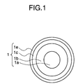
- Fig. 1 illustrates an example of the layer structure of the charging member according to the present invention.
- Fig. 2 illustrates another example of the layer structure of the charging member according to the present invention.
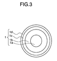
- Fig. 3 illustrates an example of the layer structure of a charging member before the remanufacturing process of the present invention is applied.
- Fig. 4 schematically illustrates an example of the construction of an abrasion means used in the present invention.
- Fig. 5 schematically illustrates an example of the construction of an electrophotographic apparatus having a process cartridge having the charging member of the present invention.
- the remanufacturing process of the present invention comprises the steps of carrying out mechanical abrasion to remove at least a surface layer provided on the charging member, and forming a layer on the surface laid bare by the abrasion.
- the charging member of the present invention has at least two layers on a conductive support and may have the shape of a roller, a blade or the like.
- the member in view of readiness for the mechanical abrasion, may preferably have the shape of a roller.
- Figs. 1 and 2 illustrate examples of the layer structure of the charging member having the shape of a roller according to the present invention.
- Fig. 3 illustrates an example of the layer structure of a charging member before the remanufacturing process of the present invention is applied.
- reference numeral 1 denotes a charging member; 1a, a conductive support; 1b, an elastic layer; 1c, a resistance control layer; and 1d and 1e, covering layers (or surface layers).
- the layer 1d (Fig. 3), which is a surface layer having caused difficulties or having deteriorated, standing before remanufacturing, is mechanically abraded to be removed in its entirety or in part, and thereafter a surface layer le is formed anew on the abraded surface to thereby make uniform the surface resistance of the charging roller and bring back the electrical properties and surface properties (lubricity and smoothness) required in charging members, to a satisfactory condition so that the charging roller can be reused (Fig. 1).
- the charging roller before reuse may be constituted of the elastic layer 1b and the surface layer 1d, having no resistance control layer 1c.
- the surface layer 1d may be removed by abrasion and the covering layer le may be formed on its periphery to provide the charging roller as shown in Fig. 2.
- the covering layers 1d (before remanufacture) and 1e (after remanufacture) may not necessarily be of the same type.
- the layer to be removed by abrasion may not necessarily be only the surface layer, and a layer or layers beneath the surface layer may be removed.
- the layer to be formed anew may also not necessarily be one layer, and a plurality of layers may be formed.
- the conductive support 1 used in the present invention may be made of metal such as iron, copper, stainless steel, aluminum or nickel, any of which may be used.
- the metal surface thereof may be further treated by plating for the purpose of rust-proofing or providing scratch resistance, but it is necessary not to damage the conductivity.
- the elastic layer 1b is endowed with an elasticity suitable for ensuring good and uniform close contact of the charging roller 1 with a photosensitive member 2 (Fig. 5).
- Conductivity of the elastic layer 1b is controlled by adding a conductive agent such as carbon black to an elastic material such as rubber. Its elasticity is controlled by adding a process oil, a plasticizer and so forth.
- the elastic material for the elastic layer 1b may specifically include, for example, natural rubber, synthetic rubbers such as ethylene propylene diene methylene rubber (EPDM), styrene-butadiene rubber (SBR), silicone rubber, urethane rubber, epichlorohydrin rubber, isoprene rubber (IR), butadiene rubber (BR), nitrile-butadiene rubber (NBR) and chloroprene rubber (CR), and also resins such as polyamide resin, polyurethane resin, silicone resin and fluorine resin.
- a foam of the above elastic material may also be used in the elastic layer 1b.
- the resistance control layer 1c is often provided in order to control the resistance of charging members.
- Materials for the resistance control layer 1c may specifically include resins such as polyamide resin, polyurethane resin, fluorine resin and silicone resin, and also epichlorohydrin rubber, urethane rubber, chloroprene rubber and acrylonitrile rubbers.
- a conductive material may be dispersed also in the resistance control layer 1c, which includes conductive particles such as carbon black and carbon graphite, conductive metal oxides such as conductive titanium oxide, conductive zinc oxide and conductive tin oxide, as well as conductive agents such as alkali metal salts and ammonium salts.
- the covering layers 1d and le are often provided in order to prevent a plasticizer or the like in the elastic layer 1b from bleeding out to the surface of the charging roller and to maintain the lubricity and smoothness of the charging roller surface.
- the covering layers 1d and 1e are each provided by coating or tubing.
- materials therefor may specifically include resins such as polyamide resin, polyurethane resin, acrylic resin, fluorine resin and silicone resin, and also epichlorohydrin rubber, urethane rubber, chloroprene rubber and acrylonitrile rubbers.
- the coating may be carried out by a process including dip coating, roll coating and spray coating.
- materials therefor may specifically include nylon 12, PFA (tetrafluoroethylene-perfluoroalkyl vinyl ether copolymer resin), PVDF (polyvinylidene fluoride), FEP (tetrafluoroethylene-hexafluoropropylene copolymer resin), and also thermoplastic elastomers of a polystyrene type, a polyolefin type, a polyvinyl chloride type, a polyurethane type, a polyester type or a polyamide type.
- the tubing may be either heat-shrinkable tubing or non-heat-shrinkable tubing.
- a conductive material which includes conductive particles such as carbon black and carbon graphite, conductive metal oxides such as conductive titanium oxide, conductive zinc oxide and conductive tin oxide, as well as conductive agents such as alkali metal salts and ammonium salts.
- the charging roller of the present invention When the charging roller of the present invention is used, its surface irregularities may cause delicate charge non-uniformity if the charging roller has a rough surface, without regard to whether the relation between the charging roller and the photosensitive member is of contact or non-contact, and consequently faulty images may occur.
- the charging roller may preferably have a smoother surface and should preferably have a 10-point average surface roughness Rz of 100 ⁇ m or less, and more preferably of 15 ⁇ m or less, according to JIS B0601 standard of surface roughness.
- the covering layers 1d and 1e should each preferably have a layer thickness of 5,000 ⁇ m or less, and more preferably within the range of from 1 to 500 ⁇ m. So long as the covering layer has a layer thickness within the range of from 1 to 500 ⁇ m, the function of a layer lying beneath the covering layer can be well brought out and hence it is not especially necessary to impart various functions to the covering layer. If the covering layer is formed in a layer thickness larger than 500 ⁇ m, it may become necessary to especially make adjustment again in order to control various functions of the covering layer. On the other hand, if in a layer thickness smaller than 1 ⁇ m, there is a possibility that the covering layer can not withstand its friction with the photosensitive member.
- the charging member may preferably have a volume resistivity within the range of from 104 to 1014 ⁇ cm. If it is less than 104 ⁇ cm, and when pinholes have occurred in the photosensitive member for some reason and the part where the pinholes are present comes to the charging zone at which the photosensitive member and the charging member form a nip, a leakage of currents may occur across the charging member and the pinholes of the photosensitive member to cause a great drop of voltage at the power supply.
- the charging becomes poor at the nip between the charging member and the photosensitive member in its entire longitudinal direction, so that in actual images an uneven image appears at every rotational period of the photosensitive member, which appears in black stripes in reverse development or in white stripes in regular development, resulting in a lowering of image quality. If on the other hand it exceeds 1014 ⁇ cm, the resistance of the charging member may be too high to charge the photosensitive member at the desired potential, resulting in poor charging. This problem can be settled by correspondingly increasing the voltage to be supplied, which, however, makes efficiency very poor and is not practical.
- a primer or the like may be applied between the resistance control layer 1c and the covering layer 1d or 1e or between the elastic layer 1b and the covering layer 1d or 1e in order to strengthen the adhesion between the resistance control layer 1c and the covering layer 1d or 1e or between the elastic layer 1b and the covering layer 1d or 1e.
- the covering layer may be either a single layer or a multiple layer formed of two or more layers.
- the volume resistivity is measured according to JIS K6911.
- the abrasion may usually be carried out under dry condition (dry abrasion), but may preferably be carried out under wet condition (wet abrasion) especially when the surface roughness must be made small.
- dry abrasion dry abrasion
- wet abrasion wet abrasion
- the charging roller 1 is rotated in the direction of an arrow R1, and the periphery 20a of a cylindrical grinding wheel 20 is brought into contact with the periphery of the roller under an appropriate pressure. While the grinding wheel 20 is rotated in the direction of an arrow R2, it is further moved in the direction of an arrow K1 to thereby abrade the charging roller 1 along its periphery.
- an organic solvent or an oil is used in order to keep the abrading surface of the charging roller in wet condition.
- the organic solvent or oil has a possibility of contaminating the photosensitive member, a member to be charged, and hence water may preferably be used.
- water may preferably be used.
- Fig. 5 schematically illustrates the construction of an electrophotographic apparatus having a process cartridge having the charging member of the present invention as a primary charging means.
- reference numeral 2 denotes an electrophotographic photosensitive member, which is rotated around an axis 3 in the direction of an arrow at a given peripheral speed.
- the photosensitive member 2 is uniformly charged on its periphery to a positive or negative, given potential through the charging member 1 of the present invention, serving as a primary charging means.
- the photosensitive member thus charged is then photoimagewise exposed to light 4 emitted from an imagewise exposure means (not shown) for slit exposure or laser beam scanning exposure.
- electrostatic latent images are successively formed on the periphery of the photosensitive member 2.
- the electrostatic latent images thus formed are subsequently developed by toner by the operation of a developing means 5.
- the resulting toner-developed images are then successively transferred by the operation of a transfer means 6, to the surface of a transfer medium 7 fed from a paper feed section (not shown) to the part between the photosensitive member 2 and the transfer means 6 in the manner synchronized with the rotation of the photosensitive member 2.
- the transfer medium 7 on which the images have been transferred is separated from the surface of the photosensitive member, is led through an image fixing means 8, where the images are fixed, and is then printed out of the apparatus as a copied material (copy).
- the surface of the photosensitive member 2 after the transfer of images is brought to removal of the toner remaining after the transfer, through a cleaning means 9.
- the photosensitive member is cleaned on its surface, further subjected to charge elimination by pre-exposure light 10 emitted from a pre-exposure means (not shown), and then repeatedly used for the formation of images.
- the charging member 1 is a contact charging member, the pre-exposure is not necessarily required.
- the apparatus may be constituted of a combination of plural components integrally joined as a process cartridge from among the constituents such as the above electrophotographic photosensitive member 2, charging member 1, developing means 5 and cleaning means 9 so that the process cartridge is detachable from the body of the electrophotographic apparatus such as a copying machine or a laser beam printer.
- the electrophotographic photosensitive member 2, the developing means 5 and the cleaning means 9 may be integrally supported together with the charging member 1 to form a process cartridge 11 that is detachable from the body of the apparatus through a guide means such as a rail 12 provided in the body of the apparatus.
- the light 4 of the imagewise exposure is light reflected from, or transmitted through, an original, or light irradiated by the scanning of a laser beam, the driving of an LED array or the driving of a liquid crystal shutter array according to signals obtained by reading an original and converting the information into signals.
- a charging roller as the charging member of the present invention was produced according to the following procedure.
- a process cartridge (model name: EP-E Toner Cartridge), used in a laser beam printer (trade name: LBP-8 Mark IV; manufactured by Canon Inc.), was detached after images were reproduced on 8,000 sheets. Its charging roller was taken out of the process cartridge, and was used as a base for the charging roller of the present invention. The surface layer of the charging roller thus taken out was removed by wet abrasion using water.
- the above materials were dispersed and dissolved in a methanol/toluene mixed solvent to prepare a covering layer coating composition.
- This coating composition was coated on the charging roller by dipping to form a covering layer of 20 ⁇ m thick.
- the charging roller of the present invention was obtained.
- the surface roughness (Rz) of the charging roller obtained was also measured by the method previously described. Results obtained are shown in Table 1.
- This charging roller was set in a virgin process cartridge (trade name: EP-E Toner Cartridge) and was used as a charging roller located at the primary charging assembly of the above laser beam printer to make a 6,000 sheet image reproduction running test. Images obtained at the initial stage and after the 6,000 sheet running were visually observed to evaluate image quality. Results obtained are shown in Table 2. In Table 2, “A” indicates that the images obtained are good; “B”, practically usable; and “C”, practically unusable.
- the above image reproduction running test was made in an environment of temperature 15°C and humidity 10% (environment 1) and in an environment of temperature 30°C and humidity 80% (environment 2).
- a charging roller as the charging member of the present invention was produced according to the following procedure. (by weight) SBR 100 parts Carbon black 30 parts Zinc oxide 5 parts Fatty acid 2 parts
- a vulcanizing agent 0.5 part by weight of sulfur and as vulcanizing accelerators 1 part by weight of a thiazole type vulcanizing accelerator and 1 part by weight of a thiurum type vulcanizing accelerator were added, all based on 100 parts by weight of the material rubber SBR, followed by kneading for 10 minutes by means of a twin-roll mill cooled to 20°C.
- the compound thus obtained was vulcanizing-molded around a stainless steel mandrel of 6 mm diameter by means of a press molding machine to form an elastic layer so as to have the shape of a roller of 12 mm in external diameter.
- the above materials were dispersed and dissolved in a methyl ethyl ketone (MEK) solvent to prepare a resistance control layer coating composition.
- MEK methyl ethyl ketone
- This coating composition was coated on the above elastic layer by dipping to form a resistance control layer in a layer thickness of 150 ⁇ m.
- the above materials were dispersed and dissolved in a methanol/toluene mixed solvent to prepare a surface layer coating composition.
- This coating composition was coated on the resistance control layer by dipping to form a surface layer in a layer thickness of 20 ⁇ m, followed by drying to produce a charging roller.
- a charging roller On the surface of the charging roller thus obtained, however, spitting having a diameter of about 1 mm was seen to have occurred.
- the surface layer having caused the spitting was removed by dry abrasion.
- a covering layer was formed again using the above surface layer coating composition. This time, no spitting occurred and the desired charging roller was obtained.
- a charging roller was produced in the same manner as in Example 1 except that a water-based polyurethane emulsion (solid matter: 10%) was used as a covering layer coating composition to form a covering layer in a layer thickness of 12 ⁇ m. Evaluation was made similarly. Results obtained are shown in Tables 1 and 2.
- a charging roller was produced in the same manner as in Example 1 except that the above materials were dispersed and dissolved in a methyl ethyl ketone (MEK) solvent to prepare a covering layer coating composition and a covering layer was formed in a layer thickness of 200 ⁇ m. Evaluation was made similarly. Results obtained are shown in Tables 1 and 2.
- MEK methyl ethyl ketone
- a charging roller was produced in the same manner as in Example 4 except that the carbon black used in the covering layer was replaced with 1 part by weight of lithium perchlorate and a covering layer was formed in a layer thickness of 20 ⁇ m. Evaluation was made similarly. Results obtained are shown in Tables 1 and 2.
- a charging roller was produced in the same manner as in Example 1 except that the above materials were dispersed and dissolved in a N-methylpyrrolidone (NMP) solvent to prepare a covering layer coating composition and a covering layer was formed in a layer thickness of 25 ⁇ m by spray coating. Evaluation was made similarly. Results obtained are shown in Tables 1 and 2.
- NMP N-methylpyrrolidone
- a charging roller was produced in the same manner as in Example 6 except that, before the coating of the covering layer coating composition, a silane coupling agent ⁇ -(2-aminoethyl)aminopropylmethyldimethoxysilane was coated as a primer on the surface (abraded surface) by dipping, followed by drying, and thereafer the covering layer was formed thereon. Evaluation was made similarly. Results obtained are shown in Tables 1 and 2.
- a charging roller as the charging member of the present invention was produced according to the following procedure.
- a process cartridge (model name: EP-E Toner Cartridge), used in a laser beam printer (trade name: LBP-8 Mark IV; manufactured by Canon Inc.), was detached after images were reproduced on 6,000 sheets. Its charging roller was taken out of the process cartridge, and was used as a base for the charging roller of the present invention. The surface layer of the charging roller thus taken out was removed by abrasion.
- the above materials were melt-kneaded and extruded into a tube, followed by stretching to obtain a tubing having an inner diameter of 14 mm and a wall thickness of 40 ⁇ m before heat shrinking.
- the charging roller previously obtained was inserted, followed by heating at 100°C for 2 minutes to cause the tubing to heat-shrink on the charging roller to form a covering layer thereon.
- the charging roller of the present invention was obtained.
- a process cartridge (model name: EP-E Toner Cartridge), used in a laser beam printer (trade name: LBP-8 Mark IV; manufactured by Canon Inc.), was detached after images were reproduced on 6,000 sheets. Its charging roller was taken out of the process cartridge, and was used as a base for the charging roller of the present invention. The surface layer of the charging roller thus taken out was removed by abrasion, and a covering layer was formed using a tubing as shown below. (by weight) Silicone resin 100 parts Carbon black 25 parts
- the above materials were melt-kneaded, and a tubing having an inner diameter of 10.5 mm and a wall thickness of 150 ⁇ m was obtained by extrusion.
- a tubing having an inner diameter of 10.5 mm and a wall thickness of 150 ⁇ m was obtained by extrusion.
- compressed air was blown and, while expanding the inner diameter of the tubing, the above charging roller having been abraded was inserted to the tubing. Thereafter, the compressed air was stopped blowing and the tubing was caused to shrink to form a covering layer.
- the charging roller of the present invention was obtained.
- a charging roller was produced in the same manner as in Example 9 except that the above materials were used to form a covering layer. Evaluation was made similarly. Results obtained are shown in Tables 1 and 2.
- a charging roller was produced in the same manner as in Example 8 except that the nylon 12 used in the tubing was replaced with 100 parts by weight of polyurethane resin. Evaluation was made similarly. Results obtained are shown in Tables 1 and 2.
- Example 4 The charging roller remanufactured in Example 4 and on which each evaluation and image reproduction running test were made was secondly remanufactured in the following way.
- the charging roller was abraded in the depth direction by 100 ⁇ m as an abrasion depth. Since immediately after the first remanufacturing the surface layer was in a layer thickness of 200 ⁇ m, it follows that, in the abrasion depth of 100 ⁇ m, the layer was removed by about a half.
- the above materials were melt-kneaded, and a tubing having an inner diameter of 10.5 mm and a wall thickness of 80 ⁇ m was obtained by extrusion.
- a tubing having an inner diameter of 10.5 mm and a wall thickness of 80 ⁇ m was obtained by extrusion.
- compressed air was blown and, while expanding the inner diameter of the tubing, the above charging roller having been abraded was inserted to the tubing. Thereafter, the compressed air was stopped blowing and the tubing was caused to shrink to form a covering layer.
- the charging roller of the present invention was obtained.
- a process cartridge (model name: EP-E Toner Cartridge), used in a laser beam printer (trade name: LBP-8 Mark IV; manufactured by Canon Inc.), was detached after images were reproduced on 6,000 sheets. Its charging roller was taken out of the process cartridge. To the surface of the charging roller taken out, powdery developer (toner) had adhered.
- This charging roller was set in a virgin process cartridge (trade name: EP-E Toner Cartridge) as it was, without means such as cleaning, and was used as a charging roller located at the primary charging assembly of the above laser beam printer. Evaluation was made in the same manner as in Example 1. Here, with regard to resistance, that of the charging roller before the running test, on which the toner had adhered to its surface, was measured. Results obtained are shown in Tables 1 and 2.
- a process cartridge (model name: EP-E Toner Cartridge), used in a laser beam printer (trade name: LBP-8 Mark IV; manufactured by Canon Inc.), was detached after images were reproduced on 6,000 sheets. Its charging roller was taken out of the process cartridge. To the surface of the charging roller taken out, powdery developer (toner) had adhered.
- the charging roller was immersed in MEK and cleaned with a brush.
- the charging roller having been thus cleaned was seen to have minute pinholes on its surface layer and its underlying resistance control layer was seen. Since this could not be put in practical use, neither measurement of surface roughness nor evaluation of images were made.
- a charging roller was produced in the same manner as in Example 1 except that no covering layer was formed after the abrasion. Evaluation was made similarly. Results obtained are shown in Tables 1 and 2.
- Table 1 Results of Measurement of Roller Resistance and Surface Roughness Resistance (M ⁇ ) Surface roughess Edge Middle Edge Rz ( ⁇ m) Example: 1 0.85 0.89 0.95 3.688 2 0.96 1.08 1.02 5.023 3 2.00 1.91 1.85 3.221 4 1.06 0.91 1.23 3.048 5 1.11 0.97 1.20 2.366 6 1.22 1.05 1.18 4.293 7 0.95 1.08 1.27 4.510 8 1.23 1.15 1.08 4.025 9 1.59 1.90 1.82 4.683 10 2.34 2.56 2.52 4.443 11 1.03 1.23 1.25 4.203 12 1.31 1.00 0.94 3.914 Comparative Example: 1 2.63 3.69 3.30 3.721 2 1.24 1.06 1.11 - 3 0.76 0.81 0.80 9.533 Table 2 Results of Image Reproduction Running Test Environment 1 Environment 2 Initial 6,000sh.
Landscapes
- Physics & Mathematics (AREA)
- Engineering & Computer Science (AREA)
- Plasma & Fusion (AREA)
- General Physics & Mathematics (AREA)
- Electrostatic Charge, Transfer And Separation In Electrography (AREA)
Applications Claiming Priority (3)
| Application Number | Priority Date | Filing Date | Title |
|---|---|---|---|
| JP25203694 | 1994-10-18 | ||
| JP25203694 | 1994-10-18 | ||
| JP252036/94 | 1994-10-18 |
Publications (3)
| Publication Number | Publication Date |
|---|---|
| EP0708382A2 true EP0708382A2 (de) | 1996-04-24 |
| EP0708382A3 EP0708382A3 (de) | 1996-12-27 |
| EP0708382B1 EP0708382B1 (de) | 2002-01-30 |
Family
ID=17231690
Family Applications (1)
| Application Number | Title | Priority Date | Filing Date |
|---|---|---|---|
| EP95307155A Expired - Lifetime EP0708382B1 (de) | 1994-10-18 | 1995-10-10 | Verfahren zur Wiederherstellung eines Aufladungselements |
Country Status (6)
| Country | Link |
|---|---|
| US (1) | US6337103B1 (de) |
| EP (1) | EP0708382B1 (de) |
| KR (1) | KR100222216B1 (de) |
| CN (1) | CN1140004C (de) |
| DE (1) | DE69525214T2 (de) |
| SG (1) | SG46147A1 (de) |
Cited By (1)
| Publication number | Priority date | Publication date | Assignee | Title |
|---|---|---|---|---|
| US5823929A (en) * | 1996-12-20 | 1998-10-20 | Genicom Corporation | Reconditioning primary charge rollers for electrostatographic imaging machines |
Families Citing this family (5)
| Publication number | Priority date | Publication date | Assignee | Title |
|---|---|---|---|---|
| US8448336B2 (en) * | 2008-07-03 | 2013-05-28 | Lexmark International, Inc. | Electrophotographic roller with resistance to nip banding |
| CN101968615A (zh) * | 2010-09-28 | 2011-02-09 | 珠海天威飞马打印耗材有限公司 | 充电辊再生方法 |
| WO2012067695A1 (en) | 2010-11-15 | 2012-05-24 | Masco Bath Corporation | Method for bathing vessel having wood-containing base board |
| CN105629694A (zh) * | 2015-12-29 | 2016-06-01 | 徐文欢 | 一种显影辊和感光鼓的隔离装置 |
| KR101843387B1 (ko) | 2016-10-13 | 2018-05-14 | 재생환경협동조합 | 차지롤러의 재제조방법 및 이에 의하여 재제조된 차지롤러 |
Family Cites Families (15)
| Publication number | Priority date | Publication date | Assignee | Title |
|---|---|---|---|---|
| DE3882462T2 (de) * | 1987-03-18 | 1994-02-24 | A V Syntec Pty Ltd | Oberflächen zum ausüben von sport. |
| JPH0664393B2 (ja) | 1988-02-11 | 1994-08-22 | キヤノン株式会社 | 帯電用部材、それを有する接触帯電装置、それを用いた接触帯電方法およびそれを有する電子写真装置 |
| US5035089A (en) * | 1990-01-29 | 1991-07-30 | Pauli & Griffin | Blast media recovery and cleaning system |
| JPH06266206A (ja) * | 1993-01-13 | 1994-09-22 | Ricoh Co Ltd | 帯電ローラ |
| JPH05224506A (ja) * | 1992-02-13 | 1993-09-03 | Canon Inc | 帯電装置 |
| JP2784976B2 (ja) * | 1992-06-24 | 1998-08-13 | キヤノン株式会社 | 再生シリンダを用いた再生電子写真感光ドラムユニット |
| US5320879A (en) * | 1992-07-20 | 1994-06-14 | Hughes Missile Systems Co. | Method of forming coatings by plasma spraying magnetic-cerment dielectric composite particles |
| US5309200A (en) * | 1992-09-11 | 1994-05-03 | Michlin Steven B | Photoreceptor drum, charge roller and developer brush spinner device |
| US6096395A (en) | 1992-12-16 | 2000-08-01 | Tokai Rubber Industries, Ltd. | Roll including foam body and method of producing the roll |
| JPH06202533A (ja) * | 1992-12-28 | 1994-07-22 | Canon Inc | 感光ドラム及び現像スリーブのリサイクル方法 |
| JPH0792887A (ja) * | 1993-07-20 | 1995-04-07 | Canon Inc | シール部材、プロセスカートリッジ、画像形成装置及びプロセスカートリッジの組立方法 |
| JPH07128958A (ja) * | 1993-09-10 | 1995-05-19 | Ricoh Co Ltd | 帯電ローラおよびそれを用いた画像形成装置 |
| US5565968A (en) * | 1994-09-02 | 1996-10-15 | Bridgestone Corporation | Developing roller, and method and apparatus for developing latent images using the roller |
| US5569543A (en) * | 1994-10-31 | 1996-10-29 | Inorganic Coatings, Inc. | Method for coating a brake rotor and brake rotor |
| JP3225491B2 (ja) * | 1994-12-07 | 2001-11-05 | キヤノン株式会社 | 帯電ローラの再生方法 |
-
1995
- 1995-10-10 DE DE69525214T patent/DE69525214T2/de not_active Expired - Lifetime
- 1995-10-10 EP EP95307155A patent/EP0708382B1/de not_active Expired - Lifetime
- 1995-10-12 US US08/542,339 patent/US6337103B1/en not_active Expired - Lifetime
- 1995-10-13 SG SG1995001552A patent/SG46147A1/en unknown
- 1995-10-17 KR KR1019950035759A patent/KR100222216B1/ko not_active Expired - Lifetime
- 1995-10-18 CN CNB951187082A patent/CN1140004C/zh not_active Expired - Fee Related
Non-Patent Citations (1)
| Title |
|---|
| None |
Cited By (1)
| Publication number | Priority date | Publication date | Assignee | Title |
|---|---|---|---|---|
| US5823929A (en) * | 1996-12-20 | 1998-10-20 | Genicom Corporation | Reconditioning primary charge rollers for electrostatographic imaging machines |
Also Published As
| Publication number | Publication date |
|---|---|
| KR100222216B1 (ko) | 1999-10-01 |
| KR960015112A (ko) | 1996-05-22 |
| US6337103B1 (en) | 2002-01-08 |
| CN1140004C (zh) | 2004-02-25 |
| EP0708382A3 (de) | 1996-12-27 |
| DE69525214T2 (de) | 2002-07-11 |
| EP0708382B1 (de) | 2002-01-30 |
| DE69525214D1 (de) | 2002-03-14 |
| CN1132950A (zh) | 1996-10-09 |
| SG46147A1 (en) | 1998-02-20 |
Similar Documents
| Publication | Publication Date | Title |
|---|---|---|
| US7151904B2 (en) | Conductive member and process cartridge and image forming apparatus using the same | |
| EP0708381B1 (de) | Aufladungselement, Verfahren zur Herstellung eines Aufladungselements, und Arbeitseinheit mit diesem Aufladungselement | |
| EP0708382B1 (de) | Verfahren zur Wiederherstellung eines Aufladungselements | |
| JP3729123B2 (ja) | 帯電装置及びこれを用いた画像形成装置 | |
| JP3225491B2 (ja) | 帯電ローラの再生方法 | |
| JPH11237783A (ja) | 画像形成装置および帯電ローラ | |
| EP1288741B1 (de) | Arbeitseinheit, elektrophotographisches Gerät und Bilderzeugungsverfahren | |
| JPH1039647A (ja) | 画像形成装置 | |
| JP3278331B2 (ja) | 帯電部材、該帯電部材の製造方法及び該帯電部材を有するプロセスカートリッジ | |
| JPH08171264A (ja) | 帯電部材の再生方法、該再生方法により再生された帯電部材及び該帯電部材を有するプロセスカートリッジ | |
| JP2002132014A (ja) | 帯電部材及び該帯電部材を有する画像形成装置 | |
| JP3115198B2 (ja) | 帯電部材 | |
| JP2000206779A (ja) | トナ―担持体及び画像形成装置 | |
| US12436483B2 (en) | Endless belt, belt unit, and image forming apparatus | |
| US12105435B2 (en) | Conductive roller | |
| JPH11160959A (ja) | 帯電部材、プロセスカートリッジ及び画像形成装置 | |
| JP3472053B2 (ja) | 帯電部材、プロセスカートリッジ及び画像形成装置 | |
| JP3478718B2 (ja) | 帯電部材、プロセスカートリッジ及び画像形成装置 | |
| JPH07219307A (ja) | 接触帯電装置及びその帯電部材の抵抗層形成方法 | |
| JPH08202116A (ja) | 帯電ローラ部材 | |
| JP3478718B6 (ja) | 帯電部材、プロセスカートリッジ及び画像形成装置 | |
| JPH11160960A (ja) | 帯電部材及び電子写真装置 | |
| JPH10123896A (ja) | 画像形成方法及び画像形成装置 | |
| JPH11212331A (ja) | 帯電部材およびそれを用いた電子写真装置 | |
| JPH11119511A (ja) | 帯電部材の製造方法およびその方法により得られた帯電部材 |
Legal Events
| Date | Code | Title | Description |
|---|---|---|---|
| PUAI | Public reference made under article 153(3) epc to a published international application that has entered the european phase |
Free format text: ORIGINAL CODE: 0009012 |
|
| AK | Designated contracting states |
Kind code of ref document: A2 Designated state(s): DE FR GB IT |
|
| PUAL | Search report despatched |
Free format text: ORIGINAL CODE: 0009013 |
|
| AK | Designated contracting states |
Kind code of ref document: A3 Designated state(s): DE FR GB IT |
|
| 17P | Request for examination filed |
Effective date: 19970507 |
|
| 17Q | First examination report despatched |
Effective date: 19990426 |
|
| RTI1 | Title (correction) |
Free format text: PROCESS FOR REMANUFACTURING A CHARGING MEMBER |
|
| GRAG | Despatch of communication of intention to grant |
Free format text: ORIGINAL CODE: EPIDOS AGRA |
|
| GRAG | Despatch of communication of intention to grant |
Free format text: ORIGINAL CODE: EPIDOS AGRA |
|
| GRAH | Despatch of communication of intention to grant a patent |
Free format text: ORIGINAL CODE: EPIDOS IGRA |
|
| GRAH | Despatch of communication of intention to grant a patent |
Free format text: ORIGINAL CODE: EPIDOS IGRA |
|
| GRAA | (expected) grant |
Free format text: ORIGINAL CODE: 0009210 |
|
| REG | Reference to a national code |
Ref country code: GB Ref legal event code: IF02 |
|
| AK | Designated contracting states |
Kind code of ref document: B1 Designated state(s): DE FR GB IT |
|
| REF | Corresponds to: |
Ref document number: 69525214 Country of ref document: DE Date of ref document: 20020314 |
|
| ET | Fr: translation filed | ||
| PLBE | No opposition filed within time limit |
Free format text: ORIGINAL CODE: 0009261 |
|
| STAA | Information on the status of an ep patent application or granted ep patent |
Free format text: STATUS: NO OPPOSITION FILED WITHIN TIME LIMIT |
|
| 26N | No opposition filed | ||
| PGFP | Annual fee paid to national office [announced via postgrant information from national office to epo] |
Ref country code: IT Payment date: 20081020 Year of fee payment: 14 |
|
| PGFP | Annual fee paid to national office [announced via postgrant information from national office to epo] |
Ref country code: FR Payment date: 20081024 Year of fee payment: 14 |
|
| REG | Reference to a national code |
Ref country code: FR Ref legal event code: ST Effective date: 20100630 |
|
| PG25 | Lapsed in a contracting state [announced via postgrant information from national office to epo] |
Ref country code: FR Free format text: LAPSE BECAUSE OF NON-PAYMENT OF DUE FEES Effective date: 20091102 |
|
| PG25 | Lapsed in a contracting state [announced via postgrant information from national office to epo] |
Ref country code: IT Free format text: LAPSE BECAUSE OF NON-PAYMENT OF DUE FEES Effective date: 20091010 |
|
| PGFP | Annual fee paid to national office [announced via postgrant information from national office to epo] |
Ref country code: DE Payment date: 20131031 Year of fee payment: 19 Ref country code: GB Payment date: 20131018 Year of fee payment: 19 |
|
| REG | Reference to a national code |
Ref country code: DE Ref legal event code: R119 Ref document number: 69525214 Country of ref document: DE |
|
| GBPC | Gb: european patent ceased through non-payment of renewal fee |
Effective date: 20141010 |
|
| PG25 | Lapsed in a contracting state [announced via postgrant information from national office to epo] |
Ref country code: DE Free format text: LAPSE BECAUSE OF NON-PAYMENT OF DUE FEES Effective date: 20150501 Ref country code: GB Free format text: LAPSE BECAUSE OF NON-PAYMENT OF DUE FEES Effective date: 20141010 |