EP0715376A2 - Connecteur électrique - Google Patents
Connecteur électrique Download PDFInfo
- Publication number
- EP0715376A2 EP0715376A2 EP95107399A EP95107399A EP0715376A2 EP 0715376 A2 EP0715376 A2 EP 0715376A2 EP 95107399 A EP95107399 A EP 95107399A EP 95107399 A EP95107399 A EP 95107399A EP 0715376 A2 EP0715376 A2 EP 0715376A2
- Authority
- EP
- European Patent Office
- Prior art keywords
- annular
- cable
- guide body
- flat cable
- collar portion
- Prior art date
- Legal status (The legal status is an assumption and is not a legal conclusion. Google has not performed a legal analysis and makes no representation as to the accuracy of the status listed.)
- Granted
Links
- 230000008878 coupling Effects 0.000 claims abstract description 8
- 238000010168 coupling process Methods 0.000 claims abstract description 8
- 238000005859 coupling reaction Methods 0.000 claims abstract description 8
- 230000002093 peripheral effect Effects 0.000 claims description 13
- 238000003780 insertion Methods 0.000 claims description 2
- 230000037431 insertion Effects 0.000 claims description 2
- 210000002105 tongue Anatomy 0.000 description 4
- 230000001939 inductive effect Effects 0.000 description 3
- 230000004048 modification Effects 0.000 description 3
- 238000012986 modification Methods 0.000 description 3
- 230000004323 axial length Effects 0.000 description 2
- 238000010276 construction Methods 0.000 description 2
- 238000000034 method Methods 0.000 description 2
- 230000003014 reinforcing effect Effects 0.000 description 2
- 241000217377 Amblema plicata Species 0.000 description 1
- 229930182556 Polyacetal Natural products 0.000 description 1
- 230000000994 depressogenic effect Effects 0.000 description 1
- 238000006073 displacement reaction Methods 0.000 description 1
- 229920006351 engineering plastic Polymers 0.000 description 1
- 230000007246 mechanism Effects 0.000 description 1
- 238000000465 moulding Methods 0.000 description 1
- 230000007935 neutral effect Effects 0.000 description 1
- 229920003023 plastic Polymers 0.000 description 1
- 229920006324 polyoxymethylene Polymers 0.000 description 1
- 238000004804 winding Methods 0.000 description 1
Images


Classifications
-
- B—PERFORMING OPERATIONS; TRANSPORTING
- B60—VEHICLES IN GENERAL
- B60R—VEHICLES, VEHICLE FITTINGS, OR VEHICLE PARTS, NOT OTHERWISE PROVIDED FOR
- B60R16/00—Electric or fluid circuits specially adapted for vehicles and not otherwise provided for; Arrangement of elements of electric or fluid circuits specially adapted for vehicles and not otherwise provided for
- B60R16/02—Electric or fluid circuits specially adapted for vehicles and not otherwise provided for; Arrangement of elements of electric or fluid circuits specially adapted for vehicles and not otherwise provided for electric constitutive elements
- B60R16/023—Electric or fluid circuits specially adapted for vehicles and not otherwise provided for; Arrangement of elements of electric or fluid circuits specially adapted for vehicles and not otherwise provided for electric constitutive elements for transmission of signals between vehicle parts or subsystems
- B60R16/027—Electric or fluid circuits specially adapted for vehicles and not otherwise provided for; Arrangement of elements of electric or fluid circuits specially adapted for vehicles and not otherwise provided for electric constitutive elements for transmission of signals between vehicle parts or subsystems between relatively movable parts of the vehicle, e.g. between steering wheel and column
-
- H—ELECTRICITY
- H01—ELECTRIC ELEMENTS
- H01R—ELECTRICALLY-CONDUCTIVE CONNECTIONS; STRUCTURAL ASSOCIATIONS OF A PLURALITY OF MUTUALLY-INSULATED ELECTRICAL CONNECTING ELEMENTS; COUPLING DEVICES; CURRENT COLLECTORS
- H01R35/00—Flexible or turnable line connectors, i.e. the rotation angle being limited
- H01R35/02—Flexible line connectors without frictional contact members
- H01R35/025—Flexible line connectors without frictional contact members having a flexible conductor wound around a rotation axis
Definitions
- the present invention is concerned with the subject matters described in co-pending US Patent Applications Serial Nos. 08/361,043 (filed December 21, 1994) and 08/364,043 (filed December 27, 1994).
- the present invention relates in general to electric connectors, and more particularly to electric connectors of a type which connects two electric parts which are rotatable relative to each other. More specifically, the present invention is concerned with a cable type electric connector which generally comprises a first member connected to one fixed electrical part, and a second member connected to the other electrical part which rotates relative to the fixed electric part and a rolled resilient electric cable having both ends connected to the first and second members.
- a cable type electric connector which comprises an annular casing having a cylindrical wall; an annular rotor having a concentric collar portion, the collar portion being coaxially and rotatably received in the annular casing thereby to define therebetween a cable receiving annular space; an annular guide body concentrically and rotatably received in the cable receiving annular space, the annular guide body having a cable passing slot; a flat cable having an inner end connected to the collar portion and an outer end connected to the annular casing, the flat cable passing through the cable passing slot, so that when the collar portion and the annular casing make a relative rotation therebetween, the flat cable is forced to make a roll wound on the collar portion in one direction or a roll wound within the cylindrical wall of the annular casing in the other direction; and coupling means for coupling the annular guide body and said annular rotor in a manner to permit a relative rotation therebetween.
- a cable type electric connector which comprises an annular casing having a cylindrical wall; an annular rotor having a concentric collar portion, the collar portion being coaxially and rotatably received in the annular casing thereby to define therebetween a cable receiving annular space; an annular guide body concentrically and rotatably received in the cable receiving annular space, said annular guide body having a cable passing slot; a flat cable having an inner end connected to the collar portion and an outer end connected to the annular casing, said flat cable passing through the cable passing slot, so that when the collar portion and said annular casing make a relative rotation therebetween, the flat cable is forced to make a roll wound on the collar portion in one direction or a roll wound within the cylindrical wall of the annular casing in the other direction; a cable holder ring connected to a leading end of the collar portion, the cable holder ring having an annular groove into which one lateral edge of the flat cable is inserted; and a cable guide
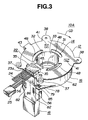
- a cable type electric connector 10A which is a first embodiment of the present invention.
- the connector 10A of this embodiment is arranged between an automotive steering wheel and a fixed portion of a vehicle body for connecting a first electric part mounted on the steering wheel and a second electric part mounted on the fixed portion.
- the first electric part is an air-bag device, a horn switch, an auto-speed control switch, an air conditioner control switch and/or an audio device control switch.
- the second electric part is a wire harness connector to which a battery, a vehicle collision sensor, a horn device, an auto-speed controller, an air conditioner and/or an audio device is connected through wires.
- the connector 10A takes a generally annular shape and generally comprises a rotor 12, an annular guide body 14, a cable holder ring 15, an annular casing 16, a retainer ring 17 and a cable holder 18.
- the rotor 12 is connected to the steering wheel and the annular casing 16 is connected to a fixed portion of the vehicle body, so that when the steering wheel is rotated, the rotor 12 is rotated relative to the fixed annular casing 16.
- the parts 12, 14, 15, 16, 17 and 18 are all constructed of an engineering plastic such as polyacetal or the like.
- the rotor 12 is connected to the steering wheel to rotate therewith.
- the annular guide body 14 is coaxially arranged below the rotor 12 in a manner to be rotatable relative thereto.
- the cable holder ring 15 is detachably connected to a center collar portion 33 of the rotor 12.
- the annular casing 16 is coaxially arranged below the rotor 12 in a manner to receive therein the annular guide body 14 and the cable holder ring 15 and arranged to be rotatable relative to the rotor 12.
- the retainer ring 17 is fixed to a leading end of the center collar portion 33 of the rotor 12 to rotatably retain the annular casing 16 to the center collar portion 33.
- the cable holder 18 is secured to an outer wall of the annular casing 16.
- the connector 10A has a cable receiving annular space 21 defined therein. More specifically, the annular space 21 is defined between the center collar portion 33 of the rotor 12 and a cylindrical wall 62 of the annular casing 16. Within the space 21, there is received a rolled flat cable 22 which is somewhat resilient.
- the rotor 12 upon assembly of the connector 10A, the rotor 12 is secured to a back side of the steering wheel having a steering shaft (not shown) passed through a center bore (no numeral) thereof.
- the steering shaft is operatively connected to a steering mechanism, so that, for steering the associated motor vehicle, the steering wheel can make about two or two and a half turns from its neutral position. That is, about four or five turns are available to the steering wheel between one locked terminal position and the other locked terminal position.
- the resilient flat cable 22 comprises a plurality of parallel wires embedded in an elongate flat insulating plastic cover.
- the flat cable 22 has inner and outer ends equipped with respective plugs 23a and 23b which are connected to the rotor 12 and the annular casing 16 in an after-mentioned manner.
- the rotor 12 comprises a generally circular upper wall 31 having a circular opening 32 at a center portion thereof.
- the center collar portion 33 extends downward from the peripheral portion of the circular opening 32.
- the circular upper wall 31 is formed at its upper surface with a pair of latching pawls 35 and 35 which face each other. These pawls 35 and 35 constitute an upper plug holder 36.
- the circular upper wall 31 is formed at its peripheral portion with four mounting lugs 37 and 38 which extend radially outwardly. These lugs 37 and 38 are to be secured to the back side of the steering wheel by means of bolts or the like.
- the circular upper wall 31 has further at the peripheral portion a stopper holding lug 43. At equally spaced portions of the circular upper wall 31, there are formed three tongues 41 each extending inwardly. The tongues 41 are resiliently flexible.
- each tongue 41 has at its leading end a small projection 42 which projects downward.
- the projections 42 function to guide the rotational movement of the annular guide body 14 relative to the rotor 12.
- Three arcuate slots 48 formed in the circular upper wall 31 are those which were produced when the molded rotor 12 was released from a molding die (not shown).
- the center collar portion 33 is formed with an axially extending slit 45 through which an inner end portion of the flat cable 22 passes.
- the slit 45 is concealed by an edge of a rectangular flat structure 44 which constitutes a part of the center collar portion 33.
- the slit 45 and the rectangular flat structure 44 thus constitute a so-called inside cable leading portion.
- the center collar portion 33 is formed on its upper part with three equally spaced ridges 46 each extending in a circumferential direction. As will become apparent as the description proceeds, these ridges 46 function to rotatably support the annular guide body 14.
- Each ridge 46 is formed with a sloped surface 47 at its lower side, as is seen from Fig. 1. The sloped surface 47 facilitates the insertion of the ridge 46 into an after-mentioned circular opening 101 of the annular guide body 14.
- the center collar portion 33 is formed around its lower part with an annular recess 49. As is seen from Fig. 4, the lower end of the center collar portion 33 is formed with four latching pawls 50 each extending downward. As will be described in detail hereinafter, these latching pawls 50 function to catch the retainer ring 17.
- the annular guide body 14 comprises a circular upper wall 102 having a circular opening 101 at a center portion thereof.
- the circular upper wall 102 is formed at its upper surface with an annular groove 118 which is concentric with the circular opening 101.
- inner and outer cylindrical walls 104 and 105 integrally connected to a lower surface of the circular upper wall 102 are inner and outer cylindrical walls 104 and 105 which are both coaxial with the circular opening 101. As shown, these two cylindrical walls 104 and 105 are connected at given portions to provide a smoothly curved slot 106 which extends radially to communicate the inside of the inner cylindrical wall 104 with the outside of the outer cylindrical wall 105.
- the curved slot 106 is defined between two mutually facing convex and concave walls 107 and 108, each extending between the inner and outer cylindrical walls 104 and 105.
- annular guide body 14 has the following unique structure.
- the lower surface of the circular upper wall 102 has, between the periphery of the center opening 101 and the inner cylindrical wall 104, an annular guide track 111 which is concentric with the center opening 101.
- the annular guide track 111 includes a sloped portion 114 which extends from the position of the curved slot 106 to an inflection portion 112 of about two third of the entire length of the annular guide track 111 and a flat portion (no numeral) which extends from the inflection portion 112 to the terminal position, that is, the position of the curved slot 106. That is, with increase of the circumferential distance from the curved slot 106 to the inflection portion 112, the height of the annular guide track 111 is gradually reduced, but from the inflexion portion 112 to the curved slot 106 through the remaining portion, the annular guide track 111 is in flash with the lower surface of the circular upper wall 102.
- the annular guide track 111 may be sloped throughout the entire length thereof. That is, in this case, with increase of the circumferential distance from the curved slot 106 to the same slot, the height of the annular guide track 111 is gradually reduced.
- the outer cylindrical wall 105 is formed at its outer cylindrical surface with a plurality of spaced ridges 116 each extending axially.
- About one third of the inner cylindrical wall 104 is formed at its inner cylindrical surface with a plurality of spaced ridges 116 each extending axially.
- the convex wall 107 is formed at its outer surface with several spaced ridges 116 each extending axially.
- the circular upper wall 102 has a peripheral edge portion 117 which is bent downward.
- the cable holder ring 15 comprises an annular base portion 53 which is mated with the annular recess 49 of the center collar portion 33 of the rotor 12, a cylindrical outer wall 54 which extends around the annular base portion 53 and an annular lower wall (no numeral) which extends between a lower end of the annular base portion 53 and that of the cylindrical outer wall 54.
- an annular groove 55 is defined by these three parts.
- the height of the annular base portion 53 is greater than that of cylindrical outer wall 54.
- the annular base portion 53 is formed with two slits 56 which are latchedly engaged with opposed ends of the afore-mentioned rectangular flat structure 44 of the center collar portion 33 of the rotor 12.
- the annular base portion 53 is reinforced by a plurality of reinforcing ribs each having a sloped top.
- the diameter of an imaginary circle which passes the tops of the ridges 116 of the inner cylindrical wall 104 of the annular guide body 14 is smaller than the diameter of the cylindrical outer wall 54 of the cable holder ring 15.
- the annular casing 16 comprises a circular lower wall 61 having a circular center opening 60 at a center portion thereof.
- a cylindrical wall 62 extends upward from the outer periphery of the circular lower wall 61.
- the circular lower wall 61 is formed around the center opening 60 with an annular recess 65 which is depressed downward from an upper major surface 64 of the circular lower wall 61.
- the annular recess 65 is concentric with the center opening 60. As will become apparent hereinafter, the annular recess 65 rotatably receives therein the cable holder ring 15.
- the upper major surface 64 of the circular lower wall 61 is formed with a convex annular portion 67 to which the lower edge of the flat cable 22 slidably contacts. That is, the middle part of the annular portion 67 is smoothly raised.
- An outer annular recess 66 is formed around the convex annular portion 67.
- the top of the convex annular portion 67 is higher than the top of the cylindrical outer wall 54 of the cable holder ring 15.
- the circular lower wall 61 of the annular casing 16 is formed on its lower surface with a plurality of reinforcing ribs 68 which extend radially outward. Furthermore, the circular lower wall 61 is formed at a lower side of the annular recess 65 with an annular groove 69 which is concentric with the center opening 60.
- the cylindrical wall 62 of the annular casing 16 is formed with an axially extending slit 77 through which an outer end portion of the flat cable 22 passes to the outside.
- the slit 77 is concealed by an edge of a rectangular flat structure 73 which constitutes a part of the cylindrical wall 62.
- the rectangular flat structure 73 has a downward extension 74 which is thicker than the flat structure 73.
- These flat structure 73 and the extension 74 thus constitute a so-called outside cable leading portion 72.
- Side walls 75 of this outside cable leading portion 72 are formed at lower portions thereof with respective latching pawls 76.
- each flat plate 78 is formed at a raised portion with a latching opening 79.
- the cylindrical wall 62 of the annular casing 16 is formed with an anchor stud 80.
- the retainer ring 17 comprises an annular base portion 91 which has a circular center opening 92.
- a small cylindrical wall 93 extends upward from the peripheral portion of the center opening 92.
- Four latching slots 95 are formed in the annular base portion 91, which are to be engaged with the above-mentioned latching pawls 50 of the rotor 12.
- a rectangular flat plate 96 extends upward from the annular base portion 91. When properly assembled, the flat plate 96 functions to cover an inner surface of the above-mentioned rectangular flat structure 44 of the center collar portion 33 of the rotor 12.
- the annular base portion 91 is formed with an annular recess 97 which faces the above-mentioned annular recess 65 of the annular casing 16.
- the annular recess 97 is formed with an annular bank 98 which is slidably engaged with the annular groove 69 of the annular casing 16.
- the cable holder 18 is formed with a cover portion 81.
- the cover portion 81 is formed with two rectangular openings 82 with which the above-mentioned latching pawls 76 of the annular casing 16 are engaged.
- the cover portion 81 is formed at its shoulder portion with two flat lugs 84.
- the lugs 84 are formed with latching pawls 85 which are engaged with the above-mentioned latching openings 79 of the annular casing 16.
- a rectangular plate 86 extends upward from the cover portion 81.
- the annular guide body 14 is coupled with the center collar portion 33 of the rotor 12 in such a manner that the peripheral edge of the circular opening 101 of the annular guide body 14 is slidably put on the three spaced ridges 46 of the collar portion 33. With this, the annular guide body 14 is rotatably held by the rotor 12. Under this condition, the small projections 42 of the tongues 41 of the rotor 12 are resiliently pressed against and slidably engaged with the annular groove 118 of the annular guide body 14 to assure smoothed rotation of the annular guide body 14 relative to the rotor 12.
- the plug 23a of the flat cable 22 is put between the latching pawls 35 and 35 of the rotor 12 to be fixed to the rotor 12.
- the flat cable 22 extending from the plug 23a is flexed downward along the rectangular flat structure 44 of the center collar portion 33, and then bent at generally right angles and led to the outside of the center collar portion 33 through the slit 45.
- the flat cable 22 is passed through the curved slot 106 of the annular guide body 14 permitting the leading end portion thereof to extend radially outward from the curved slot 106.
- the cable holder ring 15 is mated with the annular recess 49 of the center collar portion 33 of the rotor 12 in such a manner that the two slits 56 of the cable holder ring 15 are respectively engaged with opposed ends of the rectangular flat structure 44 of the center collar portion 33.
- the rotor 12 and the cable holder ring 15 are connected to constitute an annular integral unit to which the annular guide body 14 is rotatable.
- the exposed end portion of the flat cable 22 is then bent at generally right angles.
- the other plug 23a connected to the exposed leading end of the flat cable 22 is put between the latching pawls 76 of the annular casing 16 to be fixed to the annular casing 16.
- the annular casing 16 is coupled with the rotor 12 while receiving the annular guide body 14.
- the retainer ring 17 is put in the annular groove 69 (see Fig. 1) of the circular lower wall 61 of the annular casing 16 and then the retainer ring 17 is slightly turned to a certain position wherein the four latching slots 95 thereof respectively face the four latching pawls 50 of the center collar portion 33 of the rotor 12.
- the retainer ring 17 is pushed against the latching pawls 50 to establish latching engagement between the latching slots 95 and the latching pawls 50 and thus between the retainer ring 17 and the rotor 12.
- the cable holder 18 is attached to the outside cable leading portion 72 of the annular casing 16 in the afore-mentioned manner.
- the connector 10A is assembled. Under this assembled condition, the annular casing 16 is rotatably sandwiched, at the peripheral portion of the circular opening 60 thereof, between the lower annular surface of the cable holder ring 15 and the upper annular surface of the retainer ring 17 which are both fixed to the center collar portion 33 of the rotor 12.
- the flat cable 22 is received in the cable receiving annular space 21 which is defined between the center collar portion 33 of the rotor 12 and the cylindrical wall 62 of the annular casing 16.
- the flat cable 22 in the space 21 has an inner flat cable part wound around the center collar portion 33, an outer flat cable part rolled within the cylindrical wall 62 and an intermediate flat cable part passing through the curved slot 106 of the annular guide body 14.
- the inner and outer flat cable parts are rolled in opposite directions. That is, when the connector 10A is viewed from the top, the inner flat cable part is wound in a counterclockwise direction, while the outer flat cable part is rolled in a clockwise direction.
- the axial lengths of the inner and outer cylindrical walls 104 and 105 are about a half of the axial length of the cable receiving annular space 21. Thus, lower ends of these two walls 104 and 105 are prevented from abutting against the upper major surface 64 of the annular casing 16.
- a stopper 119 is employed which latches the anchor stud 80 of the annular casing 16 with the stopper holding lug 43 of the rotor 12. With the stopper 119, relative rotation between the rotor 12 and the annular casing 16 is suppressed.
- the rotor 12 when mounted on a vehicle, the rotor 12 is secured to the steering wheel and the annular casing 16 is connected to a fixed portion of the vehicle body.
- annular space defined between the center collar portion 33 of the rotor 12 and the inner cylindrical wall 104 of the annular guide body 14 will be called as “inner annular space”, and the other annular space defined between the outer cylindrical wall 105 of the annular guide body 14 and the cylindrical wall 62 of the annular casing 16 will be called as “outer annular space”.
- inner annular space the annular space defined between the center collar portion 33 of the rotor 12 and the inner cylindrical wall 104 of the annular guide body 14
- outer annular space defined between the outer cylindrical wall 105 of the annular guide body 14 and the cylindrical wall 62 of the annular casing 16 will be called as “outer annular space”.
- the flat cable 22 is permitted to move upward and then the flat cable 22 is raised upward by the convex upper major surface 64 of the annular casing 16, so that the flat cable 22 can easily ride over the cylindrical outer wall 54 of the cable holder ring 15.
- the flat cable 22 is drawn out through the curved slot 106 to the outer annular space while making a generally U-shaped turn back portion at the curved slot 106.
- the flat cable 22 thus drawn to the outer annular space is pressed against the cylindrical wall 62 of the annular casing 16 while making a larger roll thereof. Because the annular guide body 14 is rotatably held by the rotor 12, the counterclockwise rotation of the rotor 12 induces a slower rotation of the annular guide body 14 in the same direction.
- the flat cable 22 is drawn into the inner annular space through the curved slot 106 and wound around the center collar portion 33 of the rotor 12. That is, the flat cable 22 passes through the curved slot 106, rides over the cylindrical outer wall 54 of the cable holder ring 15 and comes into the inner annular space. During this, the flat cable 22 is pressed down by the sloped portion 114 of the annular guide track 111 and thus led into the annular groove 55 of the cable holder ring 15. Furthermore, during the rotation of the rotor 12, the flat cable 22 keeps pushing the convex wall 107 of the curved slot 106 inducing a slower rotation of the annular guide body 14 in the same direction.
- the upper major surface 64 of the annular casing 16 is formed with the convex annular portion 67 to which the lower edge of the U-shaped turn back portion of the flat cable 22 contacts. Accordingly, the flat cable 22 releasing from the annular groove 55 of the cable holder ring 15 is prevented from contacting the upper edge of the cylindrical outer wall 54 of the cable holder ring 15. This means that the smoothed movement of the flat cable 22 in the cable receiving annular space 21 is much promoted.
- the radius "L1" of the cylindrical outer wall 54 of the cable holder ring 15 is smaller than the radius "L2" of the inner cylindrical wall 104 of the annular guide body 14.
- the disengagement of the flat cable 22 from the annular groove 55 of the cable holder ring 15 can be made much smoother. That is, during the disengagement, the flat cable 22 is smoothly guided by the sloped portion 114.
- annular guide body 14 is rotatably supported by the rotor 14, it is possible to provide a certain space between the lower edges of the inner and outer cylindrical walls 104 and 105 of the annular guide body 14 and the upper major surface 64 of the circular lower wall 61 of the annular casing 16. This induces a smoothed rotation of the annular guide body 14 relative to the rotor 12.
- the upper major surface 64 of the annular casing 16 is formed with two annular ridges 122 and 122 to which the lower edge of the flat cable 22 slidably contacts. If desired, only one annular ridge or more than two annular ridges may be used.
- the ridges 116 formed on the inner and outer cylindrical walls 104 and 105 of the annular guide body 14 may be each shaped to extend around the cylindrical surface or diagonally on the cylindrical surface.
- Each ridge 116 may have a spherical or a tapered top.
- the concave wall 108 of the curved slot 106 may have ridges like the ridges 116, and the ridges 116 may be formed on the entire of the cylindrical surface of the inner cylindrical wall 104.
- center collar portion 33 of the rotor 12 and the cable holder ring 15 may be molded into a united structure.
- a cable type electric connector 10B which is a second embodiment of the present invention.
- means corresponding to the above-mentioned annular groove 55 and means corresponding to the above-mentioned annular guide track 111 are formed also around the outer cylindrical wall 105 of the annular guide body 14.
- the connector 10B generally comprises a flat cable 22, a cylindrical rotor 131, an annular casing 132 and an annular guide body 133.
- the cylindrical rotor 131 comprises a collar portion 135.
- the collar portion 135 has therearound an annular grooved portion 136 integrally connected thereto.
- the annular casing 132 is formed at its upper peripheral portion with a plurality of engaging pawls 138 by which a peripheral portion of an annular upper wall 137 of the annular guide body 133 is slidably supported. Between the annular casing 132 and the annular guide body 133, there is rotatably received the cylindrical rotor 131.
- the annular guide body 133 has inner and outer cylindrical walls 141 and 142 which extend downward from the annular upper wall 137. Although not shown in the drawing, a curved slot 143 corresponding to the curved slot 106 of the above-mentioned first embodiment 10A is provided, which extends between the inner and outer cylindrical walls 141 and 142.
- An inner annular space 144 is defined between the collar portion 135 of the rotor 131 and the inner cylindrical wall 141 of the annular guide body 133, and an outer annular space 145 is defined between the outer cylindrical wall 142 of the annular guide body 133 and the outer cylindrical wall 151 of the annular casing 132.
- the inner and outer annular spaces 144 and 145 have at their upper portions annular guide tracks 146 and 147 each being defined by the annular guide body 133. These tracks 146 and 147 are sloped in substantially the same manner as the above-mentioned annular guide track 111 of the first embodiment 10A.
- the outer annular space 145 has at its lower portion an annular groove 152 defined by the annular casing 132.
- the annular groove 152 extends around the inner surface of the outer cylindrical wall 151.
- the outer flat cable part (viz., a part of the flat cable 22 which is received in the outer annular space 145) is enforcedly put in the annular groove 152 and vertically positioned by the annular guide track 147.
- a cable type electric connector 10C which is a third embodiment of the present invention.
- Fig. 11 shows a steering wheel 2 to which the connector 10C is mounted.
- the steering wheel 2 has a center boss portion 3 whose lower side is covered by a lower cover 5.
- the lower cover 5 is formed with a circular recess 6 into which the connector 10C is neatly received.
- Denoted by numerals 4 and 4 are bolts by which the connector 10C is secured to the boss portion 3 of the steering wheel 2.
- the connector 10C of the third embodiment generally comprises a rotor 1012, an annular guide body 1014, an annular casing 1016 and a retainer ring 1017.
- the assembled connector 10C has a cable receiving annular space 1018 defined therein. Within the annular space 1018, there are operatively received a rolled flat cable 22 and a major portion of the annular guide body 1014.
- the rotor 1012 is connected to the steering wheel 2 and the annular casing 1016 is connected to a fixed portion of the vehicle body.
- the rotor 1012 comprises a collar portion 1051 and three arm portions 1052, 1053 and 1053 each extending radially outward from the upper end of the collar portion 1051.
- the largest arm portion 1052 has at its base part a recess 1055 through which an inner end portion of the flat cable 22 is inserted into the interior of the collar portion 1051.
- the arm portion 1052 is formed at its upper surface with a pair of latching pawls 1057 and 1057 which face each other. These latching pawls detachably hold a plug 23a which is fixed to an inner end of the flat cable 22.
- the latching pawls 1057 and 1057 thus constitute an upper plug holder 1056.
- the arm portion 1052 is further formed with two mounting lugs 1058 and 1058. These lugs are to be secured to the lower cover 5 of the steering wheel 2 through the bolts 4.
- the other arm portions 1053 and 1053 are formed at their leading ends with bolt openings 1059 and 1059 through which the bolts 4 pass for connecting the arm portions 1053 to the lower cover 5 of the steering wheel 2.
- the arm portions 1052, 1053 and 1053 are respectively formed with tongue-shaped projections 1061 which resiliently abut against an upper part of the annular guide body 1014 in an after-mentioned manner.
- the collar portion 1051 is formed on its upper part with three equally spaced ridges 1063 each extending in a circumferential direction. These ridges 1063 function to rotatably support the annular guide body 1014, as will become apparent hereinafter.
- the collar portion 1051 is formed at its lower end with four latching pawls 1064 which hold the retainer ring 1017 in an after-mentioned manner.
- the annular guide body 1014 comprises a circular upper wall 1073 and concentric inner and outer cylindrical walls 1071 and 1072 each projecting downward from the circular upper wall 1073.
- the inner cylindrical wall 1071 is formed at its inner surface with a plurality of circumferentially extending arcuate ridges 1075
- the outer cylindrical wall 1072 is formed at its outer surface with a plurality of circumferentially arcuate ridges 1076.
- Each ridge 1075 or 1076 may have a rectangular cross section or a spherical cross section.
- the inner and outer cylindrical walls 1071 and 1072 are connected at given portions to form a smoothly curved slot 1077 which extends radially to communicate the inside of the inner cylindrical wall 1071 and the outside of the outer cylindrical wall 1072.
- the curved slot 1077 is defined between two mutually facing convex and concave walls 1078a and 1078b, each extending between the inner and outer cylindrical walls 1071 and 1072.
- the circular upper wall 1073 has an outer diameter which is larger than that of the outer cylindrical wall 1072, and an inner diameter which is smaller than that of the inner cylindrical wall 1071.
- Denoted by numerals 1079 are arcuate slots which were formed in the annular guide body 1014 when associated molds were released from the product.
- the annular casing 1016 comprises a circular lower wall 1031 having a circular center opening 1032 at a center portion thereof.
- a cylindrical wall 1033 extends upward from the outer periphery of the circular lower wall 1031.
- the upper surface of the circular lower wall 1031 is flat, and, as is understood from Fig. 9, the lower surface of the wall 1031 is formed near the center opening 1032 thereof with an annular ridge 1035 by which an annular recess (no numeral) is defined around the center opening 1032.
- the cylindrical wall 1033 of the annular casing 1016 is formed with an axially extending slit 1037 through which an outer end portion of the flat cable 22 passes to the outside.
- the slit 1037 is concealed by a rectangular flat structure 1039.
- the slit 1037 and the rectangular flat structure 1039 constitute a so-called outside cable leading portion 1036.
- the flat structure 1039 has at a downward extension thereof a pair of latching pawls 1038 and 1038 which face each other.
- the latching pawls detachably hold a plug 23b which is fixed to an outer end of the flat cable 22.
- the cylindrical wall 62 is formed at its upper edge with an outwardly projected flange 1041.
- the retainer ring 1017 comprises an annular flange 1045 which is formed on the periphery thereof, an annular raised step 1043 which is concentric with the center opening thereof and a shorter cylindrical wall 1044 which extends upward from the peripheral portion of the center opening.
- Four latching slots 1046 are formed in the retainer ring 1017 at equally spaced intervals, which are to be engaged with the above-mentioned latching pawls 1064 of the rotor 1012.
- Fig. 9 shows the assembled condition of the connector 10C.
- the various parts of the connector 10C have the following positional relationship.
- the annular guide body 1014 is rotatably disposed about the collar portion 1051 of the rotor 1012 having the peripheral edge of the center opening thereof slidably engaged with the three ridges 1063 of the rotor 1012.
- the tongue-shaped projections 1061 of the rotor 12 resiliently abut against the circular upper wall 1073 of the annular guide body 1014. With this, relative play between the rotor 1012 and the annular guide body 1014 is suppressed.
- the two coupled parts 1012 and 1014 are put in the annular casing 1016 having the four latching pawls 1064 of the collar portion 1051 projected outward from the center opening 1032 of the annular casing 1016.
- the latching pawls 1064 are engaged with the latching slots 1046 of the retainer ring 1017 which is mated with the center opening 1032 of the annular casing 1016 from the back side.
- the annular guide body 1014 and the annular casing 1016 are rotatably disposed between the rotor 1012 and the retainer ring 1017.
- the outer peripheral portion of the circular upper wall 1073 of the annular guide body 1014 slidably puts on the outward flange 1041 of the annular casing 1016.
- the cable receiving annular space 1017 is divided into two major spaces which are an inner annular space defined between the collar portion 1051 of the rotor 1012 and the inner cylindrical wall 1071 of the annular guide body 1014 and an outer annular space defined between the outer cylindrical wall 1072 of the annular guide body 1014 and the cylindrical wall 1033 of the annular casing 1016. These two annular spaces are connected through the curved slot 1077 of the annular guide body 1014.
- the flat cable 22 upon assembly of the connector 10C, has an inner part thereof received in the inner annular space, an outer part thereof received in the outer annular space and a middle part passed through the curved slot 1077 of the annular guide body 1014. More specifically, like in the case of the above-mentioned first embodiment 10A, the inner part of the flat cable 22 is wound on the collar portion 1051 of the rotor 1012 in one direction and the outer part of the flat cable 22 is rolled in the other direction. That is, when the connector 10C of Fig. 9 is viewed from the top, the inner flat cable part is rolled in a counterclockwise direction and the outer flat cable part is rolled in a clockwise direction.
- the flat cable 22 is drawn out to the outer annular space through the curved slot 1077 of the annular guide body 1014.
- the flat cable 22 makes a generally U-shaped turn back portion at the curved slot 1077 while pressing the concave wall 1078b of the curved slot 1077.
- the annular guide body 1014 is rotatably held by the rotor 1012, the counterclockwise rotation of the rotor 12 induces a slower rotation of the annular guide body 1014 in the same direction.
- the flat cable 22 thus drawn to the outer annular space is pressed against the cylindrical wall 1033 of the annular casing 1016 while making a roll thereof.
- the flat cable 22 When now the steering wheel is turned in the opposite direction, that is, in a clockwise direction, the flat cable 22 is drawn into the inner annular space through the curved slot 1077 and wound around the collar portion 1051 of the rotor 1012. During the clockwise rotation of the rotor 1012, the flat cable 22 pushes the convex wall 1078a of the curved slot 1077 thereby inducing a lower rotation of the annular guide body 1014 in the same direction.
- the flat cable 22 put in the cable receiving annular space 1017 comprises two parts which are rolled in the opposite directions, the entire length of the flat cable 22 can be effectively used.
- the flat cable 22 can smoothly move in the cable receiving annular space 1017.
- annular guide body 1014 is rotatably supported by the rotor 1012, it is possible to provide a certain space between the lower edges of the inner and outer cylindrical walls 1071 and 1072 and the circular lower wall 1031 of the annular casing 1016. This induces a smoothed rotation of the annular guide body 1014 relative to the rotor 1012.
- a cable type electric connector 10D which is a fourth embodiment of the present invention.
- the connector 10D of this fourth embodiment is substantially the same as that of the above-mentioned third embodiment except that in the fourth embodiment, the rotor 1012' is integrally molded with the lower cover 5 of the steering wheel 2.
- a cable type electric connector 10E which is a fifth embodiment of the present invention.
- the connector 10E of this fifth embodiment is substantially the same as that of the above-mentioned third embodiment except that in the fifth embodiment, the annular guide body 1014' is rotatably supported by the annular casing 1016'. That is, the circular upper wall 1073' of the annular guide body 1014' has a larger outer flange 1081' which is slidably put on the flange 1041' of the cylindrical wall 1033' of the annular casing 1016'. That is, in this embodiment, the annular guide body 1014' is not supported by the rotor 1012'.
- a cable type electric connector 10F which is a sixth embodiment of the present invention.
- the connector 10F of this embodiment is substantially the same as that of the third embodiment 10C except that in the sixth embodiment, the three tongue-shaped projections 1061' of the rotor 1012' are slidably pressed against and engaged with an annular groove 1083' formed on the circular upper wall 1073' of the annular guide body 1014'.
Landscapes
- Engineering & Computer Science (AREA)
- Mechanical Engineering (AREA)
- Steering Controls (AREA)
- Electric Cable Arrangement Between Relatively Moving Parts (AREA)
Applications Claiming Priority (6)
| Application Number | Priority Date | Filing Date | Title |
|---|---|---|---|
| JP297515/94 | 1994-11-30 | ||
| JP29751594 | 1994-11-30 | ||
| JP6297515A JP2710570B2 (ja) | 1994-11-30 | 1994-11-30 | ケーブル用リール装置 |
| JP32907294 | 1994-12-28 | ||
| JP329072/94 | 1994-12-28 | ||
| JP32907294A JP2671973B2 (ja) | 1994-12-28 | 1994-12-28 | ケーブル用リール装置 |
Publications (3)
| Publication Number | Publication Date |
|---|---|
| EP0715376A2 true EP0715376A2 (fr) | 1996-06-05 |
| EP0715376A3 EP0715376A3 (fr) | 1998-03-25 |
| EP0715376B1 EP0715376B1 (fr) | 2001-08-16 |
Family
ID=26561157
Family Applications (1)
| Application Number | Title | Priority Date | Filing Date |
|---|---|---|---|
| EP95107399A Expired - Lifetime EP0715376B1 (fr) | 1994-11-30 | 1995-05-15 | Connecteur électrique |
Country Status (3)
| Country | Link |
|---|---|
| US (2) | US5630723A (fr) |
| EP (1) | EP0715376B1 (fr) |
| DE (1) | DE69522180T2 (fr) |
Cited By (2)
| Publication number | Priority date | Publication date | Assignee | Title |
|---|---|---|---|---|
| CN103378526A (zh) * | 2012-04-11 | 2013-10-30 | 阿尔卑斯电气株式会社 | 旋转连接器 |
| CN112789772A (zh) * | 2018-10-11 | 2021-05-11 | 古河电气工业株式会社 | 旋转连接器装置以及旋转连接器装置的组装方法 |
Families Citing this family (16)
| Publication number | Priority date | Publication date | Assignee | Title |
|---|---|---|---|---|
| DE19926278C1 (de) * | 1999-06-09 | 2001-02-15 | Kostal Leopold Gmbh & Co Kg | Vorrichtung zum Übertragen von Energie |
| JP3700484B2 (ja) * | 1999-08-18 | 2005-09-28 | 松下電器産業株式会社 | 回転コネクタ |
| JP2001167858A (ja) * | 1999-12-13 | 2001-06-22 | Niles Parts Co Ltd | 回転コネクタ装置 |
| TW489977U (en) * | 2001-11-07 | 2002-06-01 | Hon Hai Prec Ind Co Ltd | Retaining device for optical fiber |
| US6860745B1 (en) * | 2003-08-25 | 2005-03-01 | Methode Electronics, Inc. | Modular clockspring |
| DE10361887A1 (de) * | 2003-12-19 | 2005-07-14 | Takata-Petri Ag | Airbageinrichtung für ein Kraftfahrzeug |
| JP4574296B2 (ja) * | 2004-09-10 | 2010-11-04 | ナイルス株式会社 | 回転コネクタ |
| US7104821B2 (en) * | 2004-09-16 | 2006-09-12 | Alps Electric Co., Ltd. | Rotary connector |
| DE502005004754D1 (de) * | 2005-12-21 | 2008-08-28 | Nexans | Vorrichtung zur Signal- bzw. Stromübertragung zwischen Endstellen |
| MX2009003060A (es) * | 2006-09-20 | 2009-06-01 | Riemann Trading Aps | Emulsion. |
| JP4491013B2 (ja) * | 2007-12-17 | 2010-06-30 | アルプス電気株式会社 | 回転コネクタ |
| JP5259265B2 (ja) * | 2008-06-19 | 2013-08-07 | ナイルス株式会社 | 回転コネクタ装置 |
| DE102008057588A1 (de) * | 2008-11-15 | 2010-05-20 | Leopold Kostal Gmbh & Co. Kg | Elektrisches Gerät |
| JP5065508B2 (ja) * | 2010-03-30 | 2012-11-07 | 古河電気工業株式会社 | 回転コネクタ装置 |
| CN103354342B (zh) * | 2013-07-18 | 2015-12-09 | 扬州润沃科技有限公司 | 一种回转机构的内绕线装置 |
| DE102015118543A1 (de) * | 2015-10-29 | 2017-05-04 | Valeo Schalter Und Sensoren Gmbh | Schutzabdeckung für ein Wickelfedergehäuse, Wickelfedergehäuseanordnung und Fahrzeug mit einer solchen Wickelfedergehäuseanordnung |
Citations (5)
| Publication number | Priority date | Publication date | Assignee | Title |
|---|---|---|---|---|
| US3763455A (en) | 1971-12-17 | 1973-10-02 | Gen Motors Corp | Electrically coupled steering column |
| JPH04310445A (ja) | 1991-04-05 | 1992-11-02 | Alps Electric Co Ltd | ケーブルリール |
| JPH0513140A (ja) | 1991-07-04 | 1993-01-22 | Alps Electric Co Ltd | ケーブルリール |
| JPH0556543A (ja) | 1991-08-19 | 1993-03-05 | Alps Electric Co Ltd | ケーブルリール |
| JPH05207632A (ja) | 1992-01-27 | 1993-08-13 | Alps Electric Co Ltd | ケーブルリール |
Family Cites Families (12)
| Publication number | Priority date | Publication date | Assignee | Title |
|---|---|---|---|---|
| JPH0321544A (ja) * | 1989-06-15 | 1991-01-30 | Daihatsu Motor Co Ltd | 配線装置 |
| DE4027952C3 (de) * | 1990-09-04 | 1998-02-12 | Eaton Controls Gmbh | Elektrische Verbindungseinrichtung |
| JP2531358Y2 (ja) * | 1990-09-20 | 1997-04-02 | アルプス電気株式会社 | ケーブルリール |
| US5171153A (en) * | 1990-10-24 | 1992-12-15 | Kabushiki Kaisha Tokai Rika Denki Seisakusho | Flat cable connector |
| JPH0711426Y2 (ja) * | 1990-10-24 | 1995-03-15 | 古河電気工業株式会社 | 回転コネクタのエンドサポート取付構造 |
| US5277604A (en) * | 1991-04-05 | 1994-01-11 | Alps Electric Co., Ltd. | Clock spring connector |
| US5224871A (en) * | 1991-04-30 | 1993-07-06 | Alps Electric Co., Ltd. | Clock spring connector |
| JP2752529B2 (ja) * | 1991-05-09 | 1998-05-18 | アルプス電気株式会社 | ケーブルリール |
| JPH0520763A (ja) * | 1991-07-09 | 1993-01-29 | Matsushita Electric Ind Co Ltd | 自動デイスク再生装置 |
| JP2538866Y2 (ja) * | 1991-11-15 | 1997-06-18 | 古河電気工業株式会社 | 回転コネクタ |
| US5171163A (en) * | 1991-12-17 | 1992-12-15 | Molex Incorporated | Electrical cable clamping device |
| JPH06275354A (ja) * | 1993-03-22 | 1994-09-30 | Tokai Rika Co Ltd | ロールコネクタ |
-
1995
- 1995-04-27 US US08/429,656 patent/US5630723A/en not_active Expired - Fee Related
- 1995-05-15 DE DE69522180T patent/DE69522180T2/de not_active Expired - Fee Related
- 1995-05-15 EP EP95107399A patent/EP0715376B1/fr not_active Expired - Lifetime
-
1997
- 1997-03-10 US US08/814,467 patent/US5752844A/en not_active Expired - Fee Related
Patent Citations (5)
| Publication number | Priority date | Publication date | Assignee | Title |
|---|---|---|---|---|
| US3763455A (en) | 1971-12-17 | 1973-10-02 | Gen Motors Corp | Electrically coupled steering column |
| JPH04310445A (ja) | 1991-04-05 | 1992-11-02 | Alps Electric Co Ltd | ケーブルリール |
| JPH0513140A (ja) | 1991-07-04 | 1993-01-22 | Alps Electric Co Ltd | ケーブルリール |
| JPH0556543A (ja) | 1991-08-19 | 1993-03-05 | Alps Electric Co Ltd | ケーブルリール |
| JPH05207632A (ja) | 1992-01-27 | 1993-08-13 | Alps Electric Co Ltd | ケーブルリール |
Cited By (6)
| Publication number | Priority date | Publication date | Assignee | Title |
|---|---|---|---|---|
| CN103378526A (zh) * | 2012-04-11 | 2013-10-30 | 阿尔卑斯电气株式会社 | 旋转连接器 |
| CN103378526B (zh) * | 2012-04-11 | 2015-05-27 | 阿尔卑斯电气株式会社 | 旋转连接器 |
| CN112789772A (zh) * | 2018-10-11 | 2021-05-11 | 古河电气工业株式会社 | 旋转连接器装置以及旋转连接器装置的组装方法 |
| KR20210071006A (ko) * | 2018-10-11 | 2021-06-15 | 후루카와 덴키 고교 가부시키가이샤 | 회전 커넥터 장치 및 회전 커넥터 장치의 조립 방법 |
| EP3859911A4 (fr) * | 2018-10-11 | 2021-11-17 | Furukawa Electric Co., Ltd. | Dispositif de connecteur rotatif et procédé d'assemblage de dispositif de connecteur rotatif |
| US11552437B2 (en) | 2018-10-11 | 2023-01-10 | Furukawa Electric Co., Ltd. | Rotary connector device and method of assembling rotary connector device |
Also Published As
| Publication number | Publication date |
|---|---|
| EP0715376B1 (fr) | 2001-08-16 |
| EP0715376A3 (fr) | 1998-03-25 |
| DE69522180T2 (de) | 2001-11-29 |
| US5630723A (en) | 1997-05-20 |
| US5752844A (en) | 1998-05-19 |
| DE69522180D1 (de) | 2001-09-20 |
Similar Documents
| Publication | Publication Date | Title |
|---|---|---|
| EP0715376B1 (fr) | Connecteur électrique | |
| US5752843A (en) | Cable type electric connector | |
| JPH07263103A (ja) | クロックスプリング接続器 | |
| EP0659614B1 (fr) | Dévidoir pour câble | |
| US5252085A (en) | Clock spring connector | |
| EP1094570A2 (fr) | Connecteur rotatif | |
| US5460535A (en) | Two-piece clockspring with lock and wire harness assembly | |
| US5733134A (en) | Covering fixing structure to an end surface of a tubular body | |
| EP0482937B1 (fr) | Connecteur rotatif | |
| US4886460A (en) | Electrical connector assembly for a steering wheel occupant cushion restraint system | |
| EP0741058A2 (fr) | Appareil pour établir la connexion électrique entre un rotor et une partie fixe | |
| US5040989A (en) | Clock spring | |
| US5106316A (en) | Clock spring | |
| US5690500A (en) | Electrical connecting device for connecting rotor with stator through cable | |
| JPH07231550A (ja) | ケーブル用リール装置 | |
| JP2671973B2 (ja) | ケーブル用リール装置 | |
| US5044968A (en) | Clock spring | |
| JP2710570B2 (ja) | ケーブル用リール装置 | |
| JPH0411541A (ja) | ステアリングホイールの継電装置 | |
| JP3188801B2 (ja) | ケーブル用リール装置 | |
| JPH10189197A (ja) | ケーブル用リール装置 | |
| JPH07177642A (ja) | ケーブル用リール装置 | |
| JP3231232B2 (ja) | 回転コネクタ | |
| JPH07177639A (ja) | ケーブル用リール装置 | |
| JPH07193957A (ja) | ケーブル用リール装置 |
Legal Events
| Date | Code | Title | Description |
|---|---|---|---|
| PUAI | Public reference made under article 153(3) epc to a published international application that has entered the european phase |
Free format text: ORIGINAL CODE: 0009012 |
|
| 17P | Request for examination filed |
Effective date: 19950515 |
|
| AK | Designated contracting states |
Kind code of ref document: A2 Designated state(s): DE GB |
|
| PUAL | Search report despatched |
Free format text: ORIGINAL CODE: 0009013 |
|
| AK | Designated contracting states |
Kind code of ref document: A3 Designated state(s): DE GB |
|
| 17Q | First examination report despatched |
Effective date: 19990702 |
|
| GRAG | Despatch of communication of intention to grant |
Free format text: ORIGINAL CODE: EPIDOS AGRA |
|
| RAP1 | Party data changed (applicant data changed or rights of an application transferred) |
Owner name: NIHON PLAST CO., LTD. |
|
| GRAG | Despatch of communication of intention to grant |
Free format text: ORIGINAL CODE: EPIDOS AGRA |
|
| GRAH | Despatch of communication of intention to grant a patent |
Free format text: ORIGINAL CODE: EPIDOS IGRA |
|
| GRAH | Despatch of communication of intention to grant a patent |
Free format text: ORIGINAL CODE: EPIDOS IGRA |
|
| GRAA | (expected) grant |
Free format text: ORIGINAL CODE: 0009210 |
|
| AK | Designated contracting states |
Kind code of ref document: B1 Designated state(s): DE GB |
|
| REF | Corresponds to: |
Ref document number: 69522180 Country of ref document: DE Date of ref document: 20010920 |
|
| REG | Reference to a national code |
Ref country code: GB Ref legal event code: IF02 |
|
| PG25 | Lapsed in a contracting state [announced via postgrant information from national office to epo] |
Ref country code: GB Free format text: LAPSE BECAUSE OF NON-PAYMENT OF DUE FEES Effective date: 20020515 |
|
| PLBE | No opposition filed within time limit |
Free format text: ORIGINAL CODE: 0009261 |
|
| STAA | Information on the status of an ep patent application or granted ep patent |
Free format text: STATUS: NO OPPOSITION FILED WITHIN TIME LIMIT |
|
| 26N | No opposition filed | ||
| PG25 | Lapsed in a contracting state [announced via postgrant information from national office to epo] |
Ref country code: DE Free format text: LAPSE BECAUSE OF NON-PAYMENT OF DUE FEES Effective date: 20021203 |
|
| GBPC | Gb: european patent ceased through non-payment of renewal fee |
Effective date: 20020515 |