EP0725530A2 - Dispositif d'impression et de développement - Google Patents
Dispositif d'impression et de développement Download PDFInfo
- Publication number
- EP0725530A2 EP0725530A2 EP96100252A EP96100252A EP0725530A2 EP 0725530 A2 EP0725530 A2 EP 0725530A2 EP 96100252 A EP96100252 A EP 96100252A EP 96100252 A EP96100252 A EP 96100252A EP 0725530 A2 EP0725530 A2 EP 0725530A2
- Authority
- EP
- European Patent Office
- Prior art keywords
- processing
- photosensitive material
- section
- channel
- printing
- Prior art date
- Legal status (The legal status is an assumption and is not a legal conclusion. Google has not performed a legal analysis and makes no representation as to the accuracy of the status listed.)
- Granted
Links
Images


Classifications
-
- H—ELECTRICITY
- H04—ELECTRIC COMMUNICATION TECHNIQUE
- H04N—PICTORIAL COMMUNICATION, e.g. TELEVISION
- H04N1/00—Scanning, transmission or reproduction of documents or the like, e.g. facsimile transmission; Details thereof
- H04N1/04—Scanning arrangements, i.e. arrangements for the displacement of active reading or reproducing elements relative to the original or reproducing medium, or vice versa
- H04N1/06—Scanning arrangements, i.e. arrangements for the displacement of active reading or reproducing elements relative to the original or reproducing medium, or vice versa using cylindrical picture-bearing surfaces, i.e. scanning a main-scanning line substantially perpendicular to the axis and lying in a curved cylindrical surface
- H04N1/0607—Scanning a concave surface, e.g. with internal drum type scanners
- H04N1/0621—Scanning a concave surface, e.g. with internal drum type scanners using a picture-bearing surface stationary in the main-scanning direction
-
- G—PHYSICS
- G03—PHOTOGRAPHY; CINEMATOGRAPHY; ANALOGOUS TECHNIQUES USING WAVES OTHER THAN OPTICAL WAVES; ELECTROGRAPHY; HOLOGRAPHY
- G03B—APPARATUS OR ARRANGEMENTS FOR TAKING PHOTOGRAPHS OR FOR PROJECTING OR VIEWING THEM; APPARATUS OR ARRANGEMENTS EMPLOYING ANALOGOUS TECHNIQUES USING WAVES OTHER THAN OPTICAL WAVES; ACCESSORIES THEREFOR
- G03B27/00—Photographic printing apparatus
- G03B27/32—Projection printing apparatus, e.g. enlarger, copying camera
-
- G—PHYSICS
- G03—PHOTOGRAPHY; CINEMATOGRAPHY; ANALOGOUS TECHNIQUES USING WAVES OTHER THAN OPTICAL WAVES; ELECTROGRAPHY; HOLOGRAPHY
- G03D—APPARATUS FOR PROCESSING EXPOSED PHOTOGRAPHIC MATERIALS; ACCESSORIES THEREFOR
- G03D5/00—Liquid processing apparatus in which no immersion is effected; Washing apparatus in which no immersion is effected
- G03D5/04—Liquid processing apparatus in which no immersion is effected; Washing apparatus in which no immersion is effected using liquid sprays
-
- H—ELECTRICITY
- H04—ELECTRIC COMMUNICATION TECHNIQUE
- H04N—PICTORIAL COMMUNICATION, e.g. TELEVISION
- H04N1/00—Scanning, transmission or reproduction of documents or the like, e.g. facsimile transmission; Details thereof
- H04N1/04—Scanning arrangements, i.e. arrangements for the displacement of active reading or reproducing elements relative to the original or reproducing medium, or vice versa
- H04N1/06—Scanning arrangements, i.e. arrangements for the displacement of active reading or reproducing elements relative to the original or reproducing medium, or vice versa using cylindrical picture-bearing surfaces, i.e. scanning a main-scanning line substantially perpendicular to the axis and lying in a curved cylindrical surface
- H04N1/0607—Scanning a concave surface, e.g. with internal drum type scanners
-
- H—ELECTRICITY
- H04—ELECTRIC COMMUNICATION TECHNIQUE
- H04N—PICTORIAL COMMUNICATION, e.g. TELEVISION
- H04N1/00—Scanning, transmission or reproduction of documents or the like, e.g. facsimile transmission; Details thereof
- H04N1/04—Scanning arrangements, i.e. arrangements for the displacement of active reading or reproducing elements relative to the original or reproducing medium, or vice versa
- H04N1/06—Scanning arrangements, i.e. arrangements for the displacement of active reading or reproducing elements relative to the original or reproducing medium, or vice versa using cylindrical picture-bearing surfaces, i.e. scanning a main-scanning line substantially perpendicular to the axis and lying in a curved cylindrical surface
- H04N1/0671—Scanning arrangements, i.e. arrangements for the displacement of active reading or reproducing elements relative to the original or reproducing medium, or vice versa using cylindrical picture-bearing surfaces, i.e. scanning a main-scanning line substantially perpendicular to the axis and lying in a curved cylindrical surface with sub-scanning by translational movement of the main-scanning components
- H04N1/0678—Scanning arrangements, i.e. arrangements for the displacement of active reading or reproducing elements relative to the original or reproducing medium, or vice versa using cylindrical picture-bearing surfaces, i.e. scanning a main-scanning line substantially perpendicular to the axis and lying in a curved cylindrical surface with sub-scanning by translational movement of the main-scanning components using a lead-screw or worm
-
- H—ELECTRICITY
- H04—ELECTRIC COMMUNICATION TECHNIQUE
- H04N—PICTORIAL COMMUNICATION, e.g. TELEVISION
- H04N1/00—Scanning, transmission or reproduction of documents or the like, e.g. facsimile transmission; Details thereof
- H04N1/04—Scanning arrangements, i.e. arrangements for the displacement of active reading or reproducing elements relative to the original or reproducing medium, or vice versa
- H04N1/19—Scanning arrangements, i.e. arrangements for the displacement of active reading or reproducing elements relative to the original or reproducing medium, or vice versa using multi-element arrays
- H04N1/191—Scanning arrangements, i.e. arrangements for the displacement of active reading or reproducing elements relative to the original or reproducing medium, or vice versa using multi-element arrays the array comprising a one-dimensional [1D] array
- H04N1/1911—Simultaneously or substantially simultaneously scanning picture elements on more than one main scanning line, e.g. scanning in swaths
Definitions
- the present invention relates to the field of digital printing and processing of a photosensitive material.
- printers and processors when used to print large formats such as 20" x 30" or 30" x 40" prints, require a significant amount of space.
- the photosensitive material is printed while in a flat configuration.
- the present invention provides a compact printing and processing apparatus wherein law volume utilization of photosensitive material can be provided without any significant effect to the chemistry therein.
- the apparatus can accommodate large sized prints and a wide variation in different widths and lengths of photosensitive materials while requiring a relatively small area.
- a processing apparatus made in accordance with the present invention is relatively inexpensive, reliable, and produces high quality color images on photosensitive material.
- a digital color printing and processing apparatus includes a digital color printer for printing an image onto a photosensitive material and a developing section for processing the photosensitive material that has been passed through the digital printer.
- the developing section has a low volume thin channel processor for processing the photosensitive material.
- a method of printing and processing a color photosensitive material in a printing and processing apparatus having a digital printer for printing an image onto the photosensitive material and a processor for processing photosensitive material.
- the processor comprises a low volume thin chamber/channel through which the photosensitive material is passed for processing.
- the printer has a continuous supply roll of photosensitive material for providing photosensitive material in the printing section for digital printing of an image thereon. The method comprises the steps of:
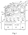
- the apparatus 10 comprises a printing section 12 disposed above a developing section 14.
- a digital image is written onto photosensitive material, and in developing section 14 the photosensitive material is developed such that when the print leaves the apparatus 10, a fully developed image is formed thereon.
- the printing section 12 preferably comprises an LED printing system such as described in copending application entitled “Method and Apparatus for Exposing Photosensitive Media with Multiple Light Sources", of Douglas H. Smith, John F. Carson, Roy F. Ference, and Karen J. Appel, U.S. Serial No. 08/123,839, filed September 20, 1993, and which is hereby incorporated by reference.
- the printing section 12 includes a rotary print system 16 which employs a digital multi-beam color exposure system, which is illustrated in greater detail in Figures 2 and 3.
- the printing system 16 includes a rotor 18 which is coupled to a drive motor (not shown) for rotating of the rotor 18 about longitudinal axis x-x.
- the rotor 18 is arranged to spin and move axially within a stationary cylindrical print shoe 20 which is provided with a sheet of photosensitive material 22.
- the photosensitive material 22 is provided in a continuous roll 24 contained in a magazine 26 and is cut to the desired length by cutter 27 disposed after shoe 20.
- a pair of guide rollers 28 is provided for guiding and driving of the photosensitive material 22 into the rotary print system.
- a pair of guide rollers 30 is provided in the print system 16 for guiding the photosensitive material to shoe 20.
- the photosensitive material 22 is wrapped on the inner surface 31 of the shoe 20.
- An another pair of guide rollers 32 is provided for guiding the photosensitive sheet of material out of the shoe 20.
- the photosensitive material is guided in the direction of the developing section 14 by guide 34.
- an appropriate vacuum system (not shown) is provided such that the photosensitive material 22 is securely and firmly held against the shoe for allowing writing of the image by rotor 18.
- this includes the providing of a plurality of small holes on the inner surface 31 of the shoe which is connected to a vacuum source.
- the vacuum source is turned on when the photosensitive material is in the printing position in the shoe 20 for printing and is turned off when the sheet is being transported into or out of the shoe.
- the rotor 18 is simultaneously rotated about axis x-x in a fast scan direction and is translated along the longitudinal axis x-x of the shoe 20.
- Rotor 18 is attached to a linear translation assembly comprising a pedestal structure 38, a translator base 40, and a leadscrew 42 driven by a stepper motor 44, with the leadscrew 42 being connected to the translator base by a coupler 46.
- a suitable coupler is described in further detail in copending application entitled "Leadscrew Coupler", of Bradley S. Jadrich and Mark E. Bridges, U.S. Serial No. 08/123,838, filed January 28, 1992, and which is also hereby incorporated by reference.
- the rotor 18 is simultaneously rotated by drive motor (not shown) in a fast scan direction and is translated past the stationary print shoe 20 in a slow scan actual direction x-x about by stepper motor 44, leadscrew 42, and coupling 46, thereby achieving a raster scan pattern on the photosensitive material being held within the shoe 20.
- An LED printhead assembly 48 is mounted in the rotor 18 and comprises a plurality of mono-colored light sources, such as an array of LEDs 48 (see Figure 3).
- the printhead assembly 48 is located within the body of the rotor 18, as illustrated in Figure 1, with the LED array package positioned so that the LED aperture output surface is located in a plane which is perpendicular to the optical axis of the projection lens assembly (not shown) for imaging onto the photosensitive material.
- the projection lens assembly is used to simultaneously image or focus all the LEDs onto a surface located in close proximity above the outer surface of the rotor, and more particularly, onto the surface of the photosensitive material 22 held by the shoe 20.
- a single lens thereby images or focuses the plurality of LEDs onto the photosensitive material 22 as a plurality of individual images which constitute the writing beam that exposes the image pixels.
- the LED array is arranged to provide a continuous-tone, full color image from a digital input signal.
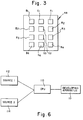
- the LED head assembly 48 (see Figure 3) comprises three columns of four LEDs; with each column comprised of a single color, with at least one of the rows having different colors than the other rows, and preferably, with one row each having one of red, green, and blue LEDs, respectively.
- the red LEDs are identified as R 1 , R 2 , R 3 , and R 4 ;
- the green LEDs are identified as G 1 , G 2 , G 3 , and G 4 ;
- the blue LEDs are identified as B 1 , B 2 , B 3 , and B 4 .
- the LED array is operated such that the desired color images are formed on the photosensitive material.
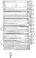
- the processing section 50 (as shown in Figure 1) comprises a plurality of processing modules 53,55,57a,57b,57c wherein a processing step occurs at each module.
- the photosensitive material is subjected to a developing solution at module 53, a bleach fixing solution at module 55, and a stabilizer solution at modules 57a,57b,57c.
- Each of the processing modules 53,55,57a,57b,57c utilizes a low volume thin channel/tank processing system.
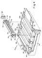
- the processing modules 53,55,57a,57b,57c each include a container 51 (see Figure 4); an upturned entrance channel 52; an entry transport roller assembly 54; at least one transport roller assembly 56; an exit transport roller assembly 58; an upturned exit channel 60; high impingement slot nozzle assemblies 62a,62b,62c; a drive 64; and-a rotating assembly 66.
- Assembly 66 may be any known means for turning drive 64, i.e. a motor, a gear, a belt, a chain, etc.
- Assemblies 54,56,58 are positioned within the container 51 in the vicinity of the walls of the container and slot nozzle assemblies 62a,62b,62c are positioned within the vicinity of the walls of the container.
- Transport roller assembly 56 includes a top roller 70; a bottom roller 72; tension springs 74, which holds top roller 70 in compression with respect to bottom roller 72; a bearing bracket 76; and slot nozzle assemblies 62a,62b,62c, each having a top channel section 78 and bottom channel section 79, which forms a thin low volume processing channel 80 through which the photosensitive material passes.
- the channel 80 in each nozzle assembly has openings 82 at either end for allowing processing solution to leave channel 80 and the photosensitive material 22 to pass through channel 80.
- a discharge opening (not shown), preferably in the form an elongated slot, is provided in the top and/or bottom channel sections 78,79 for allowing the processing solution supplied to each of the slot nozzle assemblies to be delivered to its respective processing channel.
- Rollers 70,72 may be drive or driven rollers and rollers 70,72 are connected to bearing bracket 76. Rollers 70,72 are rotated by intermeshing gears 84.
- the photosensitive material 22 is transported in a direction "A" automatically through processing channel 80 by roller assemblies 54,56,58.
- Cross-over assembly 68 is provided for assisting transporting the photosensitive material to the next adjacent processing module or processing step.
- FIG. 5 there is illustrated a partial cut-away section of a processing module which illustrates the openings 86 provided for supplying photosensitive processing solution from the recirculation system 89 (see Figure 1), as indicated by the arrows adjacent thereto, to the processing channel sections 78,79 for delivery of the processing solution to the processing channel 80. Exit passages 88 are provided for returning processing solution to the recirculation system 89.
- the recirculation system 89 includes separate means for recirculating the processing solution to each of the processing modules. Appropriate plumbing and connections (not shown) are also provided for connecting the replenishment section 90 to the recirculation system 89.
- Overflow effluent from the modules is passed onto effluent section 94, by appropriate plumbing, for proper retention or disposal.
- drying section 98 which includes a dryer 100 and dryer blower 102. After drying, the photosensitive material is passed onto a receiving tray 104.
- the processing section 50 is designed to be of the low volume type so that the processing solutions contained in each module will not age and, thus, will be used more efficiently.
- each processing module provides a small volume for holding processing solution in channel 80.
- processing channel 80 should have a thickness t preferably equal to or less than about 50 times the thickness of the photosensitive material being processed, preferably the thickness t is equal to or less than about 10 times the paper thickness.
- the thickness t of the processing channel 80 should be equal to or less than about 50 times the thickness of the paper being processed.
- thickness t is equal to or less than about 10 times the paper thickness.
- processors made in accordance with the present invention which processes paper having a thickness of about .008", would have a channel thickness t of about .08", and a processor which processes film having a thickness of about .005" would have a channel thickness t of about .10".
- the total volume of the processing solution within the processing channel 80 and recirculation system 89 for each module is relatively small as compared to prior art processors.
- the total amount of processing solution in the entire processing system for each of the modules is such that the total volume of the available channel 80 for holding processing solution is at least 40% of the total volume of processing solution available within the processing module and recirculation system.
- the volume of processing channel 80 is at least 50% of the total volume of the processing solution in the system. In the particular embodiment illustrated, the volume of the processing channel is about 60% of the total volume of the available processing solution.
- the amount of processing solution available in the system will vary on the size of the processor, that is, the amount of photosensitive material the processor is capable of processing, for example, a typical prior art microlab processor (a processor that processes up to about 5 ft 2 /min. of photosensitive material) which generally has a transport speed of less than about 50 in/min. (has about 17 liters of processing solution as compared to about 5 liters for a processor made in accordance with the present invention).
- a processor that processes from about 5 ft 2 /min. to about 15 ft 2 /min. of photosensitive material which generally has a transport speed from about 50 in/min.
- the discharge opening or openings in each of the slot nozzle assemblies that delivers processing solution to the processing channel have a configuration in accordance with the following relationship: 1 ⁇ F/A ⁇ 40 wherein: F is the flow rate of the solution through the nozzle in gallons per minute; and A is the cross-sectional area of the nozzle provided in square inches.
- the photosensitive material is preferably provided on a roll. This allows the production of various size prints.
- the length of the print may be any desired length which is limited by the length of the roll.
- the width of the images is limited by the width of the roll. Since the present invention employs a digital printer, a plurality of images may be placed in any format and various combinations on the photosensitive material in order to better utilize the photosensitive material being processed and thereby minimize waste of photosensitive material processed through the device.
- text and/or graphics can be added to the image to be printed. This additional text and/or graphics can be prestored in CPU 110 or can be added through CPU 110 (see Figure 6).
- the use of the shoe and rotating rotor into the printing section and the horizontal thin processing channel allows the use of a wide variety of different size photosensitive materials without any change in structure in the apparatus, thereby minimizing cost and/or any change-overs required to print different size photosensitive materials. Additionally, the structure of the present invention provides for a compact printer processor which does not take up very much room, and thus can be accommodated much more easily at a variety of commercial locations.
- An optional densitometer 107 may be provide adjacent the dryer exit and before the exit port 109 of the apparatus (see Figure 1).
- the densitometer 107 may be placed at any other convenient place after the development module.
- the densitometer 107 can be used to self-calibrate both the printing and processing section of the apparatus. Since the printer is digital, prestored calibration exposures can be stored in memory of the printer control computer (CPU) 116 of the apparatus 10. The calibration exposures can be printed when it is desired to check the operation of the apparatus 10. This can be done manually or automatically after a predetermined time period has passed or a certain number of images or photosensitive material has been processed.
- the densitometer 107 can be used to measure the calibration exposure printed and developed, the results of which can be passed on to control computer 106 (such as a CPU) used to run and operate the developing section of apparatus 10.
- control computer 106 such as a CPU
- the results can thus be analyzed and appropriate action taken by the apparatus to correct any inaccuracies, for example, used to readjust the replenishment rate of the replenishment solutions to the processor.
- this information can be used to control the amount of replenishment supplied to the module.
- the results could also be used to take corrective action in the printer in response to the aging of the LEDs. It is, of course, understood that any other desired or appropriate corrective action may also be taken. This feature would be very useful in a self-serve printing and processing apparatus where the operator will not be available to make the appropriate corrections or adjustments. Therefore, the present invention provides means for determining the operational effectiveness of various controllable operations.
- a central processing unit (CPU) 110 which is typically in the form of a personal computer, is provided to receive digital image record files from a plurality of digital sources 112,114.
- Sources 112,114 may be film scanners; flat bed scanners, computer files on floppy or portable hard disks, photo CDs, or other digital sources.
- An example of a suitable scanner is the Kodak Professional RFS 2035 scanner.
- the digital record file to be printed is forwarded from CPU 110 to the CPU 116 of the print section which is then forwarded to printhead assembly 48 (see Figure 1) for exposing photosensitive material 22.
- a modified developing section 14 including a modified processing section 50, dryer section 98, and a recirculation system 89 made in accordance with the present invention.
- like numerals represent like parts and operation as previously described.
- processing section 50 and dryer section 98.
- the dryer section 98 is positioned horizontally adjacent processing section 50, thus allowing the photosensitive material 22 to exit horizontally from the printing and processing apparatus through exit port 120.
- processing modules 153,155,157a,157b,157c are provided.
- Module 153 is a developing module which contains a developing processing solution for developing the photosensitive material;
- module 155 which contains a bleach fixing solution;
- modules 157a,157b,157c which contain stabilizer wash solutions.
- the level of the processing solutions in each of the modules is indicated generally by the letter "L" as shown in Figure 7.
- Each of the modules 153,155,157a,157b,157c are received in well sections 130,132,134,136,138 formed in container 140, respectively.
- the well sections are preferably integrally formed as a part of the container 140.
- the photosensitive material 22 enters the processing section 50 through opening 141 and is guided by guide roller assembly 142 having a pair of rollers 143, which passes the photosensitive material 22 through a nozzle assembly 144, which comprises an upper nozzle section 145 and a pair of lower nozzle sections 146a,146b.
- the upper and lower sections 145,146a,146b form a thin processing channel 147 for processing of the photosensitive material as it passes through the nozzle assembly 144.
- a pair of impingement slot nozzle openings 148 are provided in upper nozzle section 145, which are in alignment with a pair of slot nozzle openings 150 in lower nozzle sections 146a,146b.
- openings 148,150 each comprises a single elongated slot which extends across the width of the photosensitive material.
- the openings 148,150 may comprise a plurality of openings disposed adjacent each other in any desired pattern.
- the slot nozzle openings 148,150 provide for the impingement of a photoprocessing solution against the photosensitive material passing through the channel 147 of nozzle assembly 144.
- nozzle openings 148,150 are provided on both sides of the photosensitive material, only one of the slot nozzle openings 148,150, either in the top or bottom sections 145,146 may be provided so as to impinge the emulsion placed on either the top or bottom surface of the photosensitive material 22.
- a transport roller assembly 159 is provided for moving the photosensitive material 22 through nozzle assembly 144.
- Guide blocks 161, guide sections 163, and guide plates 165 provide a guide path for guiding the material 22.
- guide blocks 161 are separate components which are secured to processing modules, whereas guide sections 163 may be formed as a part of the container 140.
- the guide plates 165 are secured to the apparatus 10 in any desired manner.
- the cross-over assembly 154 is received in a well 160, sized and shaped so as to properly receive the cross-over assembly 154.
- Modules 153,155,157a,157b,157c are similarly constructed as is module 153, like numerals indicating like parts. The only difference being in these particular modules is there is only a single opening 148,150 for impingement of the processing solution against the photosensitive material for that particular module.
- a cross-over assembly 154 is provided between modules 153,155,157a,157b,157c and dryer section 98.
- the nozzle assemblies and transport assemblies are all designed so they can be easily lifted out of the container 140, thus allowing easy access to all of the individual modules.
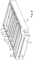
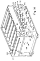
- the developing section 14, which includes the processing section 50, recirculation system 89, and dryer section 98 are mounted to apparatus 10 such that it can slide outward in the direction indicated by arrow 171 in Figure 10. This assists in providing easy access to the processing and dryer sections as required.
- Rotational drive power for each of the transport rollers and cross-over assemblies 142,152,154,159 comes from shaft 170, which is mechanically coupled to each of the roller assemblies by known gear means, which in the particular embodiment are worm gears 172,174,176,178,180,182,184,186,188, 190,192.
- gear means which in the particular embodiment are worm gears 172,174,176,178,180,182,184,186,188, 190,192.
- FIG. 10 there is illustrated a perspective view of the developing section 14 of apparatus 10, and more particularly illustrating the processing section 50, drying section 98 and recirculation system 89.
- a heat duct 194 receives heated air from the electrical control box 115, which contains the electronics for operating the developing section 14 which includes CPU 106, via fan 198.
- the duct 194 also contains the motor for the recirculation pumps (not shown) used in the recirculation system 89.
- the central box 115 is preferably isolated from the recirculating system and includes a plurality of openings (not shown) for allowing fresh air to enter.
- the processing solution is more subject to being affected by the ambient temperature and heat generated by the apparatus 10.
- the heat generated by the recirculation pumps, and other heat generating devices that are present are isolated from the recirculation system 89.
- the pump motors are isolated from the pump heads (impellers) 202a,202b,202c,202d,202e. Since the pump motors are located in duct 194, they are substantially isolated from the remaining portion of the recirculating system 89.
- Inlet openings 204a,204b,204c,204d,204e are provided in duct 194 for allowing fresh circulating air to enter the duct 194 adjacent the pump motors which combines with the heat from the control box 105 and is forwarded on to the dryer section 98 to supplement the drying heat and also evacuate excess heat that may be generated by the apparatus.
- a small fan (not shown) may be placed adjacent openings 204 for drawing fresh air in through openings 204 and blowing it across the recirculation pumps.
- appropriate filters are provided such that only filtered air enters duct 194 and is delivered to the drying section 98.
- the motors have fans built integrally therewith.
- heating elements are provided in section 206 which heats the air for delivery to dryer section 98 through openings 208 which is then conveyed to nozzle assemblies (not shown) in dryer section 98.
- the nozzles deliver the heated air between drive rollers 209 as indicated by arrows 212.
- a dryer blower (not shown) is provided adjacent opening 210 for delivering air to the heating element (not shown) provided in section 206.
- This fan is of sufficient size and capacity to overpower the direction of air flow indicated by arrow 205 when the processing section 50 is in the active operational mode.
- the air flow will come from the lower portion 211 of duct 194 through opening 210 up to dryer section 98 (as indicated by arrows 213 and 215) and impinged on the photosensitive material as indicated by arrows 212.
- Some of the drying air will exit opening 120 while the majority of the drying air will be recirculated back into duct 194 (as indicated by arrow 217) which is then drawn back through opening 210.
- the developing section may be modified so as be a stand alone low volume thin tank type processor having all of the benefits of isolating the heat generating devices from the recirculating system disclosed herein.
- the present invention provides a compact printing and processing apparatus wherein low volume utilization of photosensitive material can be provided without any significant effect to the chemistry therein. Also the apparatus can accommodate large sized prints and a wide variation in different widths and lengths of photosensitive materials while requiring a relatively small area. Additionally, the present invention provides an apparatus which is relatively inexpensive, reliable, easy to service, and produces high quality color images on photosensitive material.
Landscapes
- Engineering & Computer Science (AREA)
- Multimedia (AREA)
- Signal Processing (AREA)
- Physics & Mathematics (AREA)
- General Physics & Mathematics (AREA)
- Photographic Processing Devices Using Wet Methods (AREA)
Applications Claiming Priority (2)
| Application Number | Priority Date | Filing Date | Title |
|---|---|---|---|
| US383283 | 1995-02-03 | ||
| US08/383,283 US5739896A (en) | 1995-02-03 | 1995-02-03 | Method and apparatus for digitally printing and developing images onto photosensitive material |
Publications (3)
| Publication Number | Publication Date |
|---|---|
| EP0725530A2 true EP0725530A2 (fr) | 1996-08-07 |
| EP0725530A3 EP0725530A3 (fr) | 1997-08-20 |
| EP0725530B1 EP0725530B1 (fr) | 2002-07-03 |
Family
ID=23512449
Family Applications (1)
| Application Number | Title | Priority Date | Filing Date |
|---|---|---|---|
| EP96100252A Expired - Lifetime EP0725530B1 (fr) | 1995-02-03 | 1996-01-10 | Dispositif d'impression et de développement |
Country Status (6)
| Country | Link |
|---|---|
| US (1) | US5739896A (fr) |
| EP (1) | EP0725530B1 (fr) |
| JP (1) | JPH08248607A (fr) |
| AU (1) | AU698048B2 (fr) |
| DE (1) | DE69622057T2 (fr) |
| SG (1) | SG65546A1 (fr) |
Families Citing this family (8)
| Publication number | Priority date | Publication date | Assignee | Title |
|---|---|---|---|---|
| JP2811409B2 (ja) * | 1994-02-08 | 1998-10-15 | 西本産業株式会社 | 濃淡画像処理装置 |
| EP0980581A1 (fr) * | 1998-03-05 | 2000-02-23 | Fed Corporation | Photolithographie en bleu et en ultraviolet realisee a l'aide de dispositifs illuminants organiques |
| US6278511B1 (en) * | 1998-12-30 | 2001-08-21 | Agfa Corporation | Method and apparatus for stacking and drying cut imaged media |
| JP2000214561A (ja) * | 1999-01-20 | 2000-08-04 | Fuji Photo Film Co Ltd | 画像形成方法 |
| US6401360B1 (en) * | 2000-04-13 | 2002-06-11 | Eastman Kodak Company | Apparatus and method for drying photosensitive material using a radiant heat assembly |
| US6290404B1 (en) * | 2000-11-03 | 2001-09-18 | Eastman Kodak Company | Processing system and method which includes heat recovery and reuse in a photographic processing machine |
| US6911379B2 (en) * | 2003-03-05 | 2005-06-28 | Taiwan Semiconductor Manufacturing Company, Ltd. | Method of forming strained silicon on insulator substrate |
| ES2598004B1 (es) * | 2015-06-24 | 2017-12-12 | Pablo IBAÑEZ RAZOLA | Máquina compacta híbrida digital-analógica de revelado |
Family Cites Families (48)
| Publication number | Priority date | Publication date | Assignee | Title |
|---|---|---|---|---|
| US3372630A (en) * | 1965-06-04 | 1968-03-12 | Houston Schmidt Ltd | Apparatus for processing light sensitive film |
| US3475093A (en) * | 1967-01-25 | 1969-10-28 | Dick Co Ab | Feed mechanism for photocopy machine or the like |
| US3922701A (en) * | 1972-09-02 | 1975-11-25 | Agfa Gevaert Ag | Apparatus for processing photographic films |
| JPS5346092B2 (fr) * | 1973-03-07 | 1978-12-11 | ||
| IT1027090B (it) * | 1973-12-20 | 1978-11-20 | Duerr Dental Kg | Sviluppatrice per pellicole radio grafiche |
| JPS5459928A (en) * | 1977-10-21 | 1979-05-15 | Fuji Photo Film Co Ltd | Camera processor |
| JPS5651743A (en) * | 1979-10-04 | 1981-05-09 | Dainippon Screen Mfg Co Ltd | Method for deciding optimal replenishing amount of developing solution in film developing machine |
| DE3220169A1 (de) * | 1982-05-28 | 1983-12-01 | Agfa-Gevaert Ag, 5090 Leverkusen | Nachdosiereinrichtung in einer mit einem fotosatz in verbindung stehenden fotografischen entwicklungsmaschine |
| US4716285A (en) * | 1984-08-23 | 1987-12-29 | Fuji Photo Film Co., Ltd. | Light amount correction method and apparatus for image output system |
| US4723151A (en) * | 1985-09-20 | 1988-02-02 | Fuji Photo Film Co., Ltd. | Image recording and developing apparatus |
| JPS62108254A (ja) * | 1985-11-05 | 1987-05-19 | Konishiroku Photo Ind Co Ltd | 画像形成装置 |
| JPH0612436B2 (ja) * | 1985-11-05 | 1994-02-16 | コニカ株式会社 | 感光材料処理装置 |
| US4698647A (en) * | 1986-05-13 | 1987-10-06 | Truvel Corporation | High resolution photographic film printer |
| US4791444A (en) * | 1986-06-04 | 1988-12-13 | Fuji Photo Film Co., Ltd. | Waste solution treating apparatus |
| US4757334A (en) * | 1986-12-09 | 1988-07-12 | Ivan Volent | System for density correction of medical imaging film hard copy |
| US4881095A (en) * | 1987-09-11 | 1989-11-14 | Fuji Photo Film Co., Ltd. | Process for developing photographed film and for printing images through developed film |
| US4816846A (en) * | 1987-12-17 | 1989-03-28 | American Telephone And Telegraph Company, At&T Bell Laboratories | Method and apparatus for direct color printing |
| JPH02100050A (ja) * | 1988-10-07 | 1990-04-12 | Fuji Photo Film Co Ltd | 感光材料乾燥装置 |
| US5070351A (en) * | 1989-10-13 | 1991-12-03 | E. I. Du Pont De Nemours And Company | Method and apparatus for processing photosensitive material |
| GB9003282D0 (en) * | 1990-02-14 | 1990-04-11 | Kodak Ltd | Method and apparatus for photographic processing |
| GB9012860D0 (en) * | 1990-06-08 | 1990-08-01 | Kodak Ltd | Photographic processing tank |
| GB9022781D0 (en) * | 1990-10-19 | 1990-12-05 | Kodak Ltd | Photographic processing apparatus |
| GB9022779D0 (en) * | 1990-10-19 | 1990-12-05 | Kodak Ltd | Photographic processing apparatus |
| GB9025598D0 (en) * | 1990-11-24 | 1991-01-09 | Kodak Ltd | Photographic processing apparatus |
| US5146257A (en) * | 1991-02-19 | 1992-09-08 | Minnesota Mining And Manufacturing Company | Developer solution replenishment control system for a digital imaging system |
| GB9106439D0 (en) * | 1991-03-26 | 1991-05-15 | Kodak Ltd | Photographic processing apparatus |
| GB9114090D0 (en) * | 1991-06-29 | 1991-08-14 | Kodak Ltd | Photographic processing apparatus |
| JPH0514655A (ja) * | 1991-07-02 | 1993-01-22 | Brother Ind Ltd | 画像記録装置 |
| GB9203546D0 (en) * | 1992-02-20 | 1992-04-08 | Kodak Ltd | A fluid dispenser and apparatus for dispensing fluid |
| US5309191A (en) * | 1992-03-02 | 1994-05-03 | Eastman Kodak Company | Recirculation, replenishment, refresh, recharge and backflush for a photographic processing apparatus |
| US5311235A (en) * | 1992-03-02 | 1994-05-10 | Eastman Kodak Company | Driving mechanism for a photographic processing apparatus |
| US5179404A (en) * | 1992-03-02 | 1993-01-12 | Eastman Kodak Company | Anti-web adhering contour surface for a photographic processing apparatus |
| US5270762A (en) * | 1992-03-02 | 1993-12-14 | Eastman Kodak Company | Slot impingement for a photographic processing apparatus |
| JPH05289299A (ja) * | 1992-04-14 | 1993-11-05 | Konica Corp | 自動現像機 |
| JPH06141166A (ja) * | 1992-10-22 | 1994-05-20 | Ricoh Co Ltd | ディジタル複写機 |
| US5452043A (en) * | 1993-02-19 | 1995-09-19 | Eastman Kodak Company | Rack and a tank for a photographic low volume thin tank insert for a rack and a tank photographic processing apparatus |
| JP2906902B2 (ja) * | 1993-03-10 | 1999-06-21 | ノーリツ鋼機株式会社 | 画像焼付方法及び装置 |
| US5353086A (en) * | 1993-05-03 | 1994-10-04 | Eastman Kodak Company | Textured surface with canted channels for an automatic tray processor |
| US5355190A (en) * | 1993-05-03 | 1994-10-11 | Eastman Kodak Company | Slot impingement for an automatic tray processor |
| US5386261A (en) * | 1993-05-03 | 1995-01-31 | Eastman Kodak Company | Vertical and horizontal positioning and coupling of automatic tray processor cells |
| US5347337A (en) * | 1993-05-03 | 1994-09-13 | Eastman Kodak Company | Vertical and horizontal positioning and coupling of automatic tray processor cells |
| US5313243A (en) * | 1993-05-03 | 1994-05-17 | Eastman Kodak Company | Counter cross flow for an automatic tray processor |
| US5353083A (en) * | 1993-05-03 | 1994-10-04 | Eastman Kodak Company | Closed solution recirculation/shutoff system for an automatic tray processor |
| US5389994A (en) * | 1993-05-03 | 1995-02-14 | Eastman Kodak Company | Closed solution recirculation/shutoff system for an automatic tray processor |
| US5353087A (en) * | 1993-05-03 | 1994-10-04 | Eastman Kodak Company | Automatic replenishment, calibration and metering system for an automatic tray processor |
| US5339131A (en) * | 1993-05-03 | 1994-08-16 | Eastman Kodak Company | Automatic replenishment, calibration and metering system for a photographic processing apparatus |
| US5381203A (en) * | 1993-05-03 | 1995-01-10 | Eastman Kodak Company | Textured surface with canted channels for an automatic tray processor |
| US5353088A (en) * | 1993-05-03 | 1994-10-04 | Eastman Kodak Company | Automatic tray processor |
-
1995
- 1995-02-03 US US08/383,283 patent/US5739896A/en not_active Expired - Fee Related
-
1996
- 1996-01-10 EP EP96100252A patent/EP0725530B1/fr not_active Expired - Lifetime
- 1996-01-10 DE DE69622057T patent/DE69622057T2/de not_active Expired - Fee Related
- 1996-02-02 AU AU42293/96A patent/AU698048B2/en not_active Ceased
- 1996-02-03 SG SG1996000885A patent/SG65546A1/en unknown
- 1996-02-05 JP JP8018674A patent/JPH08248607A/ja active Pending
Also Published As
| Publication number | Publication date |
|---|---|
| EP0725530B1 (fr) | 2002-07-03 |
| US5739896A (en) | 1998-04-14 |
| EP0725530A3 (fr) | 1997-08-20 |
| SG65546A1 (en) | 1999-06-22 |
| DE69622057T2 (de) | 2003-01-30 |
| AU698048B2 (en) | 1998-10-22 |
| AU4229396A (en) | 1996-08-15 |
| JPH08248607A (ja) | 1996-09-27 |
| DE69622057D1 (de) | 2002-08-08 |
Similar Documents
| Publication | Publication Date | Title |
|---|---|---|
| JP3417516B2 (ja) | カセット式電子画像焼付装置と写真処理装置及びこれらの装置を用いた写真処理システム | |
| US5452050A (en) | Image printer | |
| US5739896A (en) | Method and apparatus for digitally printing and developing images onto photosensitive material | |
| JPH11174648A (ja) | 感光材料処理装置 | |
| JP4056590B2 (ja) | 画像記録装置 | |
| JP3597342B2 (ja) | 画像記録装置 | |
| US7029188B2 (en) | Image forming apparatus, image forming apparatus setup system, and image forming apparatus setup method | |
| US6229594B1 (en) | Photosensitive material scan-exposure method and photosensitive material exposure apparatus | |
| US6624875B2 (en) | Image recording device | |
| JP2962482B2 (ja) | 感光材料処理装置 | |
| JP3585138B2 (ja) | 感光材料処理装置 | |
| KR100199037B1 (ko) | 사진처리장치 | |
| JP3753519B2 (ja) | 画像記録装置 | |
| JPH10333253A (ja) | 画像記録装置 | |
| US6072563A (en) | Printer apparatus for simultaneously printing multiple images | |
| JPH10333313A (ja) | 画像記録装置 | |
| JPH1013595A (ja) | 画像記録装置 | |
| JPH11305356A (ja) | 投影焼付装置及び投影焼付装置の制御情報を得る方法 | |
| JPH11194433A (ja) | 画像記録装置 | |
| JPH10171034A (ja) | 画像読取再生装置 | |
| JPH10293364A (ja) | 画像記録装置 | |
| JPH10197963A (ja) | 画像記録装置 | |
| JP2002062596A (ja) | デジタル写真処理装置 | |
| JPH10177244A (ja) | 感光材料処理装置 | |
| JP2007178571A (ja) | 現像処理装置 |
Legal Events
| Date | Code | Title | Description |
|---|---|---|---|
| PUAI | Public reference made under article 153(3) epc to a published international application that has entered the european phase |
Free format text: ORIGINAL CODE: 0009012 |
|
| AK | Designated contracting states |
Kind code of ref document: A2 Designated state(s): CH DE FR GB IT LI |
|
| PUAL | Search report despatched |
Free format text: ORIGINAL CODE: 0009013 |
|
| AK | Designated contracting states |
Kind code of ref document: A3 Designated state(s): CH DE FR GB IT LI |
|
| 17P | Request for examination filed |
Effective date: 19980126 |
|
| 17Q | First examination report despatched |
Effective date: 19991230 |
|
| GRAG | Despatch of communication of intention to grant |
Free format text: ORIGINAL CODE: EPIDOS AGRA |
|
| GRAG | Despatch of communication of intention to grant |
Free format text: ORIGINAL CODE: EPIDOS AGRA |
|
| GRAH | Despatch of communication of intention to grant a patent |
Free format text: ORIGINAL CODE: EPIDOS IGRA |
|
| GRAH | Despatch of communication of intention to grant a patent |
Free format text: ORIGINAL CODE: EPIDOS IGRA |
|
| GRAA | (expected) grant |
Free format text: ORIGINAL CODE: 0009210 |
|
| AK | Designated contracting states |
Kind code of ref document: B1 Designated state(s): CH DE FR GB IT LI |
|
| REG | Reference to a national code |
Ref country code: CH Ref legal event code: EP |
|
| REF | Corresponds to: |
Ref document number: 69622057 Country of ref document: DE Date of ref document: 20020808 |
|
| REG | Reference to a national code |
Ref country code: CH Ref legal event code: NV Representative=s name: KIRKER & CIE SA |
|
| ET | Fr: translation filed | ||
| PLBE | No opposition filed within time limit |
Free format text: ORIGINAL CODE: 0009261 |
|
| STAA | Information on the status of an ep patent application or granted ep patent |
Free format text: STATUS: NO OPPOSITION FILED WITHIN TIME LIMIT |
|
| 26N | No opposition filed |
Effective date: 20030404 |
|
| PGFP | Annual fee paid to national office [announced via postgrant information from national office to epo] |
Ref country code: GB Payment date: 20041210 Year of fee payment: 10 |
|
| PGFP | Annual fee paid to national office [announced via postgrant information from national office to epo] |
Ref country code: FR Payment date: 20050105 Year of fee payment: 10 |
|
| PGFP | Annual fee paid to national office [announced via postgrant information from national office to epo] |
Ref country code: DE Payment date: 20050131 Year of fee payment: 10 |
|
| PGFP | Annual fee paid to national office [announced via postgrant information from national office to epo] |
Ref country code: CH Payment date: 20050317 Year of fee payment: 10 |
|
| PG25 | Lapsed in a contracting state [announced via postgrant information from national office to epo] |
Ref country code: GB Free format text: LAPSE BECAUSE OF NON-PAYMENT OF DUE FEES Effective date: 20060110 |
|
| PG25 | Lapsed in a contracting state [announced via postgrant information from national office to epo] |
Ref country code: LI Free format text: LAPSE BECAUSE OF NON-PAYMENT OF DUE FEES Effective date: 20060131 Ref country code: FR Free format text: LAPSE BECAUSE OF NON-PAYMENT OF DUE FEES Effective date: 20060131 Ref country code: CH Free format text: LAPSE BECAUSE OF NON-PAYMENT OF DUE FEES Effective date: 20060131 |
|
| PGFP | Annual fee paid to national office [announced via postgrant information from national office to epo] |
Ref country code: IT Payment date: 20060131 Year of fee payment: 11 |
|
| PG25 | Lapsed in a contracting state [announced via postgrant information from national office to epo] |
Ref country code: DE Free format text: LAPSE BECAUSE OF NON-PAYMENT OF DUE FEES Effective date: 20060801 |
|
| REG | Reference to a national code |
Ref country code: CH Ref legal event code: PL |
|
| GBPC | Gb: european patent ceased through non-payment of renewal fee |
Effective date: 20060110 |
|
| REG | Reference to a national code |
Ref country code: FR Ref legal event code: ST Effective date: 20060929 |
|
| PG25 | Lapsed in a contracting state [announced via postgrant information from national office to epo] |
Ref country code: IT Free format text: LAPSE BECAUSE OF NON-PAYMENT OF DUE FEES Effective date: 20070110 |