EP0733751A1 - Plaque à joints - Google Patents
Plaque à joints Download PDFInfo
- Publication number
- EP0733751A1 EP0733751A1 EP96100297A EP96100297A EP0733751A1 EP 0733751 A1 EP0733751 A1 EP 0733751A1 EP 96100297 A EP96100297 A EP 96100297A EP 96100297 A EP96100297 A EP 96100297A EP 0733751 A1 EP0733751 A1 EP 0733751A1
- Authority
- EP
- European Patent Office
- Prior art keywords
- joint plate
- sleeve
- opening
- projection
- plate according
- Prior art date
- Legal status (The legal status is an assumption and is not a legal conclusion. Google has not performed a legal analysis and makes no representation as to the accuracy of the status listed.)
- Granted
Links
- 239000000463 material Substances 0.000 claims abstract description 12
- 239000003063 flame retardant Substances 0.000 claims description 8
- 238000004519 manufacturing process Methods 0.000 claims description 4
- 239000002984 plastic foam Substances 0.000 claims description 2
- 239000011358 absorbing material Substances 0.000 claims 1
- 229920002457 flexible plastic Polymers 0.000 claims 1
- 239000006260 foam Substances 0.000 abstract description 2
- 239000004033 plastic Substances 0.000 abstract description 2
- 229920003023 plastic Polymers 0.000 abstract description 2
- 238000009413 insulation Methods 0.000 description 9
- 238000010276 construction Methods 0.000 description 4
- 238000011065 in-situ storage Methods 0.000 description 2
- 239000012774 insulation material Substances 0.000 description 2
- NJPPVKZQTLUDBO-UHFFFAOYSA-N novaluron Chemical compound C1=C(Cl)C(OC(F)(F)C(OC(F)(F)F)F)=CC=C1NC(=O)NC(=O)C1=C(F)C=CC=C1F NJPPVKZQTLUDBO-UHFFFAOYSA-N 0.000 description 2
- 239000000853 adhesive Substances 0.000 description 1
- 238000004026 adhesive bonding Methods 0.000 description 1
- 230000001070 adhesive effect Effects 0.000 description 1
- 239000002390 adhesive tape Substances 0.000 description 1
- 238000004873 anchoring Methods 0.000 description 1
- 230000005540 biological transmission Effects 0.000 description 1
- 230000006866 deterioration Effects 0.000 description 1
- 238000005516 engineering process Methods 0.000 description 1
- 230000009970 fire resistant effect Effects 0.000 description 1
- 238000009415 formwork Methods 0.000 description 1
- 230000001771 impaired effect Effects 0.000 description 1
- 239000007788 liquid Substances 0.000 description 1
- 239000002184 metal Substances 0.000 description 1
- 239000011490 mineral wool Substances 0.000 description 1
- 230000002093 peripheral effect Effects 0.000 description 1
- 239000011505 plaster Substances 0.000 description 1
- 239000011819 refractory material Substances 0.000 description 1
- 230000000717 retained effect Effects 0.000 description 1
- 238000003860 storage Methods 0.000 description 1
- 239000006228 supernatant Substances 0.000 description 1
- 230000007704 transition Effects 0.000 description 1
Images

Classifications
-
- E—FIXED CONSTRUCTIONS
- E04—BUILDING
- E04F—FINISHING WORK ON BUILDINGS, e.g. STAIRS, FLOORS
- E04F11/00—Stairways, ramps, or like structures; Balustrades; Handrails
- E04F11/02—Stairways; Layouts thereof
- E04F11/022—Stairways; Layouts thereof characterised by the supporting structure
-
- E—FIXED CONSTRUCTIONS
- E04—BUILDING
- E04B—GENERAL BUILDING CONSTRUCTIONS; WALLS, e.g. PARTITIONS; ROOFS; FLOORS; CEILINGS; INSULATION OR OTHER PROTECTION OF BUILDINGS
- E04B1/00—Constructions in general; Structures which are not restricted either to walls, e.g. partitions, or floors or ceilings or roofs
- E04B1/38—Connections for building structures in general
- E04B1/48—Dowels, i.e. members adapted to penetrate the surfaces of two parts and to take the shear stresses
- E04B1/483—Shear dowels to be embedded in concrete
-
- E—FIXED CONSTRUCTIONS
- E04—BUILDING
- E04B—GENERAL BUILDING CONSTRUCTIONS; WALLS, e.g. PARTITIONS; ROOFS; FLOORS; CEILINGS; INSULATION OR OTHER PROTECTION OF BUILDINGS
- E04B1/00—Constructions in general; Structures which are not restricted either to walls, e.g. partitions, or floors or ceilings or roofs
- E04B1/62—Insulation or other protection; Elements or use of specified material therefor
- E04B1/74—Heat, sound or noise insulation, absorption, or reflection; Other building methods affording favourable thermal or acoustical conditions, e.g. accumulating of heat within walls
- E04B1/82—Heat, sound or noise insulation, absorption, or reflection; Other building methods affording favourable thermal or acoustical conditions, e.g. accumulating of heat within walls specifically with respect to sound only
-
- E—FIXED CONSTRUCTIONS
- E04—BUILDING
- E04B—GENERAL BUILDING CONSTRUCTIONS; WALLS, e.g. PARTITIONS; ROOFS; FLOORS; CEILINGS; INSULATION OR OTHER PROTECTION OF BUILDINGS
- E04B1/00—Constructions in general; Structures which are not restricted either to walls, e.g. partitions, or floors or ceilings or roofs
- E04B1/62—Insulation or other protection; Elements or use of specified material therefor
- E04B1/92—Protection against other undesired influences or dangers
- E04B1/94—Protection against other undesired influences or dangers against fire
- E04B1/948—Fire-proof sealings or joints
-
- E—FIXED CONSTRUCTIONS
- E04—BUILDING
- E04B—GENERAL BUILDING CONSTRUCTIONS; WALLS, e.g. PARTITIONS; ROOFS; FLOORS; CEILINGS; INSULATION OR OTHER PROTECTION OF BUILDINGS
- E04B1/00—Constructions in general; Structures which are not restricted either to walls, e.g. partitions, or floors or ceilings or roofs
- E04B1/62—Insulation or other protection; Elements or use of specified material therefor
- E04B1/74—Heat, sound or noise insulation, absorption, or reflection; Other building methods affording favourable thermal or acoustical conditions, e.g. accumulating of heat within walls
- E04B1/82—Heat, sound or noise insulation, absorption, or reflection; Other building methods affording favourable thermal or acoustical conditions, e.g. accumulating of heat within walls specifically with respect to sound only
- E04B2001/8254—Soundproof supporting of building elements, e.g. stairs, floor slabs or beams, on a structure
Definitions
- the invention relates to a joint plate for, in particular, sound-insulating spacing of components such as stairs, walls and the like, which are connected to one another via projections, wherein at least one opening is provided in the joint plate for the passage of one component and into a corresponding recess in the other component extending projection.
- Joint plates of this type are installed, for example, between stairs and stair landings in order to prevent impact sound transmission between the two components.
- the joint plate made of, in particular, plastic flexible foam or other sound insulation material must have openings for the passage of the projections, which - depending on the material - can already be cut out of the joint plate by the manufacturer or only at the construction site.
- the present invention has for its object to improve the joint plate of the type described and to open it up for other applications. At the same time, it should be easy to use.
- the opening of the joint plate is larger than the cross section of the projection, that a sleeve is arranged in the opening, which adjoins the joint plate, that this sleeve has a push-through opening for the projection, the size of which is approximately corresponds to the cross section of the projection, and that the sleeve is made of fire-retardant material.
- the spacing of the projection and joint plate due to the sleeve according to the invention results in the advantage that in the event of a fire in the region of the joint, the projections are still reliably protected against fire and heat when the joint plate itself has already been destroyed.
- the function of the protrusions for example the lateral force bearing of the two adjacent components, is reliably guaranteed, while in the prior art the unprotected protrusions are destroyed and therefore usually not only the storage but also the adjacent components must be replaced.
- the present invention allows the fire protection area to be limited to the area around the projections and the area of the remaining joint plate only with a view to optimal ones Select sound insulation properties, for what purpose, for example Soft plastic foam recommends. In this way, costs and processing effort can be saved, since the proportion of the expensive and difficult to handle fire protection material is drastically reduced, while the soundproofing properties of the joint plate are retained.
- the sleeve be glued to the joint plate, which can be done on the one hand by gluing the respective abutting edges or on the other hand with the aid of adhesive strips which are applied laterally to the transition areas between the joint plate and the sleeve arranged flush with it.
- the sleeve can, however, also be welded into the joint plate or be connected in one piece with it in any way, in which case a seamless connection of both elements is recommended in order not to impair the sound insulation properties.
- the joint plate also acts as a lost formwork element, namely if one of the adjacent components is made of in-situ concrete. If the sleeve were only spaced from the joint plate in some areas, there would be the possibility that liquid concrete would flow into these gaps and create a sound connection between the two adjacent components.
- the sleeve can be made somewhat thinner than the joint plate in order to create an air gap for sound insulation; optimal sound insulation is achieved, in particular, if the fire-retardant material of the cuff itself has good sound insulation properties and is, for example, softly elastic, for which fire-resistant mineral wool is particularly recommended.
- the joint plates In addition to the possibility of manufacturing the joint plate with a sleeve by the manufacturer and thus automatically, the joint plates then having to be positioned on the construction site so that the prefabricated openings come to lie in the area of the projections, the openings can be cut out and the sleeves inserted of course, only take place at the construction site, so that the joint plate can be positioned freely without having to take into account prefabricated openings. So that such a construction-side production of the openings does not lead to a loss of quality of the joint plate, it is particularly advantageous if the joint plate has predetermined breaking points in the form of lines weakened cross-section for the production of openings adapted to the position of the projections.
- the opening which fits the size and position of the respective projection can be selected and separated from the predetermined breaking points which are expediently distributed in a grid-like manner over the surface of the joint plate.
- the other predetermined breaking points remain unused, so that the sound insulation properties are not impaired.
- the joint plate in the upper, lower and / or lateral border area of the adjacent components has a supernatant. This protrusion thus replaces any insulation strips that would otherwise have to be used for sound decoupling of the elements to be applied, or facilitates the connection of further insulation materials.
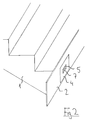
- a joint plate 2 lies flat.
- This joint plate 2 has a rectangular opening 3, into which a sleeve 4 made of fire-retardant material is molded.
- This sleeve lies with its peripheral edges flush against the opening edges of the joint plate 2, so that both parts form a continuous flat surface.
- a push-through opening 5 is provided, through which a transverse force mandrel 6 extending from the stair component 1 extends.
- This shear force mandrel 6 consists of a metal rectangular profile and is concreted into the stair component 1 or inserted into a recess (sleeve) concreted into the stair component, while its protruding end, after passing through the passage opening 5, is used for anchoring in a corresponding recess of the stair platform, not shown, so that the mandrel transfers lateral forces from the stair component to the stair landing.
- the size of the passage opening 5 is expediently chosen to be a few millimeters smaller than the cross section of the transverse force mandrel 6, as a result of which an all-round tight system is ensured along the circumference and thereby the transverse force mandrel is reliably protected by the fire-retardant material.
- Figure 2 shows the same joint plate without transverse force mandrel.
- a recess 7 is provided in the stair component, which is arranged congruently behind the passage opening 5 and into which the transverse force mandrel is then inserted.
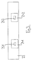
- FIG. 3 shows a joint plate 22 with two sleeves 241 and 242.
- the provision of two sleeves in a joint plate is relevant in such cases when standardized components with predetermined positions are used for the projections.
- Both sleeves 241 and 242 in turn have two rectangular through openings 251 and 252 and are connected without gaps to the joint plate 22 surrounding them.
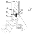
- FIG. 4 shows a joint plate 32 in the installed state between a stair component 31 and an adjoining stair platform 38.
- at least one sleeve 34 is formed in the joint plate 32 with a push-through opening 35 through which a transverse force mandrel 36 extends from the stair landing 38 into the adjacent stair component 31.
- the mandrel is sound-absorbing in a sleeve in the stair component 31.
- the joint plate 32 is formed with an upper and lower overhang which extends over the adjacent area of the stair component and the stair landing.
- the layers applied to the stair landing such as screed, floor covering, insulation and the like, are also decoupled from the neighboring stair component 31 in terms of sound technology.
- the present invention has the advantage that the projections are protected even in emergencies such as fires or the like and can safely perform their corresponding function while at the same time reducing the cost and labor involved in processing and assembling the joint plate.
Landscapes
- Engineering & Computer Science (AREA)
- Architecture (AREA)
- Physics & Mathematics (AREA)
- Civil Engineering (AREA)
- Structural Engineering (AREA)
- Electromagnetism (AREA)
- Acoustics & Sound (AREA)
- Polishing Bodies And Polishing Tools (AREA)
- Table Devices Or Equipment (AREA)
- Building Environments (AREA)
- Steps, Ramps, And Handrails (AREA)
Applications Claiming Priority (2)
| Application Number | Priority Date | Filing Date | Title |
|---|---|---|---|
| DE29504707U | 1995-03-24 | ||
| DE29504707U DE29504707U1 (de) | 1995-03-24 | 1995-03-24 | Fugenplatte |
Publications (2)
| Publication Number | Publication Date |
|---|---|
| EP0733751A1 true EP0733751A1 (fr) | 1996-09-25 |
| EP0733751B1 EP0733751B1 (fr) | 2000-05-10 |
Family
ID=8005595
Family Applications (1)
| Application Number | Title | Priority Date | Filing Date |
|---|---|---|---|
| EP96100297A Expired - Lifetime EP0733751B1 (fr) | 1995-03-24 | 1996-01-11 | Plaque à joints |
Country Status (3)
| Country | Link |
|---|---|
| EP (1) | EP0733751B1 (fr) |
| AT (1) | ATE192808T1 (fr) |
| DE (3) | DE29504707U1 (fr) |
Cited By (1)
| Publication number | Priority date | Publication date | Assignee | Title |
|---|---|---|---|---|
| CN109025291A (zh) * | 2018-07-25 | 2018-12-18 | 中国十七冶集团有限公司 | 一种分离式预制楼梯的施工方法 |
Families Citing this family (5)
| Publication number | Priority date | Publication date | Assignee | Title |
|---|---|---|---|---|
| DE29504707U1 (de) * | 1995-03-24 | 1995-05-04 | Schöck Bauteile GmbH, 76534 Baden-Baden | Fugenplatte |
| DE19600035C2 (de) * | 1996-01-02 | 1999-05-12 | Mea Meisinger Stahl & Kunststo | Verbindungseinrichtung zur Montage eines getragenen Gebäudeteils an ein tragendes Gebäudeteil |
| DE102005040170A1 (de) | 2005-08-25 | 2007-03-01 | Schöck Bauteile GmbH | Bauelement zur Wärme- und/oder Schalldämmung |
| DE102013100356A1 (de) * | 2013-01-14 | 2014-07-17 | Schöck Bauteile GmbH | Vorrichtung zum kraftübertragenden Verbinden eines ersten tragenden Gebäudeteils mit einem zweiten getragenen Gebäudeteil |
| NO337777B1 (no) * | 2014-03-03 | 2016-06-20 | Svein Berg Holding As | En jordskjelvbestandig bygningsforbindelse og et jordskjelvbestandig trappesystem. |
Citations (3)
| Publication number | Priority date | Publication date | Assignee | Title |
|---|---|---|---|---|
| DE3408556A1 (de) * | 1984-03-08 | 1985-09-12 | Eberhard Ing.(grad.) 7570 Baden-Baden Schöck | Trennelement fuer betonplatten |
| EP0116557B1 (fr) * | 1982-05-03 | 1986-08-27 | Vm Permaban Ab | Procede de positionnement de joint de dilatation lors de la coulee d'une dalle de beton |
| US4834576A (en) * | 1987-12-24 | 1989-05-30 | Settimio Argento | Expansion joint and form for concrete floors |
Family Cites Families (10)
| Publication number | Priority date | Publication date | Assignee | Title |
|---|---|---|---|---|
| DE3531441C2 (de) * | 1985-09-03 | 1996-06-13 | Eberhard Schoeck | Konsolelement zur Übertragung vertikaler Kräfte in Gebäuden |
| DE8621595U1 (de) * | 1986-08-12 | 1986-10-23 | GLT Gleit- und Lagertechnik GmbH, 5620 Velbert | Treppenlager |
| DE3744016C2 (de) * | 1987-12-24 | 1996-06-20 | Schoeck Bauteile Gmbh | Fugenplatte für Trennfugen an Gebäuden |
| DE4204084C1 (en) * | 1992-02-12 | 1993-05-27 | Dieter Dipl.-Ing. 4400 Muenster-Nienberge De Prior | Arrangement for damping sound of steps in stairwell - includes steel rails having L=shaped oscillating damping members |
| DE4211762A1 (de) * | 1992-04-08 | 1993-10-14 | Chemie Linz Deutschland | Intumeszierende, schwerbrennbare oder nichtbrennbare Schaumstoffprofile |
| DE4319632A1 (de) * | 1993-05-06 | 1994-11-10 | Ewald Wachsmann | Auflagerelement für Bauelemente |
| DE9310222U1 (de) * | 1993-07-09 | 1994-11-10 | Illbruck Gmbh, 51381 Leverkusen | Fugen-Brandschutzelement |
| DE4409477A1 (de) * | 1994-03-19 | 1995-09-21 | Schoeck Bauteile Gmbh | Trittschalldämmendes Auflagerelement |
| DE4429605A1 (de) * | 1994-08-20 | 1996-02-22 | Schoeck Bauteile Gmbh | Trittschalldämmendes Auflagerelement |
| DE29504707U1 (de) * | 1995-03-24 | 1995-05-04 | Schöck Bauteile GmbH, 76534 Baden-Baden | Fugenplatte |
-
1995
- 1995-03-24 DE DE29504707U patent/DE29504707U1/de not_active Expired - Lifetime
-
1996
- 1996-01-11 AT AT96100297T patent/ATE192808T1/de not_active IP Right Cessation
- 1996-01-11 EP EP96100297A patent/EP0733751B1/fr not_active Expired - Lifetime
- 1996-01-11 DE DE59605157T patent/DE59605157D1/de not_active Expired - Fee Related
- 1996-03-21 DE DE29605209U patent/DE29605209U1/de not_active Expired - Lifetime
Patent Citations (3)
| Publication number | Priority date | Publication date | Assignee | Title |
|---|---|---|---|---|
| EP0116557B1 (fr) * | 1982-05-03 | 1986-08-27 | Vm Permaban Ab | Procede de positionnement de joint de dilatation lors de la coulee d'une dalle de beton |
| DE3408556A1 (de) * | 1984-03-08 | 1985-09-12 | Eberhard Ing.(grad.) 7570 Baden-Baden Schöck | Trennelement fuer betonplatten |
| US4834576A (en) * | 1987-12-24 | 1989-05-30 | Settimio Argento | Expansion joint and form for concrete floors |
Cited By (1)
| Publication number | Priority date | Publication date | Assignee | Title |
|---|---|---|---|---|
| CN109025291A (zh) * | 2018-07-25 | 2018-12-18 | 中国十七冶集团有限公司 | 一种分离式预制楼梯的施工方法 |
Also Published As
| Publication number | Publication date |
|---|---|
| DE59605157D1 (de) | 2000-06-15 |
| ATE192808T1 (de) | 2000-05-15 |
| DE29504707U1 (de) | 1995-05-04 |
| EP0733751B1 (fr) | 2000-05-10 |
| DE29605209U1 (de) | 1996-05-15 |
Similar Documents
| Publication | Publication Date | Title |
|---|---|---|
| EP3256662B1 (fr) | Bande d'étanchéité de joint ayant une géométrie prédéfinie et système d'étanchéité doté d'une telle bande d'étanchéité de joint | |
| EP3256664B1 (fr) | Bande d'étanchéité pour joint et système d'étanchéité doté d'une telle bande d'étanchéité | |
| DE2727286A1 (de) | Verfahren und vorrichtung zum verbinden flaechenfoermiger bauelemente | |
| EP0733751B1 (fr) | Plaque à joints | |
| DE3879497T2 (de) | Metallstuetze. | |
| EP0641905B1 (fr) | Panneau de coffrage lié au ciment, comportant une ligne de pliage | |
| EP0233487B1 (fr) | Profilé associé à un revêtement de sol et un parement sur la face de devant pour enrober des marches d'escalier à rénover | |
| EP1918468B1 (fr) | Elément de coffrage perdu pour couler des joints de dilatation | |
| DE29914064U1 (de) | Anordnung von Putz-Eckleisten an einer Bauwerksecke | |
| DE4010920C2 (de) | Feuerschutztor | |
| DE19745840A1 (de) | Baugruppe, welche zwei flächige Gebäudeelemente umfaßt, sowie Gebäudeelemente zur Verwendung in einer solchen Baugruppe | |
| DE19544128A1 (de) | Schalungsanordnung im Baukastenprinzip für Betonstrukturen | |
| EP3443250B1 (fr) | Procede de fabrication d'un module pour un passage de ligne, module et procede de fabrication d'un passage de ligne | |
| DE19531552A1 (de) | Bewehrungsanschluß | |
| DE3305639C2 (de) | Feuerschutzabschluß für Bauwerksöffnungen | |
| DE9318663U1 (de) | Profilschiene | |
| DE3214502A1 (de) | Plattenfoermiges bauelement fuer die mantelbetonbauweise | |
| EP1760209B1 (fr) | Elément de construction pour l'isolation phonique de deux parties adjacentes d'un bâtiment | |
| DE20213474U1 (de) | Türelement mit verbessertem Brand- und Schallschutz | |
| DE102006002910A1 (de) | Bauplatte zur Herstellung eines Eckelements | |
| EP0437660A1 (fr) | Bande de bordure en linoléum | |
| EP1148179A1 (fr) | Elément structurel de raccord thermo-isolant et ignifuge pour raccorder un élément porteur à un élément porté et méthode de connexion | |
| EP0736643A1 (fr) | Elément isolant pour palier avec isolation phonique des parties de bâtiments | |
| EP4293168A1 (fr) | Cloison sèche, ainsi que procédé de fabrication d'une cloison sèche | |
| CH648628A5 (en) | Structural element, in particular beam or support, having a fireproof channel |
Legal Events
| Date | Code | Title | Description |
|---|---|---|---|
| PUAI | Public reference made under article 153(3) epc to a published international application that has entered the european phase |
Free format text: ORIGINAL CODE: 0009012 |
|
| AK | Designated contracting states |
Kind code of ref document: A1 Designated state(s): AT BE CH DE DK FR GB IT LI LU NL SE |
|
| 17P | Request for examination filed |
Effective date: 19960920 |
|
| 17Q | First examination report despatched |
Effective date: 19980728 |
|
| GRAG | Despatch of communication of intention to grant |
Free format text: ORIGINAL CODE: EPIDOS AGRA |
|
| GRAG | Despatch of communication of intention to grant |
Free format text: ORIGINAL CODE: EPIDOS AGRA |
|
| GRAH | Despatch of communication of intention to grant a patent |
Free format text: ORIGINAL CODE: EPIDOS IGRA |
|
| GRAH | Despatch of communication of intention to grant a patent |
Free format text: ORIGINAL CODE: EPIDOS IGRA |
|
| GRAA | (expected) grant |
Free format text: ORIGINAL CODE: 0009210 |
|
| AK | Designated contracting states |
Kind code of ref document: B1 Designated state(s): AT BE CH DE DK FR GB IT LI LU NL SE |
|
| PG25 | Lapsed in a contracting state [announced via postgrant information from national office to epo] |
Ref country code: IT Free format text: LAPSE BECAUSE OF FAILURE TO SUBMIT A TRANSLATION OF THE DESCRIPTION OR TO PAY THE FEE WITHIN THE PRE;WARNING: LAPSES OF ITALIAN PATENTS WITH EFFECTIVE DATE BEFORE 2007 MAY HAVE OCCURRED AT ANY TIME BEFORE 2007. THE CORRECT EFFECTIVE DATE MAY BE DIFFERENT FROM THE ONE RECORDED.SCRIBED TIME-LIMIT Effective date: 20000510 Ref country code: GB Free format text: LAPSE BECAUSE OF FAILURE TO SUBMIT A TRANSLATION OF THE DESCRIPTION OR TO PAY THE FEE WITHIN THE PRESCRIBED TIME-LIMIT Effective date: 20000510 Ref country code: FR Free format text: LAPSE BECAUSE OF FAILURE TO SUBMIT A TRANSLATION OF THE DESCRIPTION OR TO PAY THE FEE WITHIN THE PRESCRIBED TIME-LIMIT Effective date: 20000510 |
|
| REF | Corresponds to: |
Ref document number: 192808 Country of ref document: AT Date of ref document: 20000515 Kind code of ref document: T |
|
| REG | Reference to a national code |
Ref country code: CH Ref legal event code: NV Representative=s name: R. A. EGLI & CO. PATENTANWAELTE Ref country code: CH Ref legal event code: EP |
|
| REF | Corresponds to: |
Ref document number: 59605157 Country of ref document: DE Date of ref document: 20000615 |
|
| PG25 | Lapsed in a contracting state [announced via postgrant information from national office to epo] |
Ref country code: SE Free format text: LAPSE BECAUSE OF FAILURE TO SUBMIT A TRANSLATION OF THE DESCRIPTION OR TO PAY THE FEE WITHIN THE PRESCRIBED TIME-LIMIT Effective date: 20000810 Ref country code: DK Free format text: LAPSE BECAUSE OF FAILURE TO SUBMIT A TRANSLATION OF THE DESCRIPTION OR TO PAY THE FEE WITHIN THE PRESCRIBED TIME-LIMIT Effective date: 20000810 |
|
| EN | Fr: translation not filed | ||
| GBV | Gb: ep patent (uk) treated as always having been void in accordance with gb section 77(7)/1977 [no translation filed] |
Effective date: 20000510 |
|
| PG25 | Lapsed in a contracting state [announced via postgrant information from national office to epo] |
Ref country code: LU Free format text: LAPSE BECAUSE OF NON-PAYMENT OF DUE FEES Effective date: 20010111 Ref country code: AT Free format text: LAPSE BECAUSE OF NON-PAYMENT OF DUE FEES Effective date: 20010111 |
|
| PG25 | Lapsed in a contracting state [announced via postgrant information from national office to epo] |
Ref country code: LI Free format text: LAPSE BECAUSE OF NON-PAYMENT OF DUE FEES Effective date: 20010131 Ref country code: CH Free format text: LAPSE BECAUSE OF NON-PAYMENT OF DUE FEES Effective date: 20010131 Ref country code: BE Free format text: LAPSE BECAUSE OF NON-PAYMENT OF DUE FEES Effective date: 20010131 |
|
| PLBE | No opposition filed within time limit |
Free format text: ORIGINAL CODE: 0009261 |
|
| STAA | Information on the status of an ep patent application or granted ep patent |
Free format text: STATUS: NO OPPOSITION FILED WITHIN TIME LIMIT |
|
| 26N | No opposition filed | ||
| BERE | Be: lapsed |
Owner name: SCHOCK BAUTEILE G.M.B.H. Effective date: 20010131 |
|
| PG25 | Lapsed in a contracting state [announced via postgrant information from national office to epo] |
Ref country code: NL Free format text: LAPSE BECAUSE OF NON-PAYMENT OF DUE FEES Effective date: 20010801 |
|
| REG | Reference to a national code |
Ref country code: CH Ref legal event code: PL |
|
| NLV4 | Nl: lapsed or anulled due to non-payment of the annual fee |
Effective date: 20010801 |
|
| PG25 | Lapsed in a contracting state [announced via postgrant information from national office to epo] |
Ref country code: DE Free format text: LAPSE BECAUSE OF NON-PAYMENT OF DUE FEES Effective date: 20011101 |