EP0734091A2 - Scheibenantenne für Kraftfahrzeuge und Verfahren zum Entwerfen einer derartigen Antenne - Google Patents
Scheibenantenne für Kraftfahrzeuge und Verfahren zum Entwerfen einer derartigen Antenne Download PDFInfo
- Publication number
- EP0734091A2 EP0734091A2 EP96103950A EP96103950A EP0734091A2 EP 0734091 A2 EP0734091 A2 EP 0734091A2 EP 96103950 A EP96103950 A EP 96103950A EP 96103950 A EP96103950 A EP 96103950A EP 0734091 A2 EP0734091 A2 EP 0734091A2
- Authority
- EP
- European Patent Office
- Prior art keywords
- antenna
- glass
- line
- antenna line
- frequency band
- Prior art date
- Legal status (The legal status is an assumption and is not a legal conclusion. Google has not performed a legal analysis and makes no representation as to the accuracy of the status listed.)
- Granted
Links
Images


















Classifications
-
- H—ELECTRICITY
- H01—ELECTRIC ELEMENTS
- H01Q—ANTENNAS, i.e. RADIO AERIALS
- H01Q1/00—Details of, or arrangements associated with, antennas
- H01Q1/27—Adaptation for use in or on movable bodies
- H01Q1/32—Adaptation for use in or on road or rail vehicles
-
- H—ELECTRICITY
- H01—ELECTRIC ELEMENTS
- H01Q—ANTENNAS, i.e. RADIO AERIALS
- H01Q1/00—Details of, or arrangements associated with, antennas
- H01Q1/12—Supports; Mounting means
- H01Q1/1271—Supports; Mounting means for mounting on windscreens
-
- H—ELECTRICITY
- H01—ELECTRIC ELEMENTS
- H01Q—ANTENNAS, i.e. RADIO AERIALS
- H01Q1/00—Details of, or arrangements associated with, antennas
- H01Q1/12—Supports; Mounting means
Definitions
- the present invention relates to a glass antenna for a vehicle such as a van having a rear glass with a special shape, and its design method.
- signal level may be increased by providing an amplifier. However, it is nonsense to add the amplifier since it also amplifies noise components.
- antenna conductors are arranged on two opposing side window glasses, and the reception outputs from these antennas are synthesized to increase the reception sensitivity.
- this method in which a signal line for synthesizing the outputs from the two antenna conductors arranged on the two glass surfaces functions as another antenna conductor, cannot often provide a required target performance.
- Japanese Patent Laid-Open No. 1-292902 proposed a glass antenna comprising a primary antenna which extends perpendicularly downward from the central portion of the upper side of a window glass and has a feeding point, and an impedance adjustment antenna which is connected to a main antenna portion in the vicinity of feeding point.
- the impedance adjustment antenna serves solely for the purpose of impedance adjustment, and does not directly contribute to improve the reception sensitivity.
- a vehicle glass antenna for receiving a radio wave in a first frequency band and a radio wave in a second frequency band lower than the first frequency band, characterized by comprising:
- the second antenna line serves as both an antenna line for receiving radio waves of the second frequency and a stub for the first antenna line.
- the stub structure can eliminate the influence of an AM reception antenna line on FM reception, and can consequently provide a high-performance glass antenna system. Also, a coil and an adjustment antenna line which are required in the conventional antenna can be omitted.
- the second antenna line serves as both an antenna line for receiving radio waves of the second frequency and a stub for the first antenna line.
- the third antenna line is connected to the feeding point via the connection line and the second antenna line.
- the stub structure and the series connection structure of the second and third antenna lines can eliminate the influence of an AM reception antenna line on FM reception, and can consequently provide a high-performance frequency diversity antenna system.
- the present invention provides a method of designing antenna lines on first and second glass surfaces so as to receive a radio wave in a first frequency band and a radio wave in a second frequency band lower than the first frequency band, ccomprising the steps of:
- the first frequency band is an FM frequency band
- the second frequency band is an AM frequency band
- the third antenna line has an additional line which extends along an upper edge of the second glass substantially horizontally, and at least two additional lines which extend along an edge of the second glass substantially vertically. Since the antenna has only one additional line that runs in the horizontal direction, the influence of harness noise can be eliminated.
- Fig. 1 explains the embodiment in which a glass antenna of the present invention is applied to the left side window glass of a vehicle.
- Fig. 1 shows the left side window glass when viewed from the outer side.
- the feeding point 16 is connected to a signal line 13, which is included in a coaxial cable 12.
- the cable 12 is connected to a TV device, FM tuner, and AM tuner (not shown).
- the antenna line 30 is connected to the antenna line 20 at the feeding point 16, and extends along the edge portions of the glass 10L to have the feeding point 16 as a start point.
- the antenna line 20 mainly receives FM radio waves, and the antenna line 30 serves to receive AM radio waves together with the antenna line 20.
- a primary antenna portion 30-1 of the antenna line 30 extends toward the rear portion of the vehicle body, and an additional antenna line 30-2 is connected to one terminal end of the primary antenna line 30-1 and extends substantially downward from the terminal end.
- an additional antenna line 30-3 is connected to one terminal end of the additional antenna line 30-2 and extends, from the terminal end, toward substantially the front portion of the vehicle body (in the left direction of the plane of the drawing of Fig. 1).
- an additional antenna line 30-4 is connected to one terminal end of the additional antenna line 30-3 and extends substantially upward from the terminal end.
- an additional antenna line 30-5 is connected to one terminal end of the additional antenna line 30-4 and extends substantially rearward from the terminal end.
- the length of the FM reception antenna line 20-1 is set to be about 370 mm
- the length of the additional antenna line 30-4 is set to be about 370 mm
- the length of the additional antenna line 30-5 is set to be about 450 mm.
- the total length of the antenna line 30 is 2,300 mm.
- the antenna lines 30-1 and 30-5 are separated by about 50 mm from the end portion of the glass edge
- the antenna line 30-2 is separated by about 35 mm from the end portion of the glass edge
- the antenna line 30-3 is separated by about 30 mm from the end portion of the glass edge.
- the additional antenna 20-2 is separated by 10 mm from the antenna line 30-3.
- the antenna line 20 is mainly used for receiving FM waves.
- both the antenna lines 20 and 30 serve as an effective portion of antenna conductor. More specifically, the antenna lines 20-1 and 20-2 constitute an FM antenna, and both the antenna lines 20-1 and 20-2 and the antenna lines 30-1, 30-2, 30-3, 30-4, and 30-5 constitute an AM antenna.
- the design principle of the AM/FM antenna system of the first embodiment lies in that the feeding point is arranged on an edge portion of the window glass, the antenna line 20 extends as a monopole type antenna from the feeding point as a start point in the vertical direction, and the AM antenna lines 20 and 30 extend in turn from the primary antenna portion 20-1 of the antenna line 20 along the edge of the glass 10L so as not to be separated farther away from the edge portion until a target length is obtained.
- the antenna line 20 for receiving FM radio waves of high frequencies can be constituted by a monopole type antenna since it can have a smaller length than that of the AM antenna lines 20 and 30.
- the AM antenna lines 20 and 30 preferably do not influence reception of FM radio waves by the FM antenna line 20.
- the antenna line 20 as a monopole type antenna is relatively short since it is arranged on the side window glass of the vehicle. Therefore, the impedance of the antenna line 20 itself inevitably becomes low (about 10 ⁇ ), and the antenna line 20 is easily influenced by the AM antenna lines 20 and 30.
- the impedance is increased by extending a portion (30) of the AM antenna line along the edge portion of the glass.
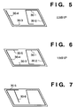
- Figs. 2 to 6 are views when the length of the antenna line 30 is increased.
- the reception sensitivity of AM radio waves obtained when only the antenna line 20 is arranged is assumed to be a reference (0 dB), as shown in Fig. 2, the sensitivity rises by 3 dB upon adding the AM line 30-1 (see Fig. 3); the sensitivity further rises by 1.9 dB upon adding the AM lines 30-2 and 30-3 (see Fig. 4); the sensitivity rises by 2.2 dB upon adding the AM line 30-4 (see Fig. 5); and the sensitivity rises by 1.5 dB upon adding the AM line 30-5 (see Fig. 6).
- the antenna lines with the arrangement shown in Fig. 1 can raise the reception sensitivity by a total of 8.6 dB as compared to the antenna system shown in Fig. 2.
- an additional line is added for the purpose of further improving the reception sensitivity of AM radio waves. More specifically, if the additional line 30-5 is further extended, it would approach the antenna line 20 and adversely influence the sensitivity of the FM antenna. In order to prevent this, an AM additional line 30-6 is added to extend parallel to the antenna line 20, as shown in Fig. 7. An additional line of the antenna line 30 should originally extend along the edge of the glass. Because the additional line extends to be separated away from the edge of the glass surface, as shown in Fig. 7, addition of additional antenna line gives less reception sensitivity. In this connection, in the example shown in Fig. 7, when the additional line 30-6 is added, the sensitivity rises by 0.6 dB. In order to expect further improvement of AM reception sensitivity, another additional line can be added parallel to the additional line 30-6.
- the AM additional antenna line 30-6 can be arranged at a position where it does not disturb the view field of a driver/passenger, and is located at an intermediate position (need not be the center) between the antenna additional line 30-4 and the antenna line 20-1.
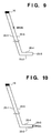
- Fig. 8 shows a countermeasure against breaking of the line.
- additional lines 20-3, 20-4, and 20-5 are further provided to the FM antenna line 20-2, and the terminal end of the additional line 20-5 is connected to the feeding point 16.
- the FM antenna line 20-1 and the additional lines 20-2, 20-3, 20-4, and 20-5 form a single loop. In other words, the FM antenna line is doubled. Even when the antenna line breaks at any position, the broken FM antennas serve as two monopole type antennas, and the FM reception characteristics can be maintained.
- Fig. 9 shows a case wherein the additional line 20-5 is broken (i.e., the antenna line is broken halfway), and Fig. 10 shows a case wherein the additional line 20-3 is broken (i.e., the distal end portion of the antenna line is broken).
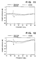
- Solid curves I in Figs. 11 and 12 respectively represent the reception sensitivity characteristics for horizontally and vertically polarized waves when the antenna line is free from breaking.
- Broken curves II in Figs. 11 and 12 respectively represent the reception sensitivity characteristics for horizontally and vertically polarized waves when the antenna line is broken, as shown in Fig. 9.
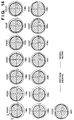
- Solid curves I in Figs. 13 and 14 respectively represent the directivity characteristics for horizontally and vertically polarized waves when the antenna line is free from breaking.
- Broken curves II in Figs. 13 and 14 respectively represent the directivity characteristics for horizontally and vertically polarized waves when the antenna line is broken, as shown in Fig. 9.
- the directivity does not deteriorate even when the antenna line breaks.
- Solid curves I in Figs. 15 and 16 respectively represent the reception sensitivity characteristics for horizontally and vertically polarized waves when the antenna line is free from breaking.
- Broken curves II in Figs. 15 and 16 respectively represent the reception sensitivity characteristics for horizontally and vertically polarized waves when the distal end portion of the antenna line is broken, as shown in Fig. 10. As can be seen from Figs. 15 and 16, the sensitivity does not deteriorate to a degree that causes an audible difference.
- Solid curves I in Figs. 17 and 18 respectively represent the directivity characteristics for horizontally and vertically polarized waves when the antenna line is free from breaking.
- Broken curves II in Figs. 17 and 18 respectively represent the directivity characteristics for horizontally and vertically polarized waves when the antenna line is broken, as shown in Fig. 10. As can be seen from Figs. 17 and 18, the directivity does not deteriorate even when the antenna line breaks.
- the AM reception sensitivity is further improved.
- the second embodiment is characterized in that AM antenna lines extend across two glass surfaces.
- Fig. 19 is a view for explaining the arrangement of an antenna system according to the second embodiment.
- a glass 10L represents a left side window glass as in the first embodiment
- a glass 10R represents a right side window glass which opposes the left side window glass 10L.
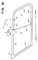
- the glasses 10L and 10R have a rectangular shape in Fig. 19, but actually have a substantially parallelogram shape as in the first embodiment, as shown in Fig. 20 or may have an arbitrary shape.
- an AM antenna line 31 including AM reception additional antenna lines 31-1, 31-2, 31-3, 31-4, and 31-5 extends.
- An AM antenna line 30 arranged on the left side window glass 10L and the AM antenna line 31 arranged on the right side window glass 10R are connected via a connection line 14.
- the connection line 14 is connected to the AM antenna line 30 arranged on the left side window glass 10L at a connection point 15L, and is connected to the AM antenna line 31 arranged on the right side window glass 10R at a connection point 15R.
- an antenna line 20 is mainly used for FM reception, and for the AM frequency band, the antenna line 20 and the antenna lines 30 and 31 serve as an antenna conductor.
- antenna lines 20-1 and 20-2 constitute an FM antenna
- three sets of antenna lines i.e., the antenna lines 20-1 and 20-2, antenna lines 30-1, 30-2, 30-3, 30-4, and 30-5
- the antenna lines 31-1, 31-2, 31-3, 31-4, and 31-5 constitute an AM antenna.
- cables 11L and 11R are cable harnesses which are arranged below the glasses 10L and 10R and are normally concealed by the vehicle body.
- Fig. 20 shows the layout of the antenna lines 20 and 30 extending on the left side window glass 10L shown in Fig. 19.
- Fig. 21 shows the layout of the AM antenna line 31 extending on the right side window glass 10R.
- extension of AM antenna lines must not have any adverse influence on the reception of FM radio waves.
- the impedance of the antenna line is inevitably low.
- a line, between the feeding point 16 and the connection point 15L, of the AM antenna line 30-1 serves as a stub for attaining impedance matching between the antenna line and a feeder line 13.
- a stub is normally used for attaining impedance matching between an antenna line and a feeder line. Since the distribution constant of the stub portion changes the impedance of the antenna line, the length of the stub portion is appropriately determined to attain impedance matching between the antenna line and the feeder line and to eliminate generation of reflected waves.
- connection line for connecting the antenna lines on the right and left glasses serves as a normal stub by using a normal AV line in place of a coaxial cable and by appropriately setting the position of the connection point 15L, and the AM antenna line 30 on the left glass 10L and the AM antenna line 31 on the right glass 10R are set to have a higher impedance when viewed from the antenna line 20.
- the AM antenna lines 30 and 31 stand as if they did not exist from the viewpoint of the FM antenna line 20, and their influence on the antenna line 20 is negligible.
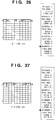
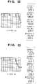
- Figs. 22 to 33 show the impedance characteristics (VSWR) for the respective FM frequencies obtained when the position of the connection point 15L of the connection line 14 to be connected to the antenna line 31 on the right glass is variously changed on the left glass surface.
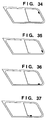
- Figs. 34 to 44 respectively show the positions of the connection point 15L in the VSWR graphs shown in Figs. 23 to 33.
- Fig. 45 is a VSWR graph obtained when no right side glass is present. As can be seen from Figs. 22 to 33, high VSWR characteristics can be obtained over a broad frequency range when the connection point 15L is separated from the feeding point 16 by an appropriate distance and is set at the edge of the glass surface. Furthermore, as can be seen from Fig. 45, when the AM antenna lines are present on the right and left glasses, higher VSWR characteristics can be obtained as compared to a case wherein no AM antenna line is present on the right glass.
- the antenna line 31 even when the AM antenna line 31 is present on the right glass 10R, the antenna line 31 has a higher impedance than that of the antenna line 20, and its presence has no influence on the FM reception characteristics.
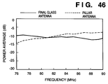
- Fig. 46 shows the reception sensitivity characteristics (solid curve) obtained when horizontally polarized FM radio waves are received by the antenna system having an open stub structure (the structure having the AM line 30) of the second embodiment, and the reception sensitivity characteristics (broken curve) obtained when horizontally polarized FM radio waves are received by an antenna system (not shown) arranged on a pillar.
- Fig. 47 shows the directivity characteristics (solid curve) obtained when horizontally polarized FM radio waves are received by the antenna system of the second embodiment, and the directivity characteristics (broken curve) obtained when horizontally polarized FM radio waves are received by the pillar antenna system.
- Fig. 46 shows the reception sensitivity characteristics (solid curve) obtained when horizontally polarized FM radio waves are received by the antenna system having an open stub structure (the structure having the AM line 30) of the second embodiment, and the reception sensitivity characteristics (broken curve) obtained when horizontally polarized FM radio waves are received by an antenna system (not shown) arranged on a pillar.
- Fig. 47 shows
- FIG. 48 shows the reception sensitivity characteristics (solid curve) obtained when vertically polarized FM radio waves are received by the antenna system of the second embodiment, and the reception sensitivity characteristics (broken curve) obtained when vertically polarized FM radio waves are received by the pillar antenna system.
- Figs. 46 to 48 reveal that the FM reception performance of the antenna system having a stub structure of the second embodiment is equivalent to that of the pillar antenna system.
- Fig. 49 shows the reception sensitivity characteristics (solid curve) obtained when horizontally polarized FM radio waves (76 MHz to 90 MHz) are received by the antenna system having an open stub structure (the structure having the AM additional line 30) of the second embodiment, and the reception sensitivity characteristics (broken curve) obtained when the horizontally polarized FM radio waves are received by an antenna system without any stub structure (not shown; an antenna system constituted by only the antenna line 20 without any AM antenna line 30 in Fig. 20).
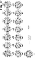
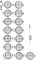
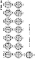
- Fig. 50 shows charts for comparing the directivity characteristics for the FM radio waves between the antenna system (solid curve) of the second embodiment and an antenna system (broken curve) without any stub structure.
- FIG. 51 shows the reception sensitivity characteristics (solid curve) obtained when horizontally polarized FM radio waves (88 MHz to 108 MHz) are received by the antenna system having a stub structure of the second embodiment, and the reception sensitivity characteristics (broken curve) obtained when the horizontally polarized FM radio waves are received by the antenna system without any stub structure.
- Fig. 52 shows charts for comparing the directivity characteristics for the FM radio waves between the antenna system (solid curve) of the second embodiment and an antenna system (broken curve) without any stub structure.
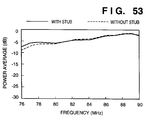
- FIG. 53 shows the reception sensitivity characteristics (solid curve) obtained when vertically polarized FM radio waves (76 MHz to 90 MHz) are received by the antenna system having a stub structure of the second embodiment, and the reception sensitivity characteristics (broken curve) obtained when the vertically polarized FM radio waves are received by the antenna system without any stub structure.
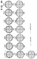
- Fig. 54 shows charts for comparing the directivity characteristics for the FM radio waves between the antenna system (solid curve) of the second embodiment and an antenna system (broken curve) without any stub structure.
- Figs. 49 to 54 indicate that the AM antenna line for the stub structure has no influence on the reception performance (reception sensitivity and directivity) of FM radio waves.
- Fig. 55 shows the reception sensitivity characteristics (solid curve) obtained when horizontally polarized FM radio waves (76 MHz to 90 MHz) are received by the antenna system of the second embodiment, and the reception sensitivity characteristics (broken curve) obtained when the horizontally polarized FM radio waves are received by the antenna system of the first embodiment.
- Fig. 56 shows the directivity characteristics (solid curve) obtained when the FM radio waves are received by the antenna system of the second embodiment, and the directivity characteristics (broken curve) obtained when the FM radio waves are received by the antenna system of the first embodiment.
- Figs. 54 and 55 reveal that the open stub structure of the second embodiment can provide FM reception performance free from the influence of the AM antenna line since it allows to ignore the influence of the antenna line 31 on the right glass.
- the antenna line arranged on the right glass may, of course, be the antenna line as shown in Fig. 21, or may be replaced by, e.g., a monopole type antenna line or a loop antenna line.
- a reception signal of FM radio waves received by the AM antenna line 31 is not supplied to the feeding point 16 via the connection line 14, and for example, a coil for cutting an FM signal, which is required in a conventional system, can be omitted.
- Tables below compare the reception sensitivity characteristics for AM radio waves of the antenna system of the second embodiment (also, the antenna system of the first embodiment) with those of a conventional pillar antenna. Especially, Tables 1 and 2 show examples using AV lines as the connection line 14, and Table 3 summarizes the AM reception sensitivity obtained when the type of the connection line is variously changed.
- Table 1 summarizes data for the antenna systems of the first and second embodiments constituted using a 75-W 1.5C cable between the antenna and tuner.
- Table 1 Using 1.5C Cable 666 kHz 1,035 kHz 1,458 kHz Pillar Antenna 15.0 dB 62.6 dB 61.1 dB First Embodiment 5.8 dB 52.5 dB 51.6 dB Second Embodiment 9.2 dB 56.6 dB 55.7 dB
- Table 2 Using Low-capacitance Cable 666 kHz 1,035 kHz 1,458 kHz First Embodiment 9.2 dB 56.2 dB 55.0 dB Second Embodiment 9.2 dB 56.6 dB 58.5 dB
- the AM antenna line 31 on the right glass surface which is connected to the antenna line 30 on the left glass surface via the AV line 14 serves to correct the AM sensitivity.
- the sensitivity improves by about 4 dB on average
- the sensitivity improves by about 3 dB on average.
- the AM antenna line 31 on the right glass greatly contributes to improvement of the AM sensitivity.
- the sensitivity improves by about 2 dB on average as compared to that obtained when the coaxial cable is used.
- the parasitic capacitance in the cable acts as a reactive capacitance, resulting in a sensitivity loss.
- the antenna line When the antenna line is attached to the side window glass, the following problem is posed: many signal lines run in the side surface of the vehicle body, and may serve as a noise source if the cable of the signal lines is close to the antenna line on the glass surface.
- the antenna system of the second embodiment distributes the AM reception sensitivity by extending the AM reception antenna lines on the right and left side window glasses.
- This layout lowers the reception sensitivity of each of the antenna lines 30 and 31 on the two glass surfaces. Therefore, the AM reception antenna line with low sensitivity can provide the merit of low reception sensitivity to noise.
- the distance between the glass edge and the antenna line 30-3 on the left glass 10L is 30 mm, while the distance between the glass edge and the lowermost portion of each of the antenna lines 31-3, 31-4, and 31-5 on the right glass 10R is 80 mm. More specifically, the distance between the antenna line on the right glass 10R and the noise source is set to be larger than that from the noise source on the left glass. In other words, the reception sensitivity to noise on the right glass relatively lowers. Furthermore, the antenna line 30-3 is arranged on the left glass to extend horizontally rearward, while no AM antenna line extending in the horizontal direction is arranged on the lower portion of the right glass. This layout also contributes to lower the noise reception sensitivity on the right glass.
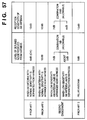
- Fig. 57 is a table showing the comparison results between the prior arts (1 to 3) and the second embodiment which adopts the distributed layout of the AM antenna lines 30 and 31 and the method of separating the antenna line on the right glass from the noise source.
- the low-sensitivity left antenna line 30 (-5 dB) is arranged near the harness (separated by 30 mm from the glass edge, as shown in Fig. 20), and the low-sensitivity right antenna line 31 (-8 dB) is arranged to be largely separated from the harness (by 80 mm from the glass edge, as shown in Fig. 21).
- the AM reception sensitivity of the left antenna line 30 is 7 dB and the reception sensitivity of the right antenna line 31 is 4 dB, a reception sensitivity of a total of 11 dB is obtained in the entire system, and no practical problem is posed.
- the level of detuned noise received by the left antenna line 30 is 7 dB and the level of detuned noise received by the right antenna line 31 is 0 dB, i.e., a total of 7 dB, this value falls within the allowable range.
- the second embodiment can obtain the following effects:
- a vehicle to which the present invention is to be applied is not limited to vehicles such as a van, wagon, or the like.
- the present invention can be applied to any other vehicles as long as they have window glasses.
- the position of the glass to which the present invention is to be applied is not limited to the side window glass near a rear passenger seat.
- the present invention can be applied to any other glass surfaces of a vehicle according to its principle.
- the position of the glass antenna of the first embodiment is not limited to the glass near the rear passenger seat, but may be applied to the glass surfaces near all the seats or to the rear glass surface in some cases.
- the number of glasses to which the glass antenna of the present invention is applied can be two or more. Combinations of two or more glasses are not particularly limited.
- the antenna system may be arranged on one right (or left) glass near a front passenger seat and one left (or right) glass near a rear passenger seat. That is, in the second embodiment, the position of the additional antenna line 31 for the low-frequency band (AM) is not particularly limited in principle as long as it is arranged on a glass different from that of the primary antenna line 30 for this frequency band.
- AM low-frequency band
- the present invention is not limited to the AM and FM receptions.
- the present invention can be applied to reception of radio waves in two ranges, e.g., high and middle (or low) frequency bands.
- the series connection of antenna lines via the AV line according to the second embodiment can be applied to antenna lines extending on three or more glasses in principle.
Landscapes
- Details Of Aerials (AREA)
Applications Claiming Priority (6)
| Application Number | Priority Date | Filing Date | Title |
|---|---|---|---|
| JP6266895 | 1995-03-22 | ||
| JP6266795 | 1995-03-22 | ||
| JP62667/95 | 1995-03-22 | ||
| JP62668/95 | 1995-03-22 | ||
| JP06266795A JP3541979B2 (ja) | 1995-03-22 | 1995-03-22 | 車両用ガラスアンテナ及びその設計方法 |
| JP06266895A JP3543308B2 (ja) | 1995-03-22 | 1995-03-22 | 車両用ガラスアンテナ |
Publications (3)
| Publication Number | Publication Date |
|---|---|
| EP0734091A2 true EP0734091A2 (de) | 1996-09-25 |
| EP0734091A3 EP0734091A3 (de) | 1997-05-14 |
| EP0734091B1 EP0734091B1 (de) | 2001-06-06 |
Family
ID=26403716
Family Applications (1)
| Application Number | Title | Priority Date | Filing Date |
|---|---|---|---|
| EP96103950A Expired - Lifetime EP0734091B1 (de) | 1995-03-22 | 1996-03-13 | Scheibenantenne für Kraftfahrzeuge und Verfahren zum Entwerfen einer derartigen Antenne |
Country Status (5)
| Country | Link |
|---|---|
| US (1) | US5793333A (de) |
| EP (1) | EP0734091B1 (de) |
| KR (1) | KR100339748B1 (de) |
| CN (1) | CN1138221A (de) |
| DE (1) | DE69613167T2 (de) |
Cited By (1)
| Publication number | Priority date | Publication date | Assignee | Title |
|---|---|---|---|---|
| EP0851527A3 (de) * | 1996-12-20 | 1998-11-04 | Central Glass Company, Limited | Fahrzeugseitenfensterantenne für Rundfunkempfang |
Families Citing this family (9)
| Publication number | Priority date | Publication date | Assignee | Title |
|---|---|---|---|---|
| EP0954054A1 (de) * | 1998-04-30 | 1999-11-03 | Kabushiki Kaisha Yokowo | Gefaltete Antenne |
| US6215450B1 (en) * | 1998-06-03 | 2001-04-10 | Nippon Sheet Glass Co., Ltd. | Glass window antenna system for motor vehicles |
| JP3783689B2 (ja) * | 2003-02-28 | 2006-06-07 | ソニー株式会社 | アンテナ装置 |
| CN100589277C (zh) * | 2003-03-19 | 2010-02-10 | 中央硝子株式会社 | 车用天线 |
| EP1605543A4 (de) * | 2003-03-19 | 2009-06-17 | Central Glass Co Ltd | Antenne für ein fahrzeug |
| DE10331213B4 (de) * | 2003-07-10 | 2016-02-25 | Blaupunkt Antenna Systems Gmbh & Co. Kg | Scheibenantenne für den LMK- und diversitären FM-Empfang mobiler Kraftfahrzeuge |
| US6943741B2 (en) * | 2004-01-16 | 2005-09-13 | Delphi Technologies, Inc. | AM/FM on-glass wire grid antenna |
| JP5640516B2 (ja) | 2010-07-15 | 2014-12-17 | セントラル硝子株式会社 | 車両用ガラスアンテナ |
| JP7700509B2 (ja) * | 2021-05-17 | 2025-07-01 | Agc株式会社 | 車両用アンテナ装置 |
Family Cites Families (13)
| Publication number | Priority date | Publication date | Assignee | Title |
|---|---|---|---|---|
| JPS5148907Y1 (de) * | 1970-03-04 | 1976-11-25 | ||
| DE2160458C3 (de) * | 1970-12-08 | 1980-04-10 | Saint-Gobain Industries, Neuilly- Sur-Seine (Frankreich) | Auf oder in einer Sichtscheibe angeordnete Antenne, insbesondere für Kraftfahrzeuge |
| US3971030A (en) * | 1972-01-14 | 1976-07-20 | Saint-Gobain Industries | Antenna window |
| IT1041016B (it) * | 1975-07-24 | 1980-01-10 | Siv Soc Italiana Vetro | Antenna radioricevente multiband supportata su lastra per finestratura |
| GB1554911A (en) * | 1976-07-29 | 1979-10-31 | Siv Soc Italiana Vetro | Spa multiband antenna for window panes |
| IT1138605B (it) * | 1981-09-15 | 1986-09-17 | Siv Soc Italiana Vetro | Antenna multibanda,particolarmente adatta ad una vetratura di autoveicolo |
| JPS61265904A (ja) * | 1985-05-20 | 1986-11-25 | Toyota Motor Corp | 自動車用窓ガラスアンテナ |
| JPH032975Y2 (de) * | 1985-05-30 | 1991-01-25 | ||
| CA1258705A (en) * | 1985-06-21 | 1989-08-22 | Hiroshi Kondo | Automobile antenna system |
| GB2216341B (en) * | 1988-02-25 | 1992-01-22 | Central Glass Co Ltd | Vehicle window glass antenna suited to reception of fm radio and tv broadcasting |
| JPH01292902A (ja) * | 1988-05-20 | 1989-11-27 | Central Glass Co Ltd | 車両用ガラスアンテナ |
| JPH0758850B2 (ja) * | 1989-07-24 | 1995-06-21 | セントラル硝子株式会社 | 車両用のガラスアンテナ |
| JP3206912B2 (ja) * | 1990-07-16 | 2001-09-10 | 日本板硝子株式会社 | 自動車用窓ガラスアンテナ |
-
1996
- 1996-03-13 EP EP96103950A patent/EP0734091B1/de not_active Expired - Lifetime
- 1996-03-13 DE DE69613167T patent/DE69613167T2/de not_active Expired - Fee Related
- 1996-03-19 US US08/617,593 patent/US5793333A/en not_active Expired - Lifetime
- 1996-03-21 CN CN96103152A patent/CN1138221A/zh active Pending
- 1996-03-22 KR KR1019960007815A patent/KR100339748B1/ko not_active Expired - Fee Related
Cited By (2)
| Publication number | Priority date | Publication date | Assignee | Title |
|---|---|---|---|---|
| EP0851527A3 (de) * | 1996-12-20 | 1998-11-04 | Central Glass Company, Limited | Fahrzeugseitenfensterantenne für Rundfunkempfang |
| US5905470A (en) * | 1996-12-20 | 1999-05-18 | Central Glass Company, Limited | Vehicle side window glass antenna for radio broadcast waves |
Also Published As
| Publication number | Publication date |
|---|---|
| KR960036198A (ko) | 1996-10-28 |
| CN1138221A (zh) | 1996-12-18 |
| DE69613167T2 (de) | 2001-10-11 |
| EP0734091A3 (de) | 1997-05-14 |
| DE69613167D1 (de) | 2001-07-12 |
| EP0734091B1 (de) | 2001-06-06 |
| US5793333A (en) | 1998-08-11 |
| KR100339748B1 (ko) | 2002-10-09 |
Similar Documents
| Publication | Publication Date | Title |
|---|---|---|
| US5442368A (en) | Automobile loop antenna | |
| US7456796B2 (en) | Glass antenna for vehicle | |
| US5119106A (en) | Glass window antenna for a motor vehicle | |
| US5231410A (en) | Window glass antenna for a motor vehicle | |
| JP3974087B2 (ja) | 車両用ガラスアンテナ | |
| US5793333A (en) | Glass antenna for vehicles, and designing method of the same | |
| US5663737A (en) | Window glass antenna for automobile telephone | |
| EP0367225B1 (de) | Scheibenantenne für Kraftfahrzeuge | |
| EP0766337B1 (de) | Scheibenantenne für Kraftfahrzeuge | |
| US6031500A (en) | Broadband FM vehicle rear window antenna not requiring a boost amplifier | |
| US5883599A (en) | Antenna system for a motor vehicle | |
| JP3613097B2 (ja) | 車両用ガラスアンテナ | |
| JP3206912B2 (ja) | 自動車用窓ガラスアンテナ | |
| JP2002299932A (ja) | 車両用のガラスアンテナ | |
| JP4225373B2 (ja) | 車両用のガラスアンテナ | |
| JP3543308B2 (ja) | 車両用ガラスアンテナ | |
| US4329691A (en) | AM-FM Broadband vehicle windshield mounted radio antenna | |
| JP3541979B2 (ja) | 車両用ガラスアンテナ及びその設計方法 | |
| JP3201710B2 (ja) | 自動車用窓ガラスアンテナ | |
| JPH08222930A (ja) | ガラスアンテナ | |
| JP2005130414A (ja) | 車両用のガラスアンテナ | |
| GB2316538A (en) | Vehicle windscreen antenna and heater element arrangement | |
| JP3786756B2 (ja) | 自動車用のガラスアンテナ | |
| KR100290319B1 (ko) | 리어글라스안테나 | |
| JPH01106502A (ja) | 自動車用ガラスアンテナ |
Legal Events
| Date | Code | Title | Description |
|---|---|---|---|
| PUAI | Public reference made under article 153(3) epc to a published international application that has entered the european phase |
Free format text: ORIGINAL CODE: 0009012 |
|
| AK | Designated contracting states |
Kind code of ref document: A2 Designated state(s): DE FR GB |
|
| PUAL | Search report despatched |
Free format text: ORIGINAL CODE: 0009013 |
|
| AK | Designated contracting states |
Kind code of ref document: A3 Designated state(s): DE FR GB |
|
| RHK1 | Main classification (correction) |
Ipc: H01Q 1/12 |
|
| 17P | Request for examination filed |
Effective date: 19971114 |
|
| 17Q | First examination report despatched |
Effective date: 19980414 |
|
| GRAG | Despatch of communication of intention to grant |
Free format text: ORIGINAL CODE: EPIDOS AGRA |
|
| GRAG | Despatch of communication of intention to grant |
Free format text: ORIGINAL CODE: EPIDOS AGRA |
|
| GRAH | Despatch of communication of intention to grant a patent |
Free format text: ORIGINAL CODE: EPIDOS IGRA |
|
| GRAH | Despatch of communication of intention to grant a patent |
Free format text: ORIGINAL CODE: EPIDOS IGRA |
|
| GRAA | (expected) grant |
Free format text: ORIGINAL CODE: 0009210 |
|
| AK | Designated contracting states |
Kind code of ref document: B1 Designated state(s): DE FR GB |
|
| REF | Corresponds to: |
Ref document number: 69613167 Country of ref document: DE Date of ref document: 20010712 |
|
| ET | Fr: translation filed | ||
| REG | Reference to a national code |
Ref country code: GB Ref legal event code: IF02 |
|
| PG25 | Lapsed in a contracting state [announced via postgrant information from national office to epo] |
Ref country code: GB Free format text: LAPSE BECAUSE OF NON-PAYMENT OF DUE FEES Effective date: 20020313 |
|
| PLBE | No opposition filed within time limit |
Free format text: ORIGINAL CODE: 0009261 |
|
| STAA | Information on the status of an ep patent application or granted ep patent |
Free format text: STATUS: NO OPPOSITION FILED WITHIN TIME LIMIT |
|
| 26N | No opposition filed | ||
| GBPC | Gb: european patent ceased through non-payment of renewal fee |
Effective date: 20020313 |
|
| PG25 | Lapsed in a contracting state [announced via postgrant information from national office to epo] |
Ref country code: FR Free format text: LAPSE BECAUSE OF NON-PAYMENT OF DUE FEES Effective date: 20021129 |
|
| REG | Reference to a national code |
Ref country code: FR Ref legal event code: ST |
|
| PGFP | Annual fee paid to national office [announced via postgrant information from national office to epo] |
Ref country code: DE Payment date: 20030320 Year of fee payment: 8 |
|
| PG25 | Lapsed in a contracting state [announced via postgrant information from national office to epo] |
Ref country code: DE Free format text: LAPSE BECAUSE OF NON-PAYMENT OF DUE FEES Effective date: 20041001 |