EP0740952B1 - Mikroporöser polyolefinverbundfilm und verfahren zur dessen herstellung - Google Patents
Mikroporöser polyolefinverbundfilm und verfahren zur dessen herstellung Download PDFInfo
- Publication number
- EP0740952B1 EP0740952B1 EP95906482A EP95906482A EP0740952B1 EP 0740952 B1 EP0740952 B1 EP 0740952B1 EP 95906482 A EP95906482 A EP 95906482A EP 95906482 A EP95906482 A EP 95906482A EP 0740952 B1 EP0740952 B1 EP 0740952B1
- Authority
- EP
- European Patent Office
- Prior art keywords
- membrane
- layer
- micropores
- composite
- composite microporous
- Prior art date
- Legal status (The legal status is an assumption and is not a legal conclusion. Google has not performed a legal analysis and makes no representation as to the accuracy of the status listed.)
- Expired - Lifetime
Links
Images


Classifications
-
- B—PERFORMING OPERATIONS; TRANSPORTING
- B01—PHYSICAL OR CHEMICAL PROCESSES OR APPARATUS IN GENERAL
- B01D—SEPARATION
- B01D67/00—Processes specially adapted for manufacturing semi-permeable membranes for separation processes or apparatus
- B01D67/0081—After-treatment of organic or inorganic membranes
- B01D67/0088—Physical treatment with compounds, e.g. swelling, coating or impregnation
-
- B—PERFORMING OPERATIONS; TRANSPORTING
- B01—PHYSICAL OR CHEMICAL PROCESSES OR APPARATUS IN GENERAL
- B01D—SEPARATION
- B01D69/00—Semi-permeable membranes for separation processes or apparatus characterised by their form, structure or properties; Manufacturing processes specially adapted therefor
- B01D69/02—Semi-permeable membranes for separation processes or apparatus characterised by their form, structure or properties; Manufacturing processes specially adapted therefor characterised by their properties
-
- B—PERFORMING OPERATIONS; TRANSPORTING
- B01—PHYSICAL OR CHEMICAL PROCESSES OR APPARATUS IN GENERAL
- B01D—SEPARATION
- B01D69/00—Semi-permeable membranes for separation processes or apparatus characterised by their form, structure or properties; Manufacturing processes specially adapted therefor
- B01D69/08—Hollow fibre membranes
-
- B—PERFORMING OPERATIONS; TRANSPORTING
- B01—PHYSICAL OR CHEMICAL PROCESSES OR APPARATUS IN GENERAL
- B01D—SEPARATION
- B01D69/00—Semi-permeable membranes for separation processes or apparatus characterised by their form, structure or properties; Manufacturing processes specially adapted therefor
- B01D69/12—Composite membranes; Ultra-thin membranes
-
- B—PERFORMING OPERATIONS; TRANSPORTING
- B01—PHYSICAL OR CHEMICAL PROCESSES OR APPARATUS IN GENERAL
- B01D—SEPARATION
- B01D71/00—Semi-permeable membranes for separation processes or apparatus characterised by the material; Manufacturing processes specially adapted therefor
- B01D71/06—Organic material
- B01D71/26—Polyalkenes
- B01D71/261—Polyethylene
-
- B—PERFORMING OPERATIONS; TRANSPORTING
- B29—WORKING OF PLASTICS; WORKING OF SUBSTANCES IN A PLASTIC STATE IN GENERAL
- B29C—SHAPING OR JOINING OF PLASTICS; SHAPING OF MATERIAL IN A PLASTIC STATE, NOT OTHERWISE PROVIDED FOR; AFTER-TREATMENT OF THE SHAPED PRODUCTS, e.g. REPAIRING
- B29C55/00—Shaping by stretching, e.g. drawing through a die; Apparatus therefor
- B29C55/005—Shaping by stretching, e.g. drawing through a die; Apparatus therefor characterised by the choice of materials
-
- B—PERFORMING OPERATIONS; TRANSPORTING
- B29—WORKING OF PLASTICS; WORKING OF SUBSTANCES IN A PLASTIC STATE IN GENERAL
- B29K—INDEXING SCHEME ASSOCIATED WITH SUBCLASSES B29B, B29C OR B29D, RELATING TO MOULDING MATERIALS OR TO MATERIALS FOR MOULDS, REINFORCEMENTS, FILLERS OR PREFORMED PARTS, e.g. INSERTS
- B29K2023/00—Use of polyalkenes or derivatives thereof as moulding material
-
- B—PERFORMING OPERATIONS; TRANSPORTING
- B29—WORKING OF PLASTICS; WORKING OF SUBSTANCES IN A PLASTIC STATE IN GENERAL
- B29K—INDEXING SCHEME ASSOCIATED WITH SUBCLASSES B29B, B29C OR B29D, RELATING TO MOULDING MATERIALS OR TO MATERIALS FOR MOULDS, REINFORCEMENTS, FILLERS OR PREFORMED PARTS, e.g. INSERTS
- B29K2023/00—Use of polyalkenes or derivatives thereof as moulding material
- B29K2023/04—Polymers of ethylene
- B29K2023/08—Copolymers of ethylene
- B29K2023/086—EVOH, i.e. ethylene vinyl alcohol copolymer
-
- B—PERFORMING OPERATIONS; TRANSPORTING
- B29—WORKING OF PLASTICS; WORKING OF SUBSTANCES IN A PLASTIC STATE IN GENERAL
- B29K—INDEXING SCHEME ASSOCIATED WITH SUBCLASSES B29B, B29C OR B29D, RELATING TO MOULDING MATERIALS OR TO MATERIALS FOR MOULDS, REINFORCEMENTS, FILLERS OR PREFORMED PARTS, e.g. INSERTS
- B29K2105/00—Condition, form or state of moulded material or of the material to be shaped
- B29K2105/04—Condition, form or state of moulded material or of the material to be shaped cellular or porous
-
- Y—GENERAL TAGGING OF NEW TECHNOLOGICAL DEVELOPMENTS; GENERAL TAGGING OF CROSS-SECTIONAL TECHNOLOGIES SPANNING OVER SEVERAL SECTIONS OF THE IPC; TECHNICAL SUBJECTS COVERED BY FORMER USPC CROSS-REFERENCE ART COLLECTIONS [XRACs] AND DIGESTS
- Y02—TECHNOLOGIES OR APPLICATIONS FOR MITIGATION OR ADAPTATION AGAINST CLIMATE CHANGE
- Y02E—REDUCTION OF GREENHOUSE GAS [GHG] EMISSIONS, RELATED TO ENERGY GENERATION, TRANSMISSION OR DISTRIBUTION
- Y02E60/00—Enabling technologies; Technologies with a potential or indirect contribution to GHG emissions mitigation
- Y02E60/10—Energy storage using batteries
-
- Y—GENERAL TAGGING OF NEW TECHNOLOGICAL DEVELOPMENTS; GENERAL TAGGING OF CROSS-SECTIONAL TECHNOLOGIES SPANNING OVER SEVERAL SECTIONS OF THE IPC; TECHNICAL SUBJECTS COVERED BY FORMER USPC CROSS-REFERENCE ART COLLECTIONS [XRACs] AND DIGESTS
- Y10—TECHNICAL SUBJECTS COVERED BY FORMER USPC
- Y10S—TECHNICAL SUBJECTS COVERED BY FORMER USPC CROSS-REFERENCE ART COLLECTIONS [XRACs] AND DIGESTS
- Y10S428/00—Stock material or miscellaneous articles
- Y10S428/902—High modulus filament or fiber
-
- Y—GENERAL TAGGING OF NEW TECHNOLOGICAL DEVELOPMENTS; GENERAL TAGGING OF CROSS-SECTIONAL TECHNOLOGIES SPANNING OVER SEVERAL SECTIONS OF THE IPC; TECHNICAL SUBJECTS COVERED BY FORMER USPC CROSS-REFERENCE ART COLLECTIONS [XRACs] AND DIGESTS
- Y10—TECHNICAL SUBJECTS COVERED BY FORMER USPC
- Y10S—TECHNICAL SUBJECTS COVERED BY FORMER USPC CROSS-REFERENCE ART COLLECTIONS [XRACs] AND DIGESTS
- Y10S428/00—Stock material or miscellaneous articles
- Y10S428/91—Product with molecular orientation
-
- Y—GENERAL TAGGING OF NEW TECHNOLOGICAL DEVELOPMENTS; GENERAL TAGGING OF CROSS-SECTIONAL TECHNOLOGIES SPANNING OVER SEVERAL SECTIONS OF THE IPC; TECHNICAL SUBJECTS COVERED BY FORMER USPC CROSS-REFERENCE ART COLLECTIONS [XRACs] AND DIGESTS
- Y10—TECHNICAL SUBJECTS COVERED BY FORMER USPC
- Y10T—TECHNICAL SUBJECTS COVERED BY FORMER US CLASSIFICATION
- Y10T428/00—Stock material or miscellaneous articles
- Y10T428/249921—Web or sheet containing structurally defined element or component
- Y10T428/249953—Composite having voids in a component [e.g., porous, cellular, etc.]
- Y10T428/249975—Void shape specified [e.g., crushed, flat, round, etc.]
-
- Y—GENERAL TAGGING OF NEW TECHNOLOGICAL DEVELOPMENTS; GENERAL TAGGING OF CROSS-SECTIONAL TECHNOLOGIES SPANNING OVER SEVERAL SECTIONS OF THE IPC; TECHNICAL SUBJECTS COVERED BY FORMER USPC CROSS-REFERENCE ART COLLECTIONS [XRACs] AND DIGESTS
- Y10—TECHNICAL SUBJECTS COVERED BY FORMER USPC
- Y10T—TECHNICAL SUBJECTS COVERED BY FORMER US CLASSIFICATION
- Y10T428/00—Stock material or miscellaneous articles
- Y10T428/249921—Web or sheet containing structurally defined element or component
- Y10T428/249953—Composite having voids in a component [e.g., porous, cellular, etc.]
- Y10T428/249978—Voids specified as micro
- Y10T428/24998—Composite has more than two layers
-
- Y—GENERAL TAGGING OF NEW TECHNOLOGICAL DEVELOPMENTS; GENERAL TAGGING OF CROSS-SECTIONAL TECHNOLOGIES SPANNING OVER SEVERAL SECTIONS OF THE IPC; TECHNICAL SUBJECTS COVERED BY FORMER USPC CROSS-REFERENCE ART COLLECTIONS [XRACs] AND DIGESTS
- Y10—TECHNICAL SUBJECTS COVERED BY FORMER USPC
- Y10T—TECHNICAL SUBJECTS COVERED BY FORMER US CLASSIFICATION
- Y10T428/00—Stock material or miscellaneous articles
- Y10T428/249921—Web or sheet containing structurally defined element or component
- Y10T428/249953—Composite having voids in a component [e.g., porous, cellular, etc.]
- Y10T428/249981—Plural void-containing components
-
- Y—GENERAL TAGGING OF NEW TECHNOLOGICAL DEVELOPMENTS; GENERAL TAGGING OF CROSS-SECTIONAL TECHNOLOGIES SPANNING OVER SEVERAL SECTIONS OF THE IPC; TECHNICAL SUBJECTS COVERED BY FORMER USPC CROSS-REFERENCE ART COLLECTIONS [XRACs] AND DIGESTS
- Y10—TECHNICAL SUBJECTS COVERED BY FORMER USPC
- Y10T—TECHNICAL SUBJECTS COVERED BY FORMER US CLASSIFICATION
- Y10T428/00—Stock material or miscellaneous articles
- Y10T428/249921—Web or sheet containing structurally defined element or component
- Y10T428/249953—Composite having voids in a component [e.g., porous, cellular, etc.]
- Y10T428/249987—With nonvoid component of specified composition
- Y10T428/249991—Synthetic resin or natural rubbers
-
- Y—GENERAL TAGGING OF NEW TECHNOLOGICAL DEVELOPMENTS; GENERAL TAGGING OF CROSS-SECTIONAL TECHNOLOGIES SPANNING OVER SEVERAL SECTIONS OF THE IPC; TECHNICAL SUBJECTS COVERED BY FORMER USPC CROSS-REFERENCE ART COLLECTIONS [XRACs] AND DIGESTS
- Y10—TECHNICAL SUBJECTS COVERED BY FORMER USPC
- Y10T—TECHNICAL SUBJECTS COVERED BY FORMER US CLASSIFICATION
- Y10T428/00—Stock material or miscellaneous articles
- Y10T428/29—Coated or structually defined flake, particle, cell, strand, strand portion, rod, filament, macroscopic fiber or mass thereof
- Y10T428/2913—Rod, strand, filament or fiber
- Y10T428/2933—Coated or with bond, impregnation or core
- Y10T428/2935—Discontinuous or tubular or cellular core
-
- Y—GENERAL TAGGING OF NEW TECHNOLOGICAL DEVELOPMENTS; GENERAL TAGGING OF CROSS-SECTIONAL TECHNOLOGIES SPANNING OVER SEVERAL SECTIONS OF THE IPC; TECHNICAL SUBJECTS COVERED BY FORMER USPC CROSS-REFERENCE ART COLLECTIONS [XRACs] AND DIGESTS
- Y10—TECHNICAL SUBJECTS COVERED BY FORMER USPC
- Y10T—TECHNICAL SUBJECTS COVERED BY FORMER US CLASSIFICATION
- Y10T428/00—Stock material or miscellaneous articles
- Y10T428/29—Coated or structually defined flake, particle, cell, strand, strand portion, rod, filament, macroscopic fiber or mass thereof
- Y10T428/2913—Rod, strand, filament or fiber
- Y10T428/2973—Particular cross section
- Y10T428/2975—Tubular or cellular
Definitions
- This invention relates to a composite microporous polyolefin membrane, which is effectively used in ultra-filtration and precision filtration, and to a method of producing the same.
- this invention relates to a composite microporous polyolefin membrane having a high separation capability and a high film strength, and comprising a micro-porous polyolefin layer, having a function of reinforcing the film strength, being bonded to at least one surface of a microporous polyolefin layer having the function of separation and to a method of producing the same.
- Microporous membranes are used in a wide variety of applications comprising industrial applications such as a treatment of industrial wastes, a treatment of processing water used in industrial applications, a production of ultrapure water and the like, and air purification applications such as air filters, or bag filters.
- Japanese Patent Laid-Open Publication Sho.57-66114 discloses a polyethylene porous hollow fiber membrane having a uniform microporous structure in the thickness direction of the membrane, wherein slit-like micropores comprising microfibrils oriented in the fiber lengthwise direction and knotted portions of stacked lamella oriented in the thickness direction are stacked inside of membrane walls of hollow fiber membrane, and whereby one surface of the membrane is communicating with the other surface of the membrane.
- the membrane is manufactured by a melt forming of polyethylene followed by a further stretching of the formed body.
- a microporous membrane having the above-mentioned specific structure is formed by steps comprising, subjecting polyethylene to an annealing treatment after being formed under a specific spinning condition, forming crystals composed of stacked lamella (hereinafter referred to "stacked lamella") inside of membrane walls of the formed body, then stretching the formed body thereby increasing the distance between these lamella and promoting the growth of fibrils connecting each crystal of stacked lamella.
- the membrane having the above specific structure is characterized by that it has an excellent mechanical strength and is also high in safety because no solvent is used in the manufacturing process.
- the microporous polyolefin membrane thus obtained by the above-mentioned method has a structure wherein stacking structure of micropores is uniform in the thickness direction of the membrane.
- the data disclosed in the experiments show that the mean pore diameter of the membrane is 0.82 ⁇ m (measured by a mercury porosimeter), and the water permeability is 4.2l/m 2 .hr.mmHg. Although the water permeability of the membrane is large, separation characteristic is not sufficient.
- Japanese Patent Publication Hei.3-70539 also discloses a hydrophilic microporous polyethylene membrane, as shown in Fig.4, covered by ethylene-vinyl alcohol copolymer.
- This membrane has a permeability of 1.1 to 20.2l/m 2 .hr.mmHg.
- this membrane has a 3 dimensionally meshed structure wherein overall micropores are uniform. Therefore, membranes having a higher separation capability does not necessarily have a sufficient permeability.
- a membrane having a maximum pore diameter of 0.15 ⁇ m obtained by the Bubble-Point method has a low permeability of 1.1 l/m 2 .hr.mmHg, and in the range of high separation capability, a sufficient permeability can not necessarily be obtained.
- Japanese Patent Publication Sho.62-44046, and Japanese Patent Laid-Open Publication Sho.62-269706 disclose an invention of composite hollow fiber membrane obtained by joining different layers having microporous structures.
- the air permeability of the membranes obtained by these inventions is shown to be 23,000 l/m 2 .hr.0.5kg.cm -2 . This value may be sufficient enough when used as a membrane for gas filtration, but the water permeability of these films are expected to be extremely low, and therefore, these films are not suitable for a water treatment.
- the Japanese application having the publication number 0 1222766 A describes hollow fiber membranes of polyolefin drawn at a temperature of below -60°C to give fibrillated hollow fiber membranes.
- the peripheral wall is constituted with relatively thick rod groups running perpendicular to the lengthwise direction of the hollow fibers and fibril groups running lengthwise and connecting between individual rods.
- US-A-4 859 535 reveals a porous hollow fiber formed of polyolefin comprising a peripheral wall constituted by a plurality of relatively large rods, or strands of polyolefin which run substantially perpendicular to the longitudinal direction of the hollow-fiber and a plurality of fine fibrils which extend in the longitudinal direction of the hollow-fiber between adjacent rods and are connected thereto.
- a composite microporous membrane having a small decrease of membrane permeability of the membrane irrespective to an increase of the membrane thickness can be provided to meet both requirements by providing a composite micorporous membrane wherein a porous membrane being capable of separating particles of desired diameter is joined by a microporous membrane having micropores having larger diameters than the desired diameters by a predetermined ratio.
- the present inventors have developed the present invention through intensive effort of study to obtain a microporous polyolefin membrane having a high separation capability (the diameter of particle that can be separated is no less than 0.050 ⁇ m) and a high flux value (the speed of water permeation is not less than 0.5 l/m 2 .hr.mmHg, preferably not less than 0.8 l/m 2 .hr.mmHg, and more preferably not less than 1 l /m 2 .hr.mmHg).
- the present invention provides a composite microporous polyolefin membrane comprising microporous layer, b-layer, providing a function of reinforcing the mechanical strength of the membrane, the b-layer being bonded to at least one surface of microporous layer, a-layer, providing a separation function, wherein each a-layer and b-layer is composed of a stacked body of micropores comprising microfibril bundles oriented in the direction of stretching and knotted portion of stacked lamella being connected at both ends of the microfibril bundles, and wherein these micropores are forming interconnected channels that communicate between one surface and the other surface of the composite microporous membrane, and wherein the microfibril bundles and the knotted portions of the stacked lamella which compose the micropores of said microporous membrane are coated by 3 to 30% by weight of hydrophilic polymer, and also wherein the mean distance Da between each microfibril bundle in the micropores existing in a-layer and the average
- Fig.1 shows a cross sectional view of the composite microporous membrane obtained in example 1 under a transmission microscope. (magnification: 2900)
- Fig.2 shows a cross sectional view of the composite microporous membrane obtained in example 2 under a transmission microscope. (magnification: 2900)
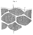
- Fig.3 shows a schematic diagram showing microporous polyolefin membrane obtained after an opening of pores by a melt stretching method.
- the numeral 1 refers to a microfibril
- 2 refers to a stacked lamella
- 3 refers to a slit-like micropore.
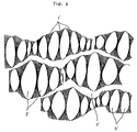
- Fig.4 shows a schematic diagram showing a hydrophilic microporous membrane of the present invention obtained after a hydrophilizing treatment of a precursor of a microporous polyolefin membrane that is subjected to an opening treatment by a melt stretching method.
- 1' refers to a microfibril bundle
- 2' refers to a stacked lamella
- 3' refers to an elliptic micropore.
- Fig.5 is a schematic diagram explaining a measuring method of a mean distance between microfibril bundles in a micropore.
- the microporous membrane of the present invention is in the range of 5 to 500 ⁇ m in thickness, and has a multilayered structure wherein the microporous layer, b-layer, providing a reinforcing function, is stacked on at least one surface of the microporous layer, a-layer, providing a separation function.
- the structure of the present invention may have a two-layered structure wherein b-layer is stacked on one surface of a-layer, or may have a three-layered structure wherein b-layer is stacked on both surfaces of a-layer.
- Both layers of a-layer and b-layer have micropores, wherein said micropores are oriented in the direction of stretching, and furthermore, said micropores are mutually interconnected either within each layer of a-layer and b-layer, or inbetween both layers of a-layer and b-layer, thereby forming stacked and interconnected micropores communicating one surface of said composite microporous membrane with the other surface thereof.
- the micropore formed in a-layer comprises microfibril bundles oriented in the direction of membrane stretching and the knotted portions of stacked lamella oriented in the direction perpendicular to the direction of membrane stretching, wherein the opening between the microfibril bundles and said knotted portions is forming elliptic micropores.
- the mean distance Da between each microfibril bundle is in the range between 0.1 and 0.8 ⁇ m, and more preferably it is in the range between 0.3 and 0.5 ⁇ m.
- a good water permeability is obtained with the microporous membrane of the present invention having the mean distance Da of 0.3 ⁇ m between each fibril bundles, and a good capability of blocking fine particles having diameters not more than 0.5 ⁇ m, which indicates a membrane of a high separation is obtained.
- the thickness of a-layer in the range between 0.5 and 20 ⁇ m, and it is more preferable to have the thickness in the range between 3 and 12 ⁇ m.
- the thickness of a-layer becomes smaller than 0.5 ⁇ m, pin-holes tend to occur in a-layer.
- the thickness of a-layer becomes larger than 20 ⁇ m, the water permeability of the composite microporous membrane tends to become smaller.
- the microporous b-layer provides a reinforcing function by supporting the microporous a-layer which provides a separation function of the composite membrane.
- the b-layer similarly to the a-layer, has a multi-layered structure of micropores oriented in the direction of membrane stretching, wherein said micropores are composed of microfibril bundles and the knotted portions of stacked lamella.
- the mean distance Db between each microfibril bundles in the range between 0.2 and 1 ⁇ m, and it is more preferable to have the mean distance in the range between 0.4 and 0.5 ⁇ m.
- a composite microporous membrane having b-layer comprising micropores having Db less than 0.2 ⁇ m is used, the rate of water permeation tends to decrease.
- Db is more than 1 ⁇ m, the mechanical strength of the composite microporous membrane having b-layer having micropores tends to decrease.
- the mean distance Lb between each knotted portion of stacked lamella of b-layer is preferably in the range between 0.4 and 4.0 ⁇ m, and more preferably in the range between 0.7 and 2.0 ⁇ m.
- Lb is more than 4.0 ⁇ m, the mechanical strength of the composite microporous membrane tends to decrease.
- the ratio of Db and Da it is necessary to have the ratio of Db and Da to be in the range of 1.3 ⁇ Db / Da ⁇ 15.
- a composite microporous membrane having the ratio of Db / Da less than 1.3 it tends to be difficult to obtain a membrane with a high water permeability and a high separation intended to be achieved in the present invention.
- the maximum pore diameter obtained by the Bubble-Point method is in the range of 0.05 to 1.0 ⁇ m.
- the rate of water permeation tends to decrease, and when the maximum pore diameter becomes larger than 1.0 ⁇ m, the mechanical strength decreases.
- An advantage of the composite microporous membrane of the present invention is a characteristic of a high flux and a high separation because the microporous membrane has the above-mentioned composite structure.
- the criteria for being high flux is to have the water permeability being not less than 0.5 l/m 2 .hr.mmHg, and more preferably not less than 1 l/m 2 .hr.mmHg when the diameter of separated particles by the membrane of the present invention is, for example, the diameter of possible blocking that is not less than 0.050 ⁇ m.
- the water permeability is preferably not less than 2 l/m 2 .hr.mmHg, and more preferably not less than 3 l/m 2 .hr.mmHg, and further preferably 5 l/m 2 .hr.mmHg. Furthermore, when the membrane is used in the range wherein the diameter of possible separation of particles by the composite microporous membrane is not less than 0.170 ⁇ m, the water permeability is preferably not less than 5 l/m 2 .hr.mmHg.
- Polymers such as polyethylene, polypropylen, poly-3-methylbutene, poly-4-methylpentene, polyvinylidene fluoride alone or mixtures of copolymers thereof can be used.
- microporous membrane of the present invention When the microporous membrane of the present invention is used in medical applications, materials having low content of soluble component in the membrane material and having blood compatibility is preferable. Furthermore, when the microporous membrane of the present invention is used in industrial applications, it is preferable to select materials so that it is possible to produce a membrane having good durability and mechanical property.
- the MI (melt index) value of polyolefin used in the present invention and obtained by a measurement according to ASTM D-1238 is in the range between 0.1 and 50, and is preferably in the range between 0.3 and 15.
- Polyolefin having MI value less than 0.1 is difficult to be formed and a desired microporous membrane can not be obtained because its viscosity when melted is too high.
- polyolefin having MI value of more than 50 it is difficult to obtain a reliable forming because of its low viscosity when melted.
- the density of a polyolefin used in the embodiment of the present invention differs depending on each material to be used, it is preferable to use a polyethylene having a density not less than 0.95 g/cm 3 , and it is preferable to use polpropylene having a density not less than 0.91 g/cm 3 .
- the composite microporous membrane of the present invention can be obtained even in a case wherein the density, ⁇ a, of polyolefin used for the formation of a-layer and the density, ⁇ b, of polyolefin used for the formation of b-layer are roughly equal.
- the composite microporous membrane of the present invention can be obtained even when MIa and MIb are equal.
- the composite microporous membrane of the present invention can be produced efficiently.
- the mean distance between each microfibril bundle of the micropores in the present invention was measured by the following method.
- the summation of b 1 to b 6 for example, of the second line is obtained.
- This process is repeated up to nth line to obtain, for example, the summation of n 1 to n 6 .
- the value of total sum (total distance) is obtained from these values.
- the total number of micropores (total number) intersecting each line is obtained to calculate the mean distance Da, Db by dividing the total distance by the total number.
- the method to obtain the composite microporous membrane of the present invention comprises, initially making a precursor of a composite microporous . membrane which is an intermediary, followed by subjecting to a coating treatment by using hydrophilic copolymer. Said precursor may be obtained by forming a membrane by using a composite spinning method followed by selecting a polyolefin that meets the above requirements.
- a nozzle having more than two tubular nozzles provided in a cocentrical manner is preferably used.
- the spinning temperature should not be less than the melting temperature of polyolefin (preferably 10 to 100°C higher than the melting temperature).
- the extruded polymer is drawn at a reel speed of 0.1 to 3 m/sec. in an atmosphere at a temperature of 10 to 40°C.
- the muli-layered material obtained therefrom is subjected under an as-is condition to a heat treatment to form stacked lamella or to a heat treatment at a temperature (preferably at a temperature 5 to 50°C lower than the melting temperature) not lower than the melting temperature of polyolefin, followed by being subjected to stretching to obtain openings in the multi-layered body.
- the stretching is preferably done by a cold stretching followed subsequently by a hot stretching.
- the cold stretching is a process wherein microcracks are induced between stacked lamella by causing a structural failure of the multi-layered body at a relatively low temperature.
- This cold stretching is preferably carried out in a temperature range between 0 °C and a temperature 50°C lower than the melting point of the polyer.
- this temperature for cold stretching is in the range between 0 and 80°C, and preferably in the range between 10 and 50°C.
- the cold stretching magnification is preferably from 5 to 100%. When this magnification is not more than 5%, the microcracks are not fully developed and thus intended pore diameters are not easily obtained. On the other hand, when this magnification is not less than 100%, too many microcracks are developed and thus intended large pore diameters are not easily obtained in the supporting layer (b layer).
- the subsequent hot stretching is a process wherein the membrane is made into a microporous membrane having micropores of slit-like shape by enlarging microcracks developed in the multi layered body, followed by forming microfibrils between stacked lamella.
- the hot stretching temperature should not be higher than the melting temperature of polyolefin, and the hot stretching should be carried out at a temperature as high as possible.
- the hot stretching magnification may be appropriately selected for each intended pore diameter, and it may be in the range between 50 and 2000%, and it may preferably be in the range between 100 and 1000% to have a reliable production process.
- the membrane thus obtained is further subjected to a hot setting, wherein the membrane is kept under a constant length or under a slightly creeped condition, to have a dimensional stability of the precursor of microporous membrane.
- the temperature of the hot setting should not be less than the stretching temperature, and should preferably be not more than the melting temperature.
- the precursor of the muli-layered composite membrane thus obtained is further subjected to a process to render a permanent hydrophilic property.
- the hydrophilic copolymer used in the present invention may be composed of a copolymer having not less than 20% by mole of ethylene and not less than 10% by mole of hydrophilic monomer. Any type of copolymer selected from copolymers such as randomly oriented copolymer, blocked-copolymer and grafted-copolymer may be used.
- the content of ethylene in the copolymer is less than 20% by mole, it is not preferable because the copolymer does not provide a sufficient affinity to the precursor, and whereby precursor can not be coated by the hydrophilic copolymer at the ratio of 3 to 30% by weight for 100% by weight of precursor by immersing the precursor in a solution of hydrophilic copolymer.
- vinyl compounds such as vinyl alcohol, (meta)acrylic acid and its salts, hydroxylethyl(meta)acrylate, polyethylenegrycol(meta)acrylic ester, vinylpyrrolidone and acrylamide may be used. Any vinyl compounds may be used as long as more than one kind of hydrophilic monomer is contained, and vinyl alcohol may be preferably used as the monomer.
- the hydrophilic copolymer used in the present invention may contain a third component other than either ethylene or hydrophilic monomer, wherein said third component may be acetic vinyl, (meta)acrylic ester, vinyl alcoholic fatty ester, formal or butylar derivative of vinyl alcohol and the like.
- the amount of coating of the hydrophilyc copolymer on the precursor of microporous membrane should be in the range between 3 to 30% by weight in terms of precursor's weight. When said amount is less than 3% by weight, a sufficient hydrophilic property of the microporous membrane can not be obtained, and thereby water is insufficiently permeated into the microporous membrane. On the other hand, when said amount exceeds 30% by weight, the micropores in the membrane tend to be clogged by the copolymer, whereby the permeability tends to be reduced.
- the solvent for the copolymer used in the present invention is preferably a water soluble organic solvent, comprising alcohols, such as methanol, ethanol, n-propanol, isopropylalchol, or dimethylsulphoxide, dimethylformamide and the like. These solvents may be used alone, but they are more preferably used in a mixture with water because the mixture provides a higher solubility to a hydrophilic copolymer.
- alcohols such as methanol, ethanol, n-propanol, isopropylalchol, or dimethylsulphoxide, dimethylformamide and the like.
- a mixed solvent comprising water and alcohols having a boiling point less than 100 °C, such as methanol, ethanol,and isopropylalchol may be most preferably used thereby providing ease of making an environment having solvent vapor used in the process of drying the microporous membrane covered by the hydrophilic copolymer, in another words, a low solvent vapor pressure, and consequently thereby providing low toxicity to human beings.
- the mixing ratio of the water soluble solvent to water may be selected at any ratio as long as the permeability into the precursor is not impeded and the solubility of the copolymer is not decreased. It may depend on the type of copolymer used, and the ratio of ethanol to water is preferably in the range between 90/10 and 30/70 (% by volume) when ethanol is used as an organic solvent.
- the concentration of hydrophilic copolymer should be roughly in the range between 0.1 and 10% by weight, and it should preferably be in the range of 0.5 to 5% by weight. It is difficult to coat evenly with a hydrophilic copolymer when the precursor is treated by a solution having a concentration of less than 0.1% by weight. On the other hand, when the concentration is more than 10% by weight, the viscosity of the solution becomes too high, whereby micropores of the multi-layered membrane are clogged by the copolymer when the precursor is treated using said solution.
- the method of immersing the precursor in the hydrophilic copolymer solution either method of immersing the precursor more than twice in a copolymer solution with the same concentration of copolymer or of immersing the precursor more than twice in a copolymer solution with different concentration of copolymer.
- the duration of the immersion treatment depends on such factors as the membrane thickness, the diameter of micropores and porosity of the precursor, and it is preferably in the range between a few seconds and a few minutes.
- the precursor After being immersed in the hydrophilic copolymer solution, and before being subjected to a drying treatment, the precursor needs to be subjected to a setting process after being left for at least 30 seconds in an atmosphere having not less than 3% by volume of the organic solvent vapor, and being set at a temperature between the room temperature and a temperature below the boiling point of said solvent.
- the objective of this treatment is to eliminate any clogging of micropores by a coating membrane being formed on the surface of microfibrils and knotted portions of the stacked lamella, both of these are composing the precursor.
- a further objective of this treatment is to form elliptic micropores by bundling microfibrils, thereby enlarging the slit-like micropores to increase the water permeability and to increase the affinity to the water to be treated.
- the evaporation speed of the solvent from the precursor during said setting process is preferable to keep the atmosphere of the setting process close to an atmosphere having a saturated vapor concentration of the solvent.
- the setting temperature low.
- the temperature of said atmosphere should preferably be kept at not less than the room temperature and not more than the boiling point of the water miscible solvent.
- the precursor after the immersion operation may be raised from the immersion bath into said atmosphere at a preferable angle ranging from 45°to 90°.
- the amount of dripping depends on such factors as raising speed of the precursor form the immersion bath, the viscosity of immersion solution and the raising speed of the precursor from the surface of immersion bath.
- guides or slits and the like may be employed to wipe off the solution from the surface of precursor.
- At least a duration of 30 seconds is required for this setting process.
- a condensation of copolymer solution due to the evaporation of solvent from the precursor and a homogenizing of the membrane through migration at the surface of stacked lamella and microfibrils may be effectuated.
- precursor is subjected to a continuous treatment using hydrophilic solution, it is required to keep the duration of this setting process for not less than 30 seconds.
- the duration of setting for less than 30 seconds results in insufficient condensation of the solvent by evaporation, whereby a condition may occur wherein the precursor is subjected to drying with an excess amount of solution being left on the precursor, which may cause the clogging of micropores by hydrophilic copolymer, and while the homogeneous setting of copolymer in the membrane structure being insufficient, thereby causing it difficult to obtain microporous membrane with a high water permeability and a high separation capability.
- the amount of solvent evaporation from the precursor when the duration of setting is for 30 seconds, is preferably from roughly 15 to 30% of the used hydrophilic copolymer solution.
- such method as controlling the temperature of atmosphere for setting and venting air or insert gas into said atmosphere.
- Drying of the precursor after being subjected to a setting process may be effectuated by using any of known drying methods such as vacuum drying and hot air drying.
- the drying temperature may be at any temperature as long as the composite microporous membrane may not be deformed by the heat.
- a composite microporous polyethylene membrane may be preferably dried at a temperature not higher than 120 °C, and it may be most preferably dried at a temperature from 40 to 70°C.
- the amount of adhesion of hydrophilic copolymer to the precursor of composite microporous membrane is roughly from 1 to 30% by weight, more preferably from 3 to 15% by weight of the weight of precursor of composite microporous membrane working as a substrata.
- microfibrils (refer to Fig.3-1) in the precursor of microporous membrane are bundled together by this coating treatment by hydrophilic copolymer, thereby forming microfibril bundles (refer to Fig.4-1') and the slit-like micropores (refer to Fig.3-3) transforming into elliptic micropores (refer to Fig.4-3').
- a high density polyethylene having a melt index (MI) of 5.5 and a density of 0.968g/cm 3 Hizex 2200 J, from Mitsui Oil & Chemical Co., Ltd.
- 21% by weight of a high density polyethylene having a MI value of 0.35 and a density of 0.968g/cm 3 (BU004N, from Mitsubishi Chemicals Co., Ltd) and 15% by weight of a low density polyethylene having a MI value of 8.0 and a density of 0.920g/cm 3 (Ultzex 20200 J, from Mitsui Oil & Chemical Co., Ltd.) were hot mixed by using a twin screw extruder at a temperature of 180 °C to obtain a blended polymer having a MI value of 5.2 and a density of 0.961 g/cm 3 .
- This blended polymer was used as a polymer to form a-layer, and the above-mentioned high density polyethylene having a MI value of 5.5 and a density of 0.968g/cm 3 was used as a polymer to form b-layer, whereby these polymers were melt-spinned by using a nozzle for manufacturing hollow fibers at a temperature of 158°C and at a reel speed of 80m/min, wherein the nozzle has two tubular nozzles provided in a concentric manner.
- said blended polymer and said high density polyethylene were extruded from the outer nozzle and the inner nozzle, respectively, under a condition where these polymers were extruded at an extrusion ratio of 1/5, at a line speed of 3.01 cm/min., and at a draft ratio of 2560. Furthermore, the composite hollow fiber before stretching was obtained by reeling up the extruded fiber from the nozzle while a cooling air having a temperature of 20 °C and air speed of 3.0m/sec. being blown uniformly around the fiber.
- the hollow fiber thus obtained before stretching was subjected to an annealing treatment for 12 hours while being set at a constant length in an atmosphere kept at 115 °C.
- a precursor of composite microporous hollow fiber membrane was obtained by cold-stretching the annealed fiber by 80% while subjecting the fiber to a roller kept at 30 °C, and subsequently hot-stretching the cold-stretched fiber so that the total amount of stretching becomes 400% in a roller in an oven kept at 108 °C, and further subjecting to a hot setting thereby relieving the stretching by 25% of the total amount of stretching in a hot chamber kept at 115°C
- the above-mentioned precursor was immersed in the solution thus obtained for a duration of 150 seconds, followed by being raised, then a part of the hydrophilyzing solution being extensively adhered on the surface of said composite hollow fiber was ringed off by a guide.
- the precursor was raised at a rising angle of 90 ° in an atmosphere having an ethanol vapor concentration of 40% by volume and a temperature of 60°C, thereby uniformly coating the inner surface of micropores of the precursor by the hydrophilyzing solution while the precursor being left still for a duration of 360 seconds, followed by drying the solution by a hot air having a temperature of 60 °C.
- the coating rate of ethylene-vinyl alcohol copolymer on the hydrophlilyzed hollow fiber membrane thus obtained was 8.7% by weight.
- the blended polymer was melt spinned from a nozzle for manufacturing hollow fibers having two tubular nozzles provided in a concentric manner at a extrusion temperature of 180°C and at a reel speed of 35m/min. to provide a polymer for a-layer and while above-mentioned high density polyethylene having a density of 0.968g/cm 3 and a MI calue of 0.35 was extruded to prove a polymer for b-layer.
- the blended polymer was extruded form the outer nozzle and the above-mentioned high density polyethylene was extruded, respectively, at a extrusion ratio of 1/5, at a total extrusion volume of 7.5 cc/min.nozzle, at an extrusion line speed of 57cm/min., and at a draft ratio of 75.
- a composite hollow fiber before stretching was obtained by reeling up the fiber by uniformly subjecting the surface of the fiber being extruded from the nozzle to a cooling air having a temperature of 20°C and an air speed of 0.5 m/sec.
- the hollow fiber thus obtained was subjected to a heat treatment for a duration of 16 hours in a air having a temperature of 125°C while the hollow fiber remaining on a bobbin.
- the annealed fiber was further subjected to a cold stretching of 16% in rollers kept at 30 °C, followed by being subjected to hot stretching in rollers in a oven kept at 119°C to have the total stretching of 400%.
- the annealed fiber was further subjected to a heat setting at a constant length in a oven kept at 123°C to have a tow layered precursor of composite microporous hollow fiber membrane.
- the above-mentioned precursor was immersed in the solution thus obtained for a duration of 30 seconds, followed by being raised, then a part of the hydrophilyzing solution being extensively adhered on the surface of said precursor was wringed off by a guide.
- the precursor was raised at a rising angle of 90° in an atmosphere having an ethanol vapor concentration of 40% by volume and a temperature of 60 °C, while uniformly coating the inner surface of micropores of the precursor by the hydrophilyzing solution while the precursor being left still for a duration of 80 seconds, followed by drying the solution by a hot air having a temperature of 70°C.
- the coating rate of ethylene-vinyl alcohol copolymer on the hydrophlilic hollow fiber membrane thus obtained was 10.5% by weight.
- both outer and inner surfaces, and also the surface of micropores of said composite microporous hollow fiber membrane were uniformly coated by a thin film of ethylene-vinyl alcohol copolymer.
- the mean distance between each fibril bundle of micropores in the inner layer (b-layer) was 0.54 ⁇ m, and that of micropores in the outer layer (a-layer) was 0.35 ⁇ m.
- the ratio of Db/Da of the same membrane was 1.54, and the thickness of the outer layer providing the separation function was 8 ⁇ m.
- Fig. 2 shows a photo of the membrane thus obtained under a transmission electron microscope, and Table 1 shows the membrane characteristics of the membrane thus obtained.
- a high density polyethylene having a density of 0.965g/cm 3 and a MI value of 0.9 (HY01, from Idemitu Oil & Chemical Co., Ltd.) to be formed into a-layer was extruded from the middle extrusion nozzle at an extrusion rate of 0.375g/min.
- a high density polyethylene having a density of 0.968g/cm 3 and a MI value of 5.5 (Hizex 2200 J) to be formed into b-layer was extruded from both an outermost and an innermost extrusion nozzle at an extrusion rate of 7.5g/min.
- the temperature of extrusion was 160°C and the reel speed was 100m/min.
- the hollow fiber thus obtained before stretching was subjected to a heat treatment for a duration of 12 hours in an air having a temperature of 115 °C while the hollow fiber being left on a bobbin.
- the heat treated fiber was further subjected to a cold stretching by 80% in rollers kept at a temperature of not more than 30°C, subsequently followed by being subjected to hot stretching in rollers in a oven kept at 107°C to have a total stretching of 400%.
- the fiber thus obtained was further subjected to a hot setting thereby relieving the stretching by 225% of the total amount of stretching in an oven kept at 120°C to have a multi-layered precursor of composite microporous membrane.
- said multilayered membrane was raised at a rising angle of 90 ° in an atmosphere having an ethanol vapor concentration of 40% by volume and a temperature of 60 °C, while the membrane being left for a duration of 80 seconds, followed by drying the solution by a hot air having a temperature of 55 °C, to continuously obtain hydrophilized microporous membrane.
- a hydrophilic microporous membrane was obtained in a condition similar to that of example 1 except that the hot stretching was carried out at a temperature of 113°C.
- a high density polyethylene having a density of 0.968g/cm 3 and a MI value of 5.5 Hizex 2200 J, from Mitsui Oil & Chemical Co., Ltd.
- a polyethylene having a density of 0.960g/cm 3 and a MI value of 0.9 Nissan 2010, from Nissan Chemical Co,.
- a composite hollow fiber before stretching was further obtained by reeling up the extruded fiber from the nozzle at a reel rate of 205 m/min. while a cooling air having a temperature of 16 °C and an air speed of 1.0m/sec. being blown uniformly around the fiber.
- the hollow fiber thus obtained before stretching was subjected to an annealing treatment for 12 hours while being kept at a constant length in an atmosphere heated to a temperature of 115°C.
- a precursor of composite microporous hollow fiber membrane was obtained by a cold stretching of the annealed fiber by 80% while subjecting the fiber to a roller kept at 30 °C, and followed by a hot stretching of the cold-stretched fiber so that the total amount of stretching becomes 350% and by further subjecting to a hot setting at a constant length for 1 minute in a oven heated to 115°C.
- a hydrophlyzing treatment was carried out on the precursor under the same conditions used in example 1.
- This blended polymer was used as a polymer to form a-layer, and the above-mentioned high density polyethylene having a MI value of 0.25 and a density of 0.961g/cm 3 was used as a polymer to form b-layer, whereby these polymers were melt spinned through a nozzle having two tubular nozzles provided in a concentric manner at a temperature of 200°C and at a reel speed of 35m/min.
- said blended polymer and said polyethylene having a density of 0.961g/cm 3 was extruded from an outer nozzle and an inner nozzle, respectively, at a condition where these polymers were extruded at an extrusion ratio of 1/6, at an extrusion line speed of 57cm/min., and at a draft ratio of 75. Furthermore, a composite hollow fiber before stretching was obtained by reeling up the extruded fiber from the nozzle while a cooling air having a temperature of 30 °C and air speed of 0.5m/sec. being blown uniformly around the fiber.
- the hollow fiber thus obtained before stretching was subjected to an annealing treatment, a stretching treatment, and hydrophilyzing treatment under the same condition as that of example 2, to obtain a composite microporous hollow fiber membrane.
- polypropylene having a density of 0.91g/cm 3 and a MI value of 1.0 was extruded to provide a polymer forming b-layer as an inner layer
- a high density polyethylene having a density of 0.965g/cm 3 and a MI value of 0.9 was extruded to provide a polymer forming a-layer as an outer layer, at an extrusion rate of 1.1g/min. for the inner layer and at an extrusion rate of 22.5g/min. for the outer layer, respectively.
- An extrusion temperature of 210 °C and a reel speed of 30m/min. were employed.
- a precursor of a composite microporous membrane was obtained after a heat treatment and a stretching treatment under the same conditions as those of example 1 except for the aforementioned conditions.
- said multilayered membrane was raised at a rising angle of 90 ° in an atmosphere having an ethanol vapor concentration of 40% by volume and a temperature of 60 °C, while the membrane being left for a duration of 360 seconds, followed by drying the solution by a hot air having a temperature of 55 °C, to obtain a continuously hydrophylized composite microporous hollow fiber membrane.
- the membrane characteristics of the membrane thus obtained are shown in Table 1.
- the membrane characteristics of membrane thus obtained are shown in Table 1.
- a composite microporous hollow fiber membrane was obtained under the same conditions as those of example 2 except that an extrusion ratio of the outer layer and the inner layer of 1/4 during a spinning and the total extrusion rate of 3.0cc/min.nozzle were employed.
- a high density polyethylene having a density of 0.968g/cm 3 and a MI value of 5.5 was extruded at an extrusion rate of 7.8g/min.
- the extrusion temperature was 160°C, and a reel speed of 100m/min. was employed.
- the hollow fiber thus obtained before stretching was subjected to a heat treatment for a duration of 12 hours in an air having a temperature of 115 °C while the hollow fiber remaining on a bobbin.
- the heat treated fiber was further subjected to a stretching of 80% in rollers kept at a temperature of not more than 30 °C, followed by being subjected to a hot stretching in rollers in a oven heated to a temperature of 95 °C to have the total stretching of 300%.
- the heat treated hollow fiber was further subjected to a hot setting while the stretching being at 25% less than the total stretching in a oven heated to 120°C to have a porous membrane.
- a hydrophilyzing treatment was employed in the same manner as that of example 1.
- the membrane characteristics of microporous hollow fiber membrane thus obtained are shown in Table 1.
- a microporous hollow fiber membrane was obtained in the same manner as that of example 1 except that a stretching temperature of 107°C was employed.
- a microporous membrane was obtained in the same manner as that of comparison 1 except that a total stretching of 400% and a temperature of 110°C were employed.
- the membrane characteristics of the microporous membrane thus obtained are shown in Table 1.
- polypropylene having a density of 0.91g/cm 3 and a MI value of 1.0 was extruded at an extrusion rate of 9.0g/min. and at an extrusion temperature of 200 °C, and a reel speed of 580 m/min. was employed.
- the hollow fiber thus obtained before stretching was subjected to a cold stretching by 26% in rollers kept at a temperature of not more than 30 °C, followed by a hot stretching in rollers in a oven heated to 140 °C to have a total stretching of 122%.
- the heat treated fiber was further subjected to a hot setting while the stretching being 22% less than the total stretching in a oven heated to 143 °C to have a precursor of microporous membrane.
- the same hydrophilyzing treatment as that of example 1 was employed.
- the membrane characteristics of microporous membrane thus obtained are shown in Table 1.
- the microporous membrane of the present invention is a hydrophilic composite microporous membrane having a high separation, a high flux, a high membrane strength and a permanent hydrophilic characteristic. Furthermore, a layer having mainly micropores to provide a separation function can be provided at any position along the cross section of the membrane, thereby making the membrane suitable for filtration of various solutions that needs to be treated.
Landscapes
- Chemical & Material Sciences (AREA)
- Chemical Kinetics & Catalysis (AREA)
- Engineering & Computer Science (AREA)
- Mechanical Engineering (AREA)
- Inorganic Chemistry (AREA)
- Manufacturing & Machinery (AREA)
- Separation Using Semi-Permeable Membranes (AREA)
- Laminated Bodies (AREA)
- Manufacture Of Porous Articles, And Recovery And Treatment Of Waste Products (AREA)
Claims (11)
- Mikroporöse Polyolefinkompositmembran, worin eine mikroporöse b-Lage, die eine verstärkende Wirkung bereitstellt, an wenigstens eine Oberfläche einer mikroporösen a-Lage, die eine Trennwirkung bereitstellt, gebunden ist, und wobei sowohl die a-Lage als auch die b-Lage einen viellagigen Körper mit Mikroporen umfaßt, wobei die Mikroporen von einer Oberfläche zur anderen Oberfläche der mikroporösen Kompositmembran miteinander verbunden sind, dadurch gekennzeichnet, daß die Mikroporen elliptisch sind und ferner eine Vielzahl an Mikrofibrillenbündeln und verknoteten Teilen aus gestapelter Lamelle, die an beide Enden der Mikrofibrillenbündel gebunden ist, umfassen, wobei die Mikrofibrillenbündel und die verknoteten Teile der gestapelten Lamelle, die die Mikroporen der mikroporösen Membran bilden, mit 3 bis 30 Gew.% eines hydrophilen Copolymers pro 100 Gew.% eines Precursors der mikroporösen Kompositmembran überzogen sind, und wobei das Verhältnis des mittleren Abstands Da zwischen den Mikrofibrillenbündeln in Mikroporen, die in der a-Lage vorliegen, zum mittleren Abstand Db zwischen den Mikrofibrillenbündeln in Mikroporen, die in der b-Lage vorliegen, im Bereich von 1,3 ≤ Db/Da ≤ 15 ist, worin Da in dem Bereich zwischen 0,1 und 0,8 µm ist, Db in dem Bereich zwischen 0,2 und 1 µm ist, und worin der maximale Porendurchmesser, erhalten durch das Bubble-Point-Verfahren, von 0,05 bis 1,0 µm ist.
- Mikroporöse Polyolefinkompositmembran gemäß Anspruch 1, wobei der mittlere Abstand Lb zwischen den verknoteten Teilen gestapelter Lamelle, die in der b-Lage vorliegt, von 0,4 bis 4,0 µm ist.
- Mikroporöse Polyolefinkompositmembran gemäß Anspruch 1 oder 2, wobei das hydrophile Copolymer ein Copolymer vom Typ Ethylen-Vinylalkohol ist.
- Mikroporöse Polyolefinkompositmembran gemäß Anspruch 2, wobei ein Copolymer mit 20 bis 90 Mol% Ethyleneinheiten, von 10 bis 80 Mol% Vinylalkoholeinheiten und nicht mehr als 50 % Einheiten eines anderen Monomers als hydrophiles Copolymer verwendet wird.
- Mikroporöse Polyolefinkompositmembran gemäß einem oder mehreren der Ansprüche 1 bis 4, wobei die mikroporöse Polyolefinkompositmembran eine Hohlfasermembran mit einem inneren Durchmesser von 5 bis 5.000 µm und einer Membrangesamtdicke von 5 bis 500 µm ist, während die Membrandicke der a-Lage nicht weniger als 0,5 µm und nicht mehr als 1/3 der Membrangesamtdicke aufweist.
- Verfahren zur Herstellung einer mikroporösen Polyolefinkomposit-Hohlfasermembran, definiert wie in einem der Ansprüche 1 bis 5, umfassend die Schritte aus:wobei MIa und MIb in einer Beziehung MIa < MIb stehen, wobei pa und pb in einer Beziehung ρa < ρb stehen, wodurch sowohl die a-Lage als auch die b-Lage einen Schichtkörper aus schlitzartigen Mikroporen umfassen, ferner umfassend eine Anzahl an Mikrofibrillen und verknoteten Teilen gestapelter Lamelle, die an beiden Enden der Mikrofibrillen gebunden ist;Strecken einer Kompositmembran, erhalten durch ein Kompositschmelzspinnen nach Zuführen von Polyolefin mit einem Schmelzindexwert von MIb und/oder einer Dichte von ρb, um eine mikroporöse Lage, b-Lage, zu bilden, die eine verstärkende Wirkung bereitstellt, zu wenigstens einer der Düsen zur Herstellung von hohlen Fasern, wobei die Düse nicht weniger als zwei in einer konzentrischen Weise angeordnete röhrenförmige Düsen aufweist;Zuführen von Polyolefin mit einem Schmelzindexwert von MIa und/oder eine Dichte von ρa, um eine mikroporöse Lage, a-Lage, zu bilden, die eine Trennwirkung bereitstellt, zu einer Düse, angeordnet entweder an einer Seite oder in der Mitte einer für die b-Lage bereitgestellten Düse,
Eintauchen eines Hohlfaser-membranartigen Precursors mit den Mikroporen, die von einer Oberfläche der Membran zu ihrer anderen Oberfläche verbunden sind, in eine organische Lösung, die durch Lösen eines hydrophilen Copolymers in einem organischen Lösungsmittel erhalten wird;
Hochziehen des Precursors;
für nicht weniger als 30 Sekunden in einer Atmosphäre mit 3 Vol.% des Dampfes des organischen Lösungsmittels lassen und bei einer Temperatur zwischen Raumtemperatur und nicht mehr als dem Siedepunkt des organischen Lösungsmittel; dann einem Trocknen unterwerfen;
wodurch eine Hohlfaser-Membran mit verknoteten Teilen gestapelter Lamelle und Mikrofibrillenbündeln erhalten wird, die mit 3 bis 30 Gew.% eines hydrophilen Copolymers pro 100 % des getrockneten Gewichts des Precursors überzogen sind. - Verfahren zur Herstellung einer mikroporösen Polyolefinkomposit-Hohlfasermembran gemäß Anspruch 6, wobei das hydrophile organische Lösungsmittel oder eine Mischung des hydrophilen organischen Lösungsmittels und Wasser als organisches Lösungsmittel verwendet wird.
- Verfahren zur Herstellung einer mikroporösen Polyolefinkomposit-Hohlfasermembran gemäß Anspruch 7, wobei Alkohol mit einem Siedepunkt von nicht mehr als 100°C als hydrophiles organisches Lösungsmittel verwendet wird.
- Mikroporöse Polyolefinkomposit-Hohlfasermembran, erhalten durch das Verfahren gemäß Anspruch 6, wobei das Verhältnis des mittleren Abstands Da zwischen den Mikrofibrillenbündeln der Mikroporen in der a-Lage zu dem mittleren Abstand Db zwischen den Mikrofibrillenbündeln der Mikroporen in der b-Lage im Bereich von 1,3 ≤ Db/Da ≤ 15 ist.
- Mikroporöse Polyolefinkomposit-Hohlfasermembran, erhältlich durch das Verfahren gemäß Anspruch 6, wobei der mittlere Abstand Db zwischen den Mikrofibrillenbündeln der Mikroporen in der b-Lage 0,2 bis 1 µm ist.
- Mikroporöse Polyolefinkompositmembran gemäß Anspruch 1, wobei der Durchmesser blockierbarer Partikel nicht geringer als 0,050 µm ist und der Grad an Wasserdurchlässigkeit nicht geringer als 0,5 l/m2·hr·mmHg ist.
Applications Claiming Priority (4)
| Application Number | Priority Date | Filing Date | Title |
|---|---|---|---|
| JP3298/94 | 1994-01-17 | ||
| JP329894 | 1994-01-17 | ||
| JP329894 | 1994-01-17 | ||
| PCT/JP1995/000043 WO1995019219A1 (en) | 1994-01-17 | 1995-01-17 | Composite microporous polyolefin film and process for producing the same |
Publications (3)
| Publication Number | Publication Date |
|---|---|
| EP0740952A1 EP0740952A1 (de) | 1996-11-06 |
| EP0740952A4 EP0740952A4 (de) | 1999-08-18 |
| EP0740952B1 true EP0740952B1 (de) | 2002-12-11 |
Family
ID=11553473
Family Applications (1)
| Application Number | Title | Priority Date | Filing Date |
|---|---|---|---|
| EP95906482A Expired - Lifetime EP0740952B1 (de) | 1994-01-17 | 1995-01-17 | Mikroporöser polyolefinverbundfilm und verfahren zur dessen herstellung |
Country Status (5)
| Country | Link |
|---|---|
| US (1) | US5863645A (de) |
| EP (1) | EP0740952B1 (de) |
| KR (1) | KR100346589B1 (de) |
| DE (1) | DE69529151T2 (de) |
| WO (1) | WO1995019219A1 (de) |
Cited By (1)
| Publication number | Priority date | Publication date | Assignee | Title |
|---|---|---|---|---|
| CN102140734A (zh) * | 2011-01-10 | 2011-08-03 | 武汉理工大学 | 一种增强型双组分纳米纤维多孔膜及制备方法 |
Families Citing this family (20)
| Publication number | Priority date | Publication date | Assignee | Title |
|---|---|---|---|---|
| JPH11253768A (ja) * | 1998-03-13 | 1999-09-21 | Mitsubishi Rayon Co Ltd | 複合化中空糸膜およびその製造方法 |
| JPH11262764A (ja) * | 1998-03-16 | 1999-09-28 | Mitsubishi Rayon Co Ltd | 浄水器 |
| US6673057B1 (en) * | 1998-06-29 | 2004-01-06 | The Procter & Gamble Company | High flux liquid transport members comprising two different permeability regions |
| US20040029952A1 (en) * | 1999-09-03 | 2004-02-12 | Yung-Ming Chen | Ethylene vinyl alcohol composition and coating |
| US6395325B1 (en) * | 2000-05-16 | 2002-05-28 | Scimed Life Systems, Inc. | Porous membranes |
| DE10040778C2 (de) * | 2000-08-21 | 2002-11-21 | Daramic Inc | Fische anlockende Duft-und Lockkörper auf Basis von porösem, thermoplastischen Kunststoff |
| US6689501B2 (en) | 2001-05-25 | 2004-02-10 | Ballard Power Systems Inc. | Composite ion exchange membrane for use in a fuel cell |
| ATE395127T1 (de) * | 2003-03-05 | 2008-05-15 | Hydranautics | Tauchbares membranmodul mit austauschbaren membranelementen |
| US20050129968A1 (en) * | 2003-12-15 | 2005-06-16 | Henkel Consumer Adhesives, Inc. | Embossed film with adhesive or without adhesive or laminated to bottom non-slip surface to simulate a leather or linen texture for lining shelves and drawers |
| US20050130518A1 (en) * | 2003-12-15 | 2005-06-16 | Henkel Consumer Adhesives, Inc. | Embossed film with adhesive or without adhesive or laminated to bottom non-slip surface to simulate metal textures for lining shelves and drawers |
| US20050129894A1 (en) * | 2003-12-16 | 2005-06-16 | Henkel Consumer Adhesives, Inc. | Flexible plastic or vinyl sheeting coated with adhesive for refinishing |
| EP1921702A1 (de) | 2006-11-10 | 2008-05-14 | DSMIP Assets B.V. | Befeuchtungsmembran |
| DE102007019051B3 (de) * | 2007-04-23 | 2008-10-09 | Fresenius Medical Care Deutschland Gmbh | Hohlfaserkapillarmembran und Verfahren zu deren Herstellung |
| CN102489173A (zh) * | 2011-11-18 | 2012-06-13 | 天津膜天膜科技股份有限公司 | 一种异质复合中空纤维膜的制备方法 |
| JP7255945B2 (ja) * | 2019-03-14 | 2023-04-11 | 帝人株式会社 | 親水性複合多孔質膜 |
| JP7276688B2 (ja) * | 2019-08-29 | 2023-05-18 | トヨタ自動車株式会社 | エチレン-ビニルアルコール共重合体の多孔質体の製造方法 |
| JP7240608B2 (ja) | 2019-08-29 | 2023-03-16 | トヨタ自動車株式会社 | 非水溶性高分子の多孔質体の製造方法 |
| WO2022089521A1 (zh) * | 2020-10-28 | 2022-05-05 | 中国石油化工股份有限公司 | 一种重油加氢反应系统及重油加氢方法 |
| CN115403815B (zh) * | 2022-10-08 | 2023-05-12 | 郑州大学 | 一种具有取向泡孔的微孔泡沫材料的制备方法 |
| CN118477498B (zh) * | 2024-07-11 | 2024-10-18 | 阿克菲姆膜材(嘉兴)有限公司 | 一种长效抗污堵高气体渗透性的聚4-甲基-1-戊烯膜制备方法及用途 |
Family Cites Families (10)
| Publication number | Priority date | Publication date | Assignee | Title |
|---|---|---|---|---|
| US4530809A (en) * | 1980-10-14 | 1985-07-23 | Mitsubishi Rayon Co., Ltd. | Process for making microporous polyethylene hollow fibers |
| JPS5766114A (en) * | 1980-10-14 | 1982-04-22 | Mitsubishi Rayon Co Ltd | Porous polyethylene hollow fiber and its production |
| JPS57117951A (en) * | 1981-01-16 | 1982-07-22 | Mitsubishi Rayon Co | Porous polyethylene film and its manufacture |
| US5084173A (en) * | 1985-05-27 | 1992-01-28 | Asahi Medical Co., Ltd. | Hydrophilic composite porous membrane, a method of producing the plasma separator |
| JPS6244060A (ja) * | 1985-08-20 | 1987-02-26 | Shibaura Eng Works Co Ltd | ステツピングモ−タ |
| US4808315A (en) * | 1986-04-28 | 1989-02-28 | Asahi Kasei Kogyo Kabushiki Kaisha | Porous hollow fiber membrane and a method for the removal of a virus by using the same |
| JPS62269706A (ja) * | 1986-05-16 | 1987-11-24 | Mitsubishi Rayon Co Ltd | ポリオレフイン多孔質中空糸複合膜及びその製法 |
| JPH022849A (ja) * | 1987-06-26 | 1990-01-08 | Ube Ind Ltd | 多孔性中空糸膜 |
| JPH0657143B2 (ja) * | 1988-03-01 | 1994-08-03 | 宇部興産株式会社 | 菌体濃縮分離用モジュール |
| JPH0370539A (ja) * | 1989-08-11 | 1991-03-26 | Nippon Kapuseru Prod:Kk | 診断用サーモグラフィー装置 |
-
1995
- 1995-01-17 EP EP95906482A patent/EP0740952B1/de not_active Expired - Lifetime
- 1995-01-17 DE DE69529151T patent/DE69529151T2/de not_active Expired - Fee Related
- 1995-01-17 WO PCT/JP1995/000043 patent/WO1995019219A1/ja not_active Ceased
- 1995-01-17 US US08/676,255 patent/US5863645A/en not_active Expired - Lifetime
- 1995-01-17 KR KR1019960703830A patent/KR100346589B1/ko not_active Expired - Fee Related
Cited By (2)
| Publication number | Priority date | Publication date | Assignee | Title |
|---|---|---|---|---|
| CN102140734A (zh) * | 2011-01-10 | 2011-08-03 | 武汉理工大学 | 一种增强型双组分纳米纤维多孔膜及制备方法 |
| CN102140734B (zh) * | 2011-01-10 | 2012-12-19 | 武汉理工大学 | 一种增强型双组分纳米纤维多孔膜及制备方法 |
Also Published As
| Publication number | Publication date |
|---|---|
| DE69529151D1 (de) | 2003-01-23 |
| EP0740952A1 (de) | 1996-11-06 |
| US5863645A (en) | 1999-01-26 |
| KR100346589B1 (ko) | 2002-12-05 |
| DE69529151T2 (de) | 2003-09-11 |
| WO1995019219A1 (en) | 1995-07-20 |
| EP0740952A4 (de) | 1999-08-18 |
Similar Documents
| Publication | Publication Date | Title |
|---|---|---|
| EP0740952B1 (de) | Mikroporöser polyolefinverbundfilm und verfahren zur dessen herstellung | |
| EP0037836B1 (de) | Hohlfaser-mikrofilter aus polyvinyliden-fluoridharz und verfahren zu seiner herstellung | |
| US10850239B2 (en) | Filter medium, method for manufacturing same, and filter module comprising same | |
| EP0050399B1 (de) | Mikroporöse Polyäthylen-Hohlfäden und Verfahren zu ihrer Herstellung | |
| US5376273A (en) | Supported microporous membrane | |
| US6074718A (en) | Self supporting hollow fiber membrane and method of construction | |
| DE3878326T3 (de) | Kunstlunge der Membranart und Verfahren zu ihrer Verwendung. | |
| US4675213A (en) | Hydrophilized membrane of porous hydrophobic material and process for preparing the same | |
| WO1995033549A1 (en) | Porous polysulfone membrane and process for producing the same | |
| EP1658889A1 (de) | Längsverstärkte selbsttragende Kapillarmembranen und deren Herstellungsverfahren | |
| EP1563895B1 (de) | Poröse verbundmembran und verfahren zur herstellung der membran | |
| EP0204337B1 (de) | Poröse Hohlfaser | |
| JPH02144132A (ja) | 多孔質ポリオレフィンフィルム | |
| EP1682238B1 (de) | Hydrophile membranen | |
| KR20170044053A (ko) | 약액 여과용 필터여재, 이의 제조방법 및 이를 포함하는 약액 여과용 필터모듈 | |
| EP1063004A1 (de) | Hohlfaserverbundmembran und ihre herstellung | |
| JPH09108551A (ja) | 浄水器 | |
| JPH11262764A (ja) | 浄水器 | |
| JP2000107758A (ja) | 復水の処理方法および復水処理用中空糸膜モジュール | |
| JPS6328406A (ja) | 網目状多孔質中空糸膜 | |
| JP2955779B2 (ja) | ポリオレフィン製複合微多孔質膜、及び、その製法 | |
| JPH11262640A (ja) | 中空糸膜モジュール | |
| JPH09117643A (ja) | 中空糸膜モジュール | |
| JPH119977A (ja) | ポリエチレン製複合微多孔質中空糸膜 | |
| JPH09234352A (ja) | 中空糸膜モジュール |
Legal Events
| Date | Code | Title | Description |
|---|---|---|---|
| PUAI | Public reference made under article 153(3) epc to a published international application that has entered the european phase |
Free format text: ORIGINAL CODE: 0009012 |
|
| 17P | Request for examination filed |
Effective date: 19960717 |
|
| AK | Designated contracting states |
Kind code of ref document: A1 Designated state(s): DE FR GB IT |
|
| K1C1 | Correction of patent application (title page) published |
Effective date: 19961106 |
|
| RAP1 | Party data changed (applicant data changed or rights of an application transferred) |
Owner name: MITSUBISHI RAYON CO., LTD. |
|
| RIN1 | Information on inventor provided before grant (corrected) |
Inventor name: SHIBATA, NORITAKA, TOYOHASHI PLANT, MITSUBISHI Inventor name: OHBORI, KOHJI, TOYOHASHI PLANT, MITSUBISHI RAYON Inventor name: MISOO, KUNIO, TOYOHASHI PLANT, MITSUBISHI RAYON |
|
| A4 | Supplementary search report drawn up and despatched |
Effective date: 19990705 |
|
| AK | Designated contracting states |
Kind code of ref document: A4 Designated state(s): DE FR GB IT |
|
| RIC1 | Information provided on ipc code assigned before grant |
Free format text: 6B 01D 71/26 A, 6B 01D 71/38 B, 6B 01D 69/08 B, 6B 01D 69/12 B, 6B 01D 67/00 B, 6B 01D 69/02 B, 6B 29C 55/00 B |
|
| 17Q | First examination report despatched |
Effective date: 20010330 |
|
| GRAG | Despatch of communication of intention to grant |
Free format text: ORIGINAL CODE: EPIDOS AGRA |
|
| GRAG | Despatch of communication of intention to grant |
Free format text: ORIGINAL CODE: EPIDOS AGRA |
|
| GRAH | Despatch of communication of intention to grant a patent |
Free format text: ORIGINAL CODE: EPIDOS IGRA |
|
| GRAH | Despatch of communication of intention to grant a patent |
Free format text: ORIGINAL CODE: EPIDOS IGRA |
|
| GRAA | (expected) grant |
Free format text: ORIGINAL CODE: 0009210 |
|
| AK | Designated contracting states |
Kind code of ref document: B1 Designated state(s): DE FR GB IT |
|
| REG | Reference to a national code |
Ref country code: GB Ref legal event code: FG4D |
|
| REF | Corresponds to: |
Ref document number: 69529151 Country of ref document: DE Date of ref document: 20030123 |
|
| ET | Fr: translation filed | ||
| PLBE | No opposition filed within time limit |
Free format text: ORIGINAL CODE: 0009261 |
|
| STAA | Information on the status of an ep patent application or granted ep patent |
Free format text: STATUS: NO OPPOSITION FILED WITHIN TIME LIMIT |
|
| 26N | No opposition filed |
Effective date: 20030912 |
|
| PGFP | Annual fee paid to national office [announced via postgrant information from national office to epo] |
Ref country code: FR Payment date: 20050110 Year of fee payment: 11 |
|
| PGFP | Annual fee paid to national office [announced via postgrant information from national office to epo] |
Ref country code: GB Payment date: 20050112 Year of fee payment: 11 |
|
| PGFP | Annual fee paid to national office [announced via postgrant information from national office to epo] |
Ref country code: DE Payment date: 20050113 Year of fee payment: 11 |
|
| PG25 | Lapsed in a contracting state [announced via postgrant information from national office to epo] |
Ref country code: IT Free format text: LAPSE BECAUSE OF NON-PAYMENT OF DUE FEES Effective date: 20050117 |
|
| PG25 | Lapsed in a contracting state [announced via postgrant information from national office to epo] |
Ref country code: GB Free format text: LAPSE BECAUSE OF NON-PAYMENT OF DUE FEES Effective date: 20060117 |
|
| PG25 | Lapsed in a contracting state [announced via postgrant information from national office to epo] |
Ref country code: FR Free format text: LAPSE BECAUSE OF NON-PAYMENT OF DUE FEES Effective date: 20060131 |
|
| PG25 | Lapsed in a contracting state [announced via postgrant information from national office to epo] |
Ref country code: DE Free format text: LAPSE BECAUSE OF NON-PAYMENT OF DUE FEES Effective date: 20060801 |
|
| GBPC | Gb: european patent ceased through non-payment of renewal fee |
Effective date: 20060117 |
|
| REG | Reference to a national code |
Ref country code: FR Ref legal event code: ST Effective date: 20060929 |