EP0748760A2 - Bedienungsvorrichtung für eine Winde - Google Patents
Bedienungsvorrichtung für eine Winde Download PDFInfo
- Publication number
- EP0748760A2 EP0748760A2 EP96201673A EP96201673A EP0748760A2 EP 0748760 A2 EP0748760 A2 EP 0748760A2 EP 96201673 A EP96201673 A EP 96201673A EP 96201673 A EP96201673 A EP 96201673A EP 0748760 A2 EP0748760 A2 EP 0748760A2
- Authority
- EP
- European Patent Office
- Prior art keywords
- winch drum
- mode
- winch
- state
- hydraulic motor
- Prior art date
- Legal status (The legal status is an assumption and is not a legal conclusion. Google has not performed a legal analysis and makes no representation as to the accuracy of the status listed.)
- Withdrawn
Links
- 238000012795 verification Methods 0.000 claims abstract description 10
- 230000007935 neutral effect Effects 0.000 claims description 22
- 230000007246 mechanism Effects 0.000 claims description 15
- 239000012530 fluid Substances 0.000 claims description 7
- 230000000994 depressogenic effect Effects 0.000 claims description 4
- 230000009467 reduction Effects 0.000 description 11
- 238000010276 construction Methods 0.000 description 4
- 230000004044 response Effects 0.000 description 3
- 230000009471 action Effects 0.000 description 2
- 238000010586 diagram Methods 0.000 description 2
- 238000004804 winding Methods 0.000 description 2
- 230000008901 benefit Effects 0.000 description 1
- 230000005540 biological transmission Effects 0.000 description 1
- 238000004891 communication Methods 0.000 description 1
- 230000004048 modification Effects 0.000 description 1
- 238000012986 modification Methods 0.000 description 1
Images

Classifications
-
- B—PERFORMING OPERATIONS; TRANSPORTING
- B66—HOISTING; LIFTING; HAULING
- B66D—CAPSTANS; WINCHES; TACKLES, e.g. PULLEY BLOCKS; HOISTS
- B66D1/00—Rope, cable, or chain winding mechanisms; Capstans
- B66D1/28—Other constructional details
- B66D1/40—Control devices
- B66D1/42—Control devices non-automatic
- B66D1/44—Control devices non-automatic pneumatic of hydraulic
-
- B—PERFORMING OPERATIONS; TRANSPORTING
- B66—HOISTING; LIFTING; HAULING
- B66D—CAPSTANS; WINCHES; TACKLES, e.g. PULLEY BLOCKS; HOISTS
- B66D5/00—Braking or detent devices characterised by application to lifting or hoisting gear, e.g. for controlling the lowering of loads
Definitions
- the present invention relates to a winch operating device which is used in a construction machine such as a crane.
- a braking mechanism for this type of device there is a type which can perform positive braking in which a drum of the winch is braked when a brake pedal is operated so as to be stepped upon, and negative braking in which the winch drum is braked when a control lever for the winch is in its neutral position, while when this lever is in an operational position this control of the winch is canceled.
- Such a mechanism may be constituted so that it is possible to switch over between performing negative braking and not doing so by the operation of a member for selection of predetermined braking modes.
- the brake mechanism of the type which is disclosed in Japanese Patent Laying-Open Application No. 1-145997 arranges for it not to be possible to switch over to a mode in which free fall is possible when the brake pedal is not being stepped upon.
- the operator of the winch may depress the brake pedal even in the state in which negative braking is operating, and it may be the case that the actual operation of stepping on the brake pedal is not influenced by any will of the operator to switch over to a mode in which free fall is possible.
- the objective of the present invention is to propose a winch operating device which ensures that the operator is sufficiently conscious of the operation of switching over to a mode in which free fall is possible.
- the present invention is applied to a winch operating device, comprising: a brake mechanism which has a positive braking function in which a winch drum is braked when a brake pedal is operated, and a negative braking function in which the winch drum is braked without any dependence upon an operational state of the brake pedal when driving of the winch drum is stopped; a mode selection member to select a first mode in which free fall of the winch drum is not possible or a second mode in which the free fall of the winch drum is possible; and a brake control means which enables braking of the winch drum according to the negative braking function so as to prevent the free fall of the winch drum when the first mode is selected, and which disenables braking of the winch drum according to the negative braking function so as to allow the free fall of the winch drum when the second mode is selected.
- the present invention proposes the further inclusion of a retaining means which, when a mode is shifted over from the first mode to the second mode by the mode selection member, retains a state in which the free fall of the winch drum is not possible, until a verification operation other than a selecting operation of the second mode is performed in a state in which the brake pedal is being operated. That is to say, in the state in which the first mode has been selected by the mode selection member, when the driving of the winch drum is stopped the winch drum is braked according to the negative braking function of the brake mechanism, so that free fall is prevented.
- the mode of the system has been shifted over from the first mode to the second mode by operation of the mode selection member, the state in which free fall is not possible is maintained by the retaining means until a predetermined verification operation is performed in the state in which the brake pedal is being operated, so that free fall is prevented.
- a hydraulic motor which drives the winch drum and a valve means which, when the driving of the winch drum is being stopped, interrupts flow of oil hydraulic fluid in a return conduit, the flow being caused by rotating of the hydraulic motor in the direction to lower a load, and moreover the retaining means retains the state in which the hydraulic motor in which the flow of oil hydraulic fluid is interrupted and the winch drum are mutually connected so that the braking state of the winch drum is continued. That is to say, the construction is such that, when the driving of the winch drum is being stopped, the winch drum is braked by braking operation of the hydraulic motor in which the flow of oil hydraulic fluid has been interrupted. By doing this, it is not necessary to add any new braking means to the construction, since it is possible to continue braking of the winch drum by taking advantage of the braking operation of the hydraulic motor.
- an automatic return type operational control member which returns to its state before operation when operational force is released therefrom is used as a control member for receiving the verification operation.
- the automatic return type operational control member returns to its state before operation when the operator releases the force which he was exerting upon it in order to operate it, accordingly it is necessary for this automatic return type operational control member to be definitely and intentionally operated when verification operation is next required, and thus when the next operation is performed it can never happen that the state of braking by the retaining means is released against the desire of the operator.
- a winch operating device comprising: a winch drum which is driven by a hydraulic motor; a clutch which is switched over so as either to connect the hydraulic motor to the winch drum or to disconnect the hydraulic motor from the winch drum; a control lever which can be operated either to an operational position for commanding operation of the hydraulic motor or to a neutral position for commanding stoppage of the operation of the hydraulic motor; a brake mechanism which has a positive braking function in which the winch drum is braked when a brake pedal is operated, and a negative braking function in which the winch drum is braked without any dependence upon an operational state of the brake pedal when the control lever is operated to the neutral position; a mode selection member which performs selection operation between a first mode in which free fall of the winch drum is not possible and a second mode in which free fall of the winch drum is possible; and a control means which performs braking of the winch drum according to the negative braking function when the first mode is selected
- this aspect of the present invention proposes the further inclusion of a clutch switchover retaining means which, when a mode is shifted over from the first mode to the second mode by an operation of the mode selection member, retains the clutch in an on-state in which the clutch connects together the hydraulic motor and the winch drum until a verification operation other than a selecting operation of the second mode is performed in a state in which the brake pedal is being depressed, even if the control lever is returned to the neutral position. That is to say, in the state in which the first mode has been selected by the mode selection member, when the driving of the winch drum is stopped the winch drum is braked according to the negative braking function of the brake mechanism, so that free fall is prevented.
- the clutch is maintained in its on-state by the clutch switchover retaining means even if the control lever is returned to its neutral position, and the hydraulic motor and the winch are kept connected together just as before, until a predetermined verification operation is performed in the state in which the brake pedal is being operated. Accordingly, since along with the stopping of driving by the hydraulic motor the flow of oil hydraulic fluid in a return conduit, which flow is caused by rotating of the hydraulic motor in the direction to lower a load, is interrupted, then the winch drum is braked by the braking operation of this hydraulic motor, and free fall is thereby prevented.
- Fig. 1 is a hydraulic circuit diagram showing essential portions of the embodiment of the winch operating device of the present invention.
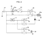
- Fig. 2 is a figure showing a control circuit for a solenoid portion of an electromagnetic valve shown in Fig. 1.
- Fig. 1 is a hydraulic circuit diagram showing essential portions of the embodiment of the winch operating device of the present invention, and in this figure the reference numeral 1 denotes a hydraulic pump for the main circuit, while 2 is a hydraulic pump for the operation system.
- the pressurized hydraulic fluid output from the hydraulic pump 2 is conducted to the one sides of a pair of pressure reducing valves 3a and 3b which are operated by a control lever 3.
- control lever 3 When the control lever 3 is operated so as to be tilted from its neutral position towards the right or the left as shown in the figure, then in correspondence to the amount of this operation the pilot pressure which is output from the one or the other of the pressure reducing valves 3a and 3b is increased, and thereby the spool element of the control valve 4 is shifted from its neutral position to the right or to the left. Due to this, the hydraulic pressure from the hydraulic pump 1 is supplied to the hydraulic motor 5, so that this hydraulic motor 5 is driven.
- a clutch cylinder 7 is provided for controlling a clutch for interrupting the rotational force transmission path from the hydraulic motor 5 to the winch drum 6.
- the reference numeral 10 denotes a brake mechanism for braking the winch drum 6.
- This brake mechanism 10 comprises a brake pedal 11, a brake cylinder 12, a brake band 13 which is provided as being wound around the external circumference of the winch drum 6, a link 14 which links together the operation of the brake cylinder 12 and of the brake band 13, and a pressure reduction valve 15.
- the brake cylinder 12 is operated according to the magnitude of a brake release hydraulic pressure which is supplied to it via the pressure reduction valve 15. When the brake release pressure increases, the brake cylinder 12 is driven in its direction to oppose the resistance of a spring 12a, and in linked operation therewith the brake band 13 is loosened and releases its braking of the winch drum 6.
- a manual switchover valve 20 In order to control these hydraulic pressures which are supplied to the above described clutch cylinder 7 and brake mechanism 10 there are provided, in the hydraulic circuit of this embodiment of the present invention, a manual switchover valve 20, a pair of hydraulic pressure pilot type switchover valves 21 and 22, and an electromagnetic valve 23.
- the manual switchover valve 20 is switched between positions denoted by “a” and “b” in the figure by the operation of a lever 20a which is provided in the driving chamber of the construction machine to which this device is provided.
- the position "a” is a position for preventing so called free fall of the winch drum 6, while the position "b” is a position which allows such free fall.
- the switchover valve 21 controls the clutch release hydraulic pressure which is supplied to the clutch cylinder 7, while the switchover valve 22 controls the brake release hydraulic pressure which is supplied from the hydraulic conduit 151 to the brake mechanism 10.
- the pilot pressure which is output from the pressure reducing valve 3a or the pressure reducing valve 3b increases, this pilot pressure is also supplied to the switchover valves 21 and 22 via a shuttle valve 8, and switches over the positions of these switchover valves 21 and 22 to positions designated by "b".
- the switchover valves 21 and 22 are maintained at their positions designated by "a" in the figure.
- the electromagnetic valve 23 is switched over to its position designated by "b" in the figure when a solenoid portion 23a thereof is supplied with actuating electrical energy so as to be magnetically energized by a control circuit which will be described hereinafter, while it is switched over to its position designated by “a” in the figure when this solenoid portion 23a is not so energized.
- a pressure switch 31 is provided to a hydraulic conduit 210 which leads from the electromagnetic valve 23 to the switchover valve 21, and is turned on when the pressure supplied to it reaches a predetermined value.
- the reference numeral 32 denotes a push button switch which is operated when free fall is to be performed, while 33 denotes a warning light which is provided in the driving chamber in order to warn the operator of the state in which free fall is possible.
- Fig. 2 is a figure showing the control circuit for the solenoid portion 23a of the electromagnetic valve 23.
- a relay 34 is energized and the solenoid portion 23a is energized.
- the pressure switch 31 is turned on, relays 35 and 36 are energized, and along with energizing the solenoid portion 23a the warning light 33 is turned on.
- the reference numeral 37 denotes a power source, while 38 denotes a diode.
- the push button switch 32 comprises a push button 32a, contact points 32b which are turned on (connected together) in response to the pressing of this push button 32a, and a spring 32c which biases the push button 32a in its direction to turn off (disconnect from one another) the contact points 32b. Accordingly, this push button switch 32 is constructed as a so called automatic return type switch.
- the manual switchover valve 20 is manually switched to its "a" position.
- the output hydraulic pressure from the hydraulic pump 2 is blocked by this manual switchover valve 20, and thus hydraulic pressure is prevented from being supplied via the manual switchover valve 20 to the switchover valve 22 and the electromagnetic valve 23.
- the clutch cylinder 7 is communicated to the tank 1, and accordingly the clutch is on, i.e. the hydraulic motor 5 and the winch drum 6 remain connected together, without any dependence upon the operational state of the control lever 3.
- the manual switchover valve 20 is manually switched to its "b" position, and the control lever 3 is kept in its neutral position.
- the output hydraulic pressure from the hydraulic pump 2 is conducted via this manual switchover valve 20 to the primary sides of the switchover valve 22 and of the electromagnetic valve 23, and also, since the switchover valve 22 is maintained in its "a" position, the output hydraulic pressure from the hydraulic pump 2 is conducted via the hydraulic conduit 151 to the pressure reduction valve 15.
- the brake pedal 11 is stepped upon, the hydraulic pressure in the hydraulic conduit 151 is blocked by the pressure reduction valve 15, and the brake release hydraulic pressure for operating the brake cylinder 12 is released to the tank 16 via the hydraulic conduit 152.
- the winch drum 6 remains braked by the brake cylinder 12.
- the brake pedal 11 is released, the hydraulic pressure in the hydraulic conduit 151 is conducted via the pressure reduction valve 15 to the brake cylinder 12, and braking of the winch drum 6 is released. That is to say, braking operation with the negative braking function becomes impossible in this state.
- switchover valve 20 is not to be considered as being limited to the case of a manually operated valve. It would also be possible to apply the present invention to the case in which the engagement and disengagement of the clutch were performed by some control member other than the one by which switching over of the brake mode was performed.
Landscapes
- Engineering & Computer Science (AREA)
- Mechanical Engineering (AREA)
- Control And Safety Of Cranes (AREA)
- Braking Arrangements (AREA)
- Mechanical Control Devices (AREA)
Applications Claiming Priority (2)
| Application Number | Priority Date | Filing Date | Title |
|---|---|---|---|
| JP7150381A JPH092785A (ja) | 1995-06-16 | 1995-06-16 | ウインチの操作装置 |
| JP150381/95 | 1995-06-16 |
Publications (2)
| Publication Number | Publication Date |
|---|---|
| EP0748760A2 true EP0748760A2 (de) | 1996-12-18 |
| EP0748760A3 EP0748760A3 (de) | 1998-03-04 |
Family
ID=15495761
Family Applications (1)
| Application Number | Title | Priority Date | Filing Date |
|---|---|---|---|
| EP96201673A Withdrawn EP0748760A3 (de) | 1995-06-16 | 1996-06-14 | Bedienungsvorrichtung für eine Winde |
Country Status (3)
| Country | Link |
|---|---|
| EP (1) | EP0748760A3 (de) |
| JP (1) | JPH092785A (de) |
| KR (1) | KR100191674B1 (de) |
Cited By (2)
| Publication number | Priority date | Publication date | Assignee | Title |
|---|---|---|---|---|
| WO2007129335A1 (en) * | 2006-05-09 | 2007-11-15 | Navalimpianti S.P.A. | Auto-controlled winch for handling loads on ships, crafts, boats, pontoons, platforms and similar in particular for lifeboats or other loads |
| WO2019093970A1 (en) * | 2017-11-10 | 2019-05-16 | Tajfun Planina Proizvodnja Strojev D.O.O. | Hydraulic assembly for controlling a winding drum by means of a brake and clutch in a forestry winch |
Families Citing this family (1)
| Publication number | Priority date | Publication date | Assignee | Title |
|---|---|---|---|---|
| JP6645937B2 (ja) * | 2016-09-13 | 2020-02-14 | 住友重機械建機クレーン株式会社 | ウインチのブレーキ装置 |
Family Cites Families (6)
| Publication number | Priority date | Publication date | Assignee | Title |
|---|---|---|---|---|
| JPS6052077B2 (ja) * | 1977-11-28 | 1985-11-16 | 日立建機株式会社 | 油圧ウインチにおける吊り荷の落下防止装置 |
| JPS56165696A (en) * | 1980-05-26 | 1981-12-19 | Komatsu Mfg Co Ltd | Brake gear for oil pressure type crane winch |
| US4398698A (en) * | 1981-05-29 | 1983-08-16 | Fmc Corporation | Freefall winch system and method of operation |
| US4549640A (en) * | 1982-01-28 | 1985-10-29 | Hitachi Construction Machinery Co., Ltd. | Operation system for hoisting device |
| JPH01145997A (ja) * | 1987-11-30 | 1989-06-07 | Kobe Steel Ltd | 油圧駆動ウインチの操作装置 |
| JP3251651B2 (ja) * | 1992-08-14 | 2002-01-28 | 日立建機株式会社 | ウインチの制御装置 |
-
1995
- 1995-06-16 JP JP7150381A patent/JPH092785A/ja active Pending
-
1996
- 1996-06-14 KR KR1019960021383A patent/KR100191674B1/ko not_active Expired - Fee Related
- 1996-06-14 EP EP96201673A patent/EP0748760A3/de not_active Withdrawn
Cited By (2)
| Publication number | Priority date | Publication date | Assignee | Title |
|---|---|---|---|---|
| WO2007129335A1 (en) * | 2006-05-09 | 2007-11-15 | Navalimpianti S.P.A. | Auto-controlled winch for handling loads on ships, crafts, boats, pontoons, platforms and similar in particular for lifeboats or other loads |
| WO2019093970A1 (en) * | 2017-11-10 | 2019-05-16 | Tajfun Planina Proizvodnja Strojev D.O.O. | Hydraulic assembly for controlling a winding drum by means of a brake and clutch in a forestry winch |
Also Published As
| Publication number | Publication date |
|---|---|
| KR970001203A (ko) | 1997-01-21 |
| KR100191674B1 (ko) | 1999-06-15 |
| EP0748760A3 (de) | 1998-03-04 |
| JPH092785A (ja) | 1997-01-07 |
Similar Documents
| Publication | Publication Date | Title |
|---|---|---|
| KR101155718B1 (ko) | 굴삭기의 주행제어장치 | |
| CA1162963A (en) | Vehicle brake system | |
| JPH09184169A (ja) | ホイールタイプ掘削機の作業ブレーキ装置 | |
| CA1077090A (en) | Vehicle brake control system | |
| US5484352A (en) | Switch for detecting operation of control valve spool | |
| US4549640A (en) | Operation system for hoisting device | |
| KR100191674B1 (ko) | 윈치의 조작장치 | |
| JP3635333B2 (ja) | 車両用オートクラッチ装置 | |
| JP2529513Y2 (ja) | クレーンの巻胴制御装置 | |
| JPH10291432A (ja) | トルクコンバータ車の制動装置 | |
| JPH0130476Y2 (de) | ||
| JPS6056795A (ja) | 巻胴の油圧制御装置 | |
| JPS6220732Y2 (de) | ||
| JP2960825B2 (ja) | 作業車両のパーキングブレーキ装置 | |
| JPH0126714Y2 (de) | ||
| JPH0529834U (ja) | 作業車両の動力取出装置 | |
| JP2616834B2 (ja) | 荷役車両 | |
| KR100189460B1 (ko) | 차량의 스타트보조장치 | |
| JPH0218068Y2 (de) | ||
| JPH0492122A (ja) | 荷役車両 | |
| JPH0358999B2 (de) | ||
| JPS6114694Y2 (de) | ||
| JPH0439256Y2 (de) | ||
| JPS58130894A (ja) | 巻上ウインチの操作装置 | |
| JPH1143294A (ja) | 2ドラムウインチのクラッチ・ブレーキ制御装置 |
Legal Events
| Date | Code | Title | Description |
|---|---|---|---|
| PUAI | Public reference made under article 153(3) epc to a published international application that has entered the european phase |
Free format text: ORIGINAL CODE: 0009012 |
|
| AK | Designated contracting states |
Kind code of ref document: A2 Designated state(s): DE FR NL |
|
| PUAL | Search report despatched |
Free format text: ORIGINAL CODE: 0009013 |
|
| AK | Designated contracting states |
Kind code of ref document: A3 Designated state(s): DE FR NL |
|
| 17P | Request for examination filed |
Effective date: 19980408 |
|
| 17Q | First examination report despatched |
Effective date: 20000302 |
|
| GRAH | Despatch of communication of intention to grant a patent |
Free format text: ORIGINAL CODE: EPIDOS IGRA |
|
| STAA | Information on the status of an ep patent application or granted ep patent |
Free format text: STATUS: THE APPLICATION IS DEEMED TO BE WITHDRAWN |
|
| 18D | Application deemed to be withdrawn |
Effective date: 20021231 |