EP0761309B1 - Pulvérisateur avec classificateur à haute performance - Google Patents
Pulvérisateur avec classificateur à haute performance Download PDFInfo
- Publication number
- EP0761309B1 EP0761309B1 EP95309159A EP95309159A EP0761309B1 EP 0761309 B1 EP0761309 B1 EP 0761309B1 EP 95309159 A EP95309159 A EP 95309159A EP 95309159 A EP95309159 A EP 95309159A EP 0761309 B1 EP0761309 B1 EP 0761309B1
- Authority
- EP
- European Patent Office
- Prior art keywords
- mill
- accordance
- classifier
- pulverizer
- vanes
- Prior art date
- Legal status (The legal status is an assumption and is not a legal conclusion. Google has not performed a legal analysis and makes no representation as to the accuracy of the status listed.)
- Expired - Lifetime
Links
Images


Classifications
-
- B—PERFORMING OPERATIONS; TRANSPORTING
- B02—CRUSHING, PULVERISING, OR DISINTEGRATING; PREPARATORY TREATMENT OF GRAIN FOR MILLING
- B02C—CRUSHING, PULVERISING, OR DISINTEGRATING IN GENERAL; MILLING GRAIN
- B02C15/00—Disintegrating by milling members in the form of rollers or balls co-operating with rings or discs
- B02C15/007—Mills with rollers pressed against a rotary horizontal disc
-
- B—PERFORMING OPERATIONS; TRANSPORTING
- B02—CRUSHING, PULVERISING, OR DISINTEGRATING; PREPARATORY TREATMENT OF GRAIN FOR MILLING
- B02C—CRUSHING, PULVERISING, OR DISINTEGRATING IN GENERAL; MILLING GRAIN
- B02C23/00—Auxiliary methods or auxiliary devices or accessories specially adapted for crushing or disintegrating not provided for in preceding groups or not specially adapted to apparatus covered by a single preceding group
- B02C23/08—Separating or sorting of material, associated with crushing or disintegrating
- B02C23/16—Separating or sorting of material, associated with crushing or disintegrating with separator defining termination of crushing or disintegrating zone, e.g. screen denying egress of oversize material
-
- B—PERFORMING OPERATIONS; TRANSPORTING
- B02—CRUSHING, PULVERISING, OR DISINTEGRATING; PREPARATORY TREATMENT OF GRAIN FOR MILLING
- B02C—CRUSHING, PULVERISING, OR DISINTEGRATING IN GENERAL; MILLING GRAIN
- B02C23/00—Auxiliary methods or auxiliary devices or accessories specially adapted for crushing or disintegrating not provided for in preceding groups or not specially adapted to apparatus covered by a single preceding group
- B02C23/18—Adding fluid, other than for crushing or disintegrating by fluid energy
- B02C23/24—Passing gas through crushing or disintegrating zone
- B02C23/32—Passing gas through crushing or disintegrating zone with return of oversize material to crushing or disintegrating zone
-
- B—PERFORMING OPERATIONS; TRANSPORTING
- B07—SEPARATING SOLIDS FROM SOLIDS; SORTING
- B07B—SEPARATING SOLIDS FROM SOLIDS BY SIEVING, SCREENING, SIFTING OR BY USING GAS CURRENTS; SEPARATING BY OTHER DRY METHODS APPLICABLE TO BULK MATERIAL, e.g. LOOSE ARTICLES FIT TO BE HANDLED LIKE BULK MATERIAL
- B07B11/00—Arrangement of accessories in apparatus for separating solids from solids using gas currents
-
- B—PERFORMING OPERATIONS; TRANSPORTING
- B07—SEPARATING SOLIDS FROM SOLIDS; SORTING
- B07B—SEPARATING SOLIDS FROM SOLIDS BY SIEVING, SCREENING, SIFTING OR BY USING GAS CURRENTS; SEPARATING BY OTHER DRY METHODS APPLICABLE TO BULK MATERIAL, e.g. LOOSE ARTICLES FIT TO BE HANDLED LIKE BULK MATERIAL
- B07B7/00—Selective separation of solid materials carried by, or dispersed in, gas currents
- B07B7/08—Selective separation of solid materials carried by, or dispersed in, gas currents using centrifugal force
- B07B7/086—Selective separation of solid materials carried by, or dispersed in, gas currents using centrifugal force generated by the winding course of the gas stream
-
- B—PERFORMING OPERATIONS; TRANSPORTING
- B02—CRUSHING, PULVERISING, OR DISINTEGRATING; PREPARATORY TREATMENT OF GRAIN FOR MILLING
- B02C—CRUSHING, PULVERISING, OR DISINTEGRATING IN GENERAL; MILLING GRAIN
- B02C15/00—Disintegrating by milling members in the form of rollers or balls co-operating with rings or discs
- B02C2015/002—Disintegrating by milling members in the form of rollers or balls co-operating with rings or discs combined with a classifier
Definitions
- This invention relates to pulverizer mills, e.g., mills that are used for the crushing of large pieces of coal into smaller coal particles. More particularly, this invention relates to a dust separating system known as a classifier which is designed to segregate large, partly ground coal particles from smaller, completely ground particles within a pulverizer mill.
- Pulverizer mills are commonly used for crushing large coal pieces into small particles which are required for conventional coal fired boilers.
- a common type of pulverizer mill includes a flat or dished grinding bowl or table which is attached to and driven by a vertical spindle and three (3) large rollers or wheels which rotate around separate shafts as the bowl rotates with the vertical spindle. Large coal particles are introduced onto the bowl and are crushed as they are captured between the rollers and the bowl.
- An air stream (known as primary air flow) passing upwardly around the bowl carries the crushed coal particles upward into the classifier through the classifier vanes and then out of the mill to the boiler through an outlet pipe or pipes.
- a pulverizer mill having a classifier with a plurality of fixed vanes attached to the upper end of the inner conical wall of the mill, for imparting a rotational motion to the air-solids stream, and at least three pivotable deflector vanes downstream thereof, at the top of the classifier.
- an improved classifier system for a pulverizer mill (e.g., a mill of the type used for crushing coal into fine particles).
- the improved classifier system is characterised by a cylindrical extension member (sometimes referred to herein as a finned cyclone classifier section) which is secured to and extends vertically upwardly from the upper end of the conical classifier.
- the extension member has an interior surface which includes a plurality of projections extending radially inward.
- the improved classifier system also includes an intermediate classification liner attached circumferentially to the interior surface of the mill housing high above the grinding elements (or grinding zone).
- the intermediate classification liner provides a converging-diverging orifice assembly which extends around the interior surface of the housing between the grinding zone and the classifier.
- This intermediate classification liner redirects the upwardly moving and turbulent primary air flow towards the center of the pulverizer mill. This redirection of the primary air flow will result in a large loss of upward momentum in the bigger partly ground coal particles, causing them to fall back into the grinding zone without passing through the classifier.
- This new method of particle separation is referred to herein as intermediate classification.
- the classifier system includes curved classifier vanes at the upper end (and inlet) of the classifier, and preferably (but not necessarily) the vanes extend downwardly to a point below the air inlet to the classifier.
- the curved vanes greatly enhance the spin of the air flow entering the upper end of the classifier, although larger flat vanes may also be used.
- Another improvement involves a plurality of vanes located on the interior surface of the pulverizer housing located immediately below the inlet to the upper end of the classifier or immediately below the lower end of the classifier vanes.
- This plurality of vanes being a new design feature not found in any prior art description, is referred to herein as a spin initiator.
- the plurality of vanes are located parallel to each other and are tilted at an angle in the range of about 30° to 45° relative to the vertical plane.
- the spin initiator effectively controls the upwardly flowing and turbulent primary air flow within the upper region of the mill housing.
- the spin initiator re-directs the air flow, causing a strong clockwise or counter-clockwise motion of the primary air flow, depending upon the specific mill design. This turning of the primary air flow greatly increases the efficiency of the classifier vanes.
- This outlet turret extension is located at the top of the existing pulverizer mill housing.
- This extension is positioned in such a manner so as to increase the overall height of the existing coal pulverizer mill. By increasing the overall height of said pulverizer mill, the volume is thus increased as well. This increase in volume will improve the efficiency of coal particle separation within the housing of the pulverizer mill.
- This outlet turret extension is normally cylindrically shaped (although other shapes may exist if the existing pulverizer mill housing so dictates), the length of which is determined for each individual coal pulverizer mill.
- coal particles which are carried out of the mill by the primary air flow, are much more finely ground when compared to prior art classifier designs.
- This system is as easy to retrofit as any conventional replacement static classifier and much less expensive than dynamic or rotating classifiers which are currently available. Also no additional power requirements are needed for auxiliary drive motors or other associated equipment which may be necessary with rotating classifiers.
- This system of the invention greatly reduces the amount of unburned (wasted) coal which ultimately must be purchased by the user of the pulverizer mill.
- a method of constructing a pulverizer mill as defined above as the first aspect of the invention comprising the step of retro-fitting a said extension member to a previously constructed mill not already having a said extension member.
- items such as the intermediate classification liner, spacer assembly, curved classifier vanes and spin initiator vanes are also required, they may likewise be retro-fitted.
- the high performance classification system all components of the said classification system are constructed of a steel material, either mild steel or of a wear-resistant type. Further, said components may be protectively lined or covered with abrasion-resistant ceramic tiles of numerous descriptions. Also said components may be protectively lined or covered with welded overlays of high-alloy wear-resistant material.
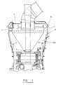
- the outlet turret extension 1 is located at the top of the existing pulverizer mill housing 10. This outlet turret extension acts as a volume-increasing device which may be located either at the top of or at the bottom of any existing coal pulverizer mill housing. The specific design of the coal pulverizer mill will dictate the location and installation method of the outlet turret extension.
- outlet turret extension will be constructed with a cross-sectional shape which corresponds to the existing pulverizer mill housing. This shape may be cylindrical, hexagonal, or any other shape utilized by coal pulverizer manufacturers. Note that the outlet turret extension is also shown in Fig. 3.
- the spin initiator comprises a plurality of evenly-spaced vanes, which are oriented at 30° to 45° to the vertical.
- the spin initiator vanes are normally welded to the interior surface of the coal pulverizer mill housing.
- the spin initiator vanes may be combined with and secured to the outlet turret extension. This will minimise the installation difficulties and costs for the end user of the coal pulverizer mill.
- both drawings depict the spin initiator and the outlet turret extension as an integral unit these devices may, in fact, be installed as separate units in the high performance classification system.
- Fig. 1 also depicts the intermediate deflector liner 3.
- the intermediate deflector liner is a circumferentially-built converging-diverging orifice assembly. Also constructed of a steel material as described above, this liner assembly may be bolted or welded to the interior surface 10A of the existing pulverizer mill housing. As dictated by the individual pulverizer mill design, the intermediate deflector liner will be constructed with upwardly and downwardly sloping surfaces which are oriented at 30° to 60° to the horizontal plane. Thus, the total developed angle between the two sloping surfaces would be in the range 60° to 120°.
- the components of the intermediate deflector liner may be designed and built as a single unit or may be designed as separate smaller segments for easier installation.
- cesta-curved classifier vanes 4 Another feature of the high performance classification system shown in Fig. 1 are the cesta-curved classifier vanes 4.
- the cesta-curved classifier vanes feature is one of the preferred aspects of this design and will increase the efficiency of the coal particle separation in the top region of the interior of the classifier cone.
- flat or planar classifier vanes may be utilized with only a slight degradation of the high performance classification system's performance.
- the flat classifier vanes will reduce costs and are easier to construct from a wear-resistant material.
- the cesta-curve of the classifier vanes is unique to this high performance classification system. Note that this classifier vane design is also shown in Fig. 4.
- the finned cyclone classifier section 5 is also shown in Fig. 1.
- a detailed view of one embodiment of this extension member is shown in Fig. 2.
- the interior surface of this section of the classifier is rough by design. It may be thought of as being similar to the corrugations found in certain types of cardboard construction.
- This roughened surface area which consists of a plurality of spaced and radially inward projecting structures 5A, may have a variety of different designs.
- the details shown in Fig. 2 represent a piece of steel sheet which has been folded and bent into the shape drawn. Other construction methods may include the welding or fastening of steel bars, which in themselves may be of a variety of shapes, to the inside surface of a cylindrical body.
- the high performance classifier system may include a classifier cone outlet extension, as is known in the art.
- This outlet extension is useful in the control of partly ground coal particles, in that these partly ground particles may be more accurately returned to the grinding zone of the pulverizer.
- This outlet extension may normally be constructed from a mild or wear-resistant steel material. This outlet extension will, in many cases, enhance the control of the coal fineness by increasing the efficiency of the crushing of the already partly-ground coal particles.
- the cone outlet may also include an adjustable restriction ring 7 which may be used to control the primary air flow in such a way that this air will not flow into the lower end of the cone or upwardly through the interior of the high performance classifier, thus reducing the efficiency of the system.
- the ring 7 defines an annular opening at the lower end of the cone.
Landscapes
- Engineering & Computer Science (AREA)
- Food Science & Technology (AREA)
- Combined Means For Separation Of Solids (AREA)
- Crushing And Grinding (AREA)
- Disintegrating Or Milling (AREA)
Claims (23)
- Installation de pulvérisation comprenant un moyen de pulvérisation pour broyer du charbon, un conduit d'alimentation vertical pour introduire du charbon dans ledit moyen de pulvérisation, un classificateur en forme de cône pour séparer de grosses particules de petites particules, et un moyen pour faire circuler de l'air vers le haut depuis ledit moyen de pulvérisation jusqu'audit classificateur, dans laquelle ledit classificateur comprend des extrémités supérieure et inférieure, et qui est caractérisée en ce qu'un élément d'extension cylindrique (5) est fixé à ladite extrémité supérieure dudit classificateur et s'étend verticalement vers le haut à partir de celle-ci, ledit élément d'extension comprenant une surface intérieure, laquelle comprend plusieurs saillies (5A) s'étendant radialement vers l'intérieur.
- Installation de pulvérisation selon la revendication 1, dans laquelle lesdites saillies comprennent des nervures parallèles (5A).
- Installation de pulvérisation selon l'une des revendications précédentes, dans laquelle ladite installation comprend un carter (10) ayant une surface intérieure (10A), et comprend en outre une chemise de classification intermédiaire (3) fixée à ladite surface intérieure dudit carter, ladite chemise de classification intermédiaire définissant un orifice convergent-divergent.
- Installation de pulvérisation selon la revendication 3, dans laquelle ladite chemise de classification intermédiaire s'étend autour de la surface intérieure dudit carter, au-dessus dudit moyen de broyage et au-dessous de l'entrée dans ledit classificateur.
- Installation de pulvérisation selon la revendication 3 ou 4, dans laquelle ladite chemise de classification s'étend vers l'intérieur à partir de ladite surface intérieure, sur une distance située dans la plage d'environ 4 à 12 pouces (10,2 à 30,5 cm).
- Installation de pulvérisation selon la revendication 5, dans laquelle ledit orifice comprend une surface en pente descendante et une surface en pente ascendante, dans laquelle l'angle desdites surfaces en pente est dans la plage d'environ 30° à 60°, l'angle développé entre les deux surfaces en pente étant dans la plage située entre 60° à 120°.
- Installation de pulvérisation selon l'une quelconque des revendications précédentes, comprenant en outre des ailettes de classificateur incurvées (4) au niveau de l'extrémité supérieure dudit classificateur, au niveau de l'entrée dans ledit classificateur.
- Installation de pulvérisation selon la revendication 7, dans laquelle ledit classificateur comprend une entrée, et dans laquelle lesdites ailettes de classificateur s'étendent vers le bas jusqu'à un point situé au-dessous de ladite entrée.
- Installation de pulvérisation selon l'une quelconque des revendications précédentes, dans laquelle ladite installation comprend un carter, et comprend en outre des ailettes d'amorçage de rotation (2) disposées entre ledit carter et ladite extrémité supérieure dudit classificateur.
- Installation de pulvérisation selon la revendication 9, dans laquelle les ailettes d'amorçage de rotation sont parallèles les unes aux autres et orientées selon un angle situé dans la plage d'environ 30° à 45° par rapport à un plan vertical.
- Installation de pulvérisation selon la revendication 9 ou 10, dans laquelle les ailettes d'amorçage de rotation sont régulièrement espacées et orientées selon un angle situé dans la plage de 30° à 45° par rapport à un plan vertical.
- Installation de pulvérisation selon la revendication 9, 10 ou 11, dans laquelle les ailettes d'amorçage de rotation sont situées immédiatement au-dessous de l'entrée dans l'extrémité supérieure du classificateur.
- Installation de pulvérisation selon l'une quelconque des revendications 9 à 12 en association avec l'une des revendications 7 et 8, dans laquelle les ailettes d'amorçage de rotation sont situées immédiatement au-dessous de l'extrémité inférieure des ailettes du classificateur.
- Installation de pulvérisation selon l'une quelconque des revendications 9 à 13, dans laquelle les ailettes d'amorçage de rotation sont soudées sur la surface intérieure du carter.
- Installation de pulvérisation selon l'une quelconque des revendications précédentes, dans laquelle ladite installation comprend un carter, et comprend en outre un ensemble intercalaire d'augmentation de volume situé au niveau de la partie supérieure ou de la partie inférieure dudit carter.
- Installation de pulvérisation selon la revendication 15, dans laquelle l'ensemble intercalaire est situé au niveau de la partie supérieure dudit carter.
- Installation de pulvérisation selon la revendication 16, dans laquelle la forme en coupe transversale de l'ensemble intercalaire correspond à celle du carter de l'installation.
- Installation de pulvérisation selon la revendication 17, dans laquelle l'ensemble intercalaire est cylindrique.
- Installation de pulvérisation selon l'une quelconque des revendications 16 à 18, dans laquelle l'ensemble intercalaire est soudé sur la partie supérieure du carter de l'installation.
- Installation de pulvérisation selon l'une quelconque des revendications 16 à 18, dans laquelle l'ensemble intercalaire est monté sur la partie supérieure du carter de l'installation, au moyen de boulons fixés par l'intermédiaire de brides.
- Installation de pulvérisation selon l'une quelconque des revendications 15 à 20, en association avec l'une quelconque des revendications 9 à 13, dans laquelle les ailettes d'amorçage de rotation sont portées par l'ensemble intercalaire.
- Procédé de construction d'une installation de pulvérisation selon l'une quelconque des revendications précédentes, comprenant l'étape de montage après coup dudit élément d'extension sur une installation construite antérieurement non encore équipée d'un tel élément d'extension.
- Procédé selon la revendication 22, comprenant la ou les étape(s) supplémentaire(s) de montage après coup d'une chemise de classification intermédiaire selon l'une des revendications 3 à 6 et/ou d'ailettes de classificateur incurvées selon l'une des revendications 7 et 8 et/ou d'ailettes d'amorçage de rotation selon l'une des revendications 9 à 14, et/ou d'un ensemble intercalaire selon l'une des revendications 15 à 21, sur ladite installation construite antérieurement.
Priority Applications (2)
| Application Number | Priority Date | Filing Date | Title |
|---|---|---|---|
| EP97114161A EP0804964B1 (fr) | 1995-09-06 | 1995-12-15 | Pulvérisateur avec classificateur à haute performance |
| EP97114162A EP0812623B1 (fr) | 1995-09-06 | 1995-12-15 | Pulvérisateur avec classificateur à haute performance |
Applications Claiming Priority (3)
| Application Number | Priority Date | Filing Date | Title |
|---|---|---|---|
| US08/524,246 US5605292A (en) | 1995-09-06 | 1995-09-06 | Pulverizer mill high performance classifier system |
| US524246 | 1995-09-06 | ||
| CA002191172A CA2191172C (fr) | 1995-09-06 | 1996-11-25 | Systeme de classification haute performance pour broyeur pulverisateur |
Related Child Applications (2)
| Application Number | Title | Priority Date | Filing Date |
|---|---|---|---|
| EP97114161A Division EP0804964B1 (fr) | 1995-09-06 | 1995-12-15 | Pulvérisateur avec classificateur à haute performance |
| EP97114162A Division EP0812623B1 (fr) | 1995-09-06 | 1995-12-15 | Pulvérisateur avec classificateur à haute performance |
Publications (2)
| Publication Number | Publication Date |
|---|---|
| EP0761309A1 EP0761309A1 (fr) | 1997-03-12 |
| EP0761309B1 true EP0761309B1 (fr) | 1999-03-31 |
Family
ID=25678853
Family Applications (3)
| Application Number | Title | Priority Date | Filing Date |
|---|---|---|---|
| EP97114162A Expired - Lifetime EP0812623B1 (fr) | 1995-09-06 | 1995-12-15 | Pulvérisateur avec classificateur à haute performance |
| EP97114161A Expired - Lifetime EP0804964B1 (fr) | 1995-09-06 | 1995-12-15 | Pulvérisateur avec classificateur à haute performance |
| EP95309159A Expired - Lifetime EP0761309B1 (fr) | 1995-09-06 | 1995-12-15 | Pulvérisateur avec classificateur à haute performance |
Family Applications Before (2)
| Application Number | Title | Priority Date | Filing Date |
|---|---|---|---|
| EP97114162A Expired - Lifetime EP0812623B1 (fr) | 1995-09-06 | 1995-12-15 | Pulvérisateur avec classificateur à haute performance |
| EP97114161A Expired - Lifetime EP0804964B1 (fr) | 1995-09-06 | 1995-12-15 | Pulvérisateur avec classificateur à haute performance |
Country Status (9)
| Country | Link |
|---|---|
| US (1) | US5605292A (fr) |
| EP (3) | EP0812623B1 (fr) |
| AU (1) | AU694887B2 (fr) |
| CA (1) | CA2191172C (fr) |
| DE (3) | DE69515523T2 (fr) |
| DK (1) | DK0761309T3 (fr) |
| ES (3) | ES2146055T3 (fr) |
| GB (1) | GB2295104B (fr) |
| ZA (1) | ZA966938B (fr) |
Families Citing this family (11)
| Publication number | Priority date | Publication date | Assignee | Title |
|---|---|---|---|---|
| DE19844112A1 (de) * | 1998-09-25 | 2000-03-30 | Loesche Gmbh | Schaufelkranz für Luftstrom-Wälzmühlen |
| RU2169616C2 (ru) * | 1999-04-07 | 2001-06-27 | Злобин Михаил Николаевич | Конусная дробилка |
| KR100740687B1 (ko) * | 2001-02-28 | 2007-07-18 | 박종현 | 분쇄기 |
| US6902126B2 (en) * | 2002-11-04 | 2005-06-07 | Alstom Technology Ltd | Hybrid turbine classifier |
| US20060118673A1 (en) * | 2004-11-22 | 2006-06-08 | Wark Rickey E | Method and apparatus for protected coal mill journals |
| US8945254B2 (en) * | 2011-12-21 | 2015-02-03 | General Electric Company | Gas turbine engine particle separator |
| US9211547B2 (en) | 2013-01-24 | 2015-12-15 | Lp Amina Llc | Classifier |
| US10722898B2 (en) | 2013-11-01 | 2020-07-28 | Mitsubishi Hitachi Power Systems, Ltd. | Vertical roller mill |
| GB2523295A (en) | 2013-12-02 | 2015-08-26 | Milling Plant Solutions Ltd | Pulveriser mills |
| JP6675003B2 (ja) * | 2015-11-19 | 2020-04-01 | ロエシェ ゲーエムベーハー | ミリングボウル |
| US10744534B2 (en) | 2016-12-02 | 2020-08-18 | General Electric Technology Gmbh | Classifier and method for separating particles |
Family Cites Families (15)
| Publication number | Priority date | Publication date | Assignee | Title |
|---|---|---|---|---|
| US1478478A (en) * | 1921-05-25 | 1923-12-25 | Otto A Kreutzberg | Pulverizing apparatus |
| DE503547C (de) * | 1928-05-11 | 1931-10-20 | Peters Ag Claudius | Vorrichtung zum Trennen der spezifisch leichteren Bestandteile von den spezifisch schwereren eines Gemisches in Muehlen |
| DE887929C (de) * | 1951-12-25 | 1953-08-27 | Kastrup K G Vorm Paul Pollrich | Fliehkraftabscheider zum kontinuierlichen Abscheiden von Baumwolle-, Zellwolle- od. dgl. Fasern |
| GB828515A (en) * | 1957-03-06 | 1960-02-17 | Babcock & Wilcox Ltd | Improvements in or relating to pulverisers |
| US2944744A (en) * | 1957-08-02 | 1960-07-12 | Berz Max | Ring and roller pulverizing apparatus |
| US3044714A (en) * | 1958-11-26 | 1962-07-17 | Babcock & Wilcox Ltd | Ball race pulverizer |
| NL110729C (fr) * | 1961-05-11 | |||
| US4597537A (en) * | 1982-09-14 | 1986-07-01 | Onoda Cement Company, Ltd. | Vertical mill |
| US4605174A (en) * | 1982-12-08 | 1986-08-12 | Combustion Engineering, Inc. | Vane wheel arrangement with nihard wear plates |
| US4523721A (en) * | 1982-12-08 | 1985-06-18 | Combustion Engineering, Inc. | Bowl mill with primary classifier assembly |
| US4504018A (en) * | 1982-12-13 | 1985-03-12 | Foster Wheeler Energy Corporation | Particle classifier apparatus and method with rudder control vane |
| GB2176134A (en) * | 1985-06-03 | 1986-12-17 | Smidth & Co As F L | Separator for sorting particulate material |
| CA1311232C (fr) * | 1989-07-20 | 1992-12-08 | Randall J. Novotny | Pulverisateur a table de broyage rotative avec segments d'arrivee d'air remplacables |
| JPH0655088A (ja) * | 1992-08-04 | 1994-03-01 | Mitsubishi Heavy Ind Ltd | 竪型ローラミル |
| JP3060398B2 (ja) * | 1994-08-08 | 2000-07-10 | ホソカワミクロン株式会社 | 微粉砕装置 |
-
1995
- 1995-09-06 US US08/524,246 patent/US5605292A/en not_active Expired - Lifetime
- 1995-12-14 GB GB9525554A patent/GB2295104B/en not_active Expired - Lifetime
- 1995-12-15 EP EP97114162A patent/EP0812623B1/fr not_active Expired - Lifetime
- 1995-12-15 DK DK95309159T patent/DK0761309T3/da active
- 1995-12-15 DE DE69515523T patent/DE69515523T2/de not_active Expired - Lifetime
- 1995-12-15 EP EP97114161A patent/EP0804964B1/fr not_active Expired - Lifetime
- 1995-12-15 ES ES97114161T patent/ES2146055T3/es not_active Expired - Lifetime
- 1995-12-15 ES ES97114162T patent/ES2141564T3/es not_active Expired - Lifetime
- 1995-12-15 DE DE69513199T patent/DE69513199T2/de not_active Expired - Lifetime
- 1995-12-15 ES ES95309159T patent/ES2132545T3/es not_active Expired - Lifetime
- 1995-12-15 DE DE69508751T patent/DE69508751T2/de not_active Expired - Lifetime
- 1995-12-15 EP EP95309159A patent/EP0761309B1/fr not_active Expired - Lifetime
-
1996
- 1996-08-15 ZA ZA9606938A patent/ZA966938B/xx unknown
- 1996-09-09 AU AU65533/96A patent/AU694887B2/en not_active Expired
- 1996-11-25 CA CA002191172A patent/CA2191172C/fr not_active Expired - Lifetime
Also Published As
| Publication number | Publication date |
|---|---|
| EP0804964A3 (fr) | 1997-12-10 |
| EP0812623B1 (fr) | 1999-11-03 |
| GB2295104B (en) | 1996-10-23 |
| GB9525554D0 (en) | 1996-02-14 |
| AU6553396A (en) | 1997-03-13 |
| AU694887B2 (en) | 1998-07-30 |
| ES2141564T3 (es) | 2000-03-16 |
| DE69513199D1 (de) | 1999-12-09 |
| ZA966938B (en) | 1997-02-19 |
| CA2191172C (fr) | 1999-01-19 |
| DE69508751T2 (de) | 1999-09-30 |
| EP0812623A1 (fr) | 1997-12-17 |
| DE69515523D1 (de) | 2000-04-13 |
| DE69513199T2 (de) | 2000-06-21 |
| US5605292A (en) | 1997-02-25 |
| CA2191172A1 (fr) | 1998-05-25 |
| ES2146055T3 (es) | 2000-07-16 |
| DK0761309T3 (da) | 1999-10-11 |
| GB2295104A (en) | 1996-05-22 |
| EP0804964B1 (fr) | 2000-03-08 |
| EP0761309A1 (fr) | 1997-03-12 |
| DE69508751D1 (de) | 1999-05-06 |
| ES2132545T3 (es) | 1999-08-16 |
| DE69515523T2 (de) | 2000-09-14 |
| EP0804964A2 (fr) | 1997-11-05 |
Similar Documents
| Publication | Publication Date | Title |
|---|---|---|
| CN1051943C (zh) | 粉磨机分级器 | |
| US4597537A (en) | Vertical mill | |
| US5957300A (en) | Classifier vane for coal mills | |
| EP0804964B1 (fr) | Pulvérisateur avec classificateur à haute performance | |
| EP0507983B1 (fr) | Pulvérisateur pourvu d'un anneau d'étranglement rotatif | |
| US4504018A (en) | Particle classifier apparatus and method with rudder control vane | |
| US7673827B2 (en) | Bowl mill for a coal pulverizer with an air mill for primary entry of air | |
| US5826807A (en) | Method and apparatus for comminuting of solid particles | |
| JPH06104204B2 (ja) | 垂直式ロ−ラミル | |
| WO2003015937A1 (fr) | Regulation de distribution d'un flux de particules entre les sorties d'un classificateur | |
| US8317119B2 (en) | Double course vane wheel | |
| EP0149221B1 (fr) | Trieur | |
| KR970006854Y1 (ko) | 분쇄기용 미분 분리장치 | |
| JP4759285B2 (ja) | 粉砕機 | |
| JP2523216Y2 (ja) | 粉体分級装置 | |
| JP2868099B2 (ja) | 竪型粉砕機 | |
| JPH0335993B2 (fr) | ||
| JPH0634826Y2 (ja) | 竪型ミル | |
| JP2740249B2 (ja) | 竪型ローラミル | |
| CA2243834C (fr) | Diffuseur ameliore de classificateur pour broyeurs de charbon | |
| CA2166941C (fr) | Systeme de controle de l'alimentation et de la granulometrie pour pulverisateur de charbon | |
| JPH067829Y2 (ja) | 空気分級機 | |
| CA2251514C (fr) | Aube amelioree pour classificateur de moulins a charbon | |
| JPH0257989B2 (fr) | ||
| JPH0636870B2 (ja) | ロ−ラミル |
Legal Events
| Date | Code | Title | Description |
|---|---|---|---|
| PUAI | Public reference made under article 153(3) epc to a published international application that has entered the european phase |
Free format text: ORIGINAL CODE: 0009012 |
|
| 17P | Request for examination filed |
Effective date: 19961003 |
|
| AK | Designated contracting states |
Kind code of ref document: A1 Designated state(s): BE DE DK ES FR IT NL PT SE |
|
| GRAG | Despatch of communication of intention to grant |
Free format text: ORIGINAL CODE: EPIDOS AGRA |
|
| GRAG | Despatch of communication of intention to grant |
Free format text: ORIGINAL CODE: EPIDOS AGRA |
|
| GRAG | Despatch of communication of intention to grant |
Free format text: ORIGINAL CODE: EPIDOS AGRA |
|
| GRAH | Despatch of communication of intention to grant a patent |
Free format text: ORIGINAL CODE: EPIDOS IGRA |
|
| GRAH | Despatch of communication of intention to grant a patent |
Free format text: ORIGINAL CODE: EPIDOS IGRA |
|
| DX | Miscellaneous (deleted) | ||
| GRAA | (expected) grant |
Free format text: ORIGINAL CODE: 0009210 |
|
| AK | Designated contracting states |
Kind code of ref document: B1 Designated state(s): BE DE DK ES FR IT NL PT SE |
|
| PG25 | Lapsed in a contracting state [announced via postgrant information from national office to epo] |
Ref country code: SE Free format text: THE PATENT HAS BEEN ANNULLED BY A DECISION OF A NATIONAL AUTHORITY Effective date: 19990331 Ref country code: NL Free format text: LAPSE BECAUSE OF FAILURE TO SUBMIT A TRANSLATION OF THE DESCRIPTION OR TO PAY THE FEE WITHIN THE PRESCRIBED TIME-LIMIT Effective date: 19990331 |
|
| REF | Corresponds to: |
Ref document number: 69508751 Country of ref document: DE Date of ref document: 19990506 |
|
| ET | Fr: translation filed | ||
| REG | Reference to a national code |
Ref country code: ES Ref legal event code: FG2A Ref document number: 2132545 Country of ref document: ES Kind code of ref document: T3 |
|
| NLV1 | Nl: lapsed or annulled due to failure to fulfill the requirements of art. 29p and 29m of the patents act | ||
| REG | Reference to a national code |
Ref country code: PT Ref legal event code: SC4A Free format text: AVAILABILITY OF NATIONAL TRANSLATION Effective date: 19990628 |
|
| REG | Reference to a national code |
Ref country code: DK Ref legal event code: T3 |
|
| PLBE | No opposition filed within time limit |
Free format text: ORIGINAL CODE: 0009261 |
|
| STAA | Information on the status of an ep patent application or granted ep patent |
Free format text: STATUS: NO OPPOSITION FILED WITHIN TIME LIMIT |
|
| 26N | No opposition filed | ||
| PGFP | Annual fee paid to national office [announced via postgrant information from national office to epo] |
Ref country code: FR Payment date: 20041227 Year of fee payment: 10 |
|
| PGFP | Annual fee paid to national office [announced via postgrant information from national office to epo] |
Ref country code: ES Payment date: 20051212 Year of fee payment: 11 |
|
| PG25 | Lapsed in a contracting state [announced via postgrant information from national office to epo] |
Ref country code: FR Free format text: LAPSE BECAUSE OF NON-PAYMENT OF DUE FEES Effective date: 20060831 |
|
| REG | Reference to a national code |
Ref country code: FR Ref legal event code: ST Effective date: 20060831 |
|
| REG | Reference to a national code |
Ref country code: ES Ref legal event code: FD2A Effective date: 20061216 |
|
| PG25 | Lapsed in a contracting state [announced via postgrant information from national office to epo] |
Ref country code: ES Free format text: LAPSE BECAUSE OF NON-PAYMENT OF DUE FEES Effective date: 20061216 |
|
| PGFP | Annual fee paid to national office [announced via postgrant information from national office to epo] |
Ref country code: DK Payment date: 20101210 Year of fee payment: 16 |
|
| PGFP | Annual fee paid to national office [announced via postgrant information from national office to epo] |
Ref country code: PT Payment date: 20101214 Year of fee payment: 16 |
|
| PGFP | Annual fee paid to national office [announced via postgrant information from national office to epo] |
Ref country code: DE Payment date: 20101222 Year of fee payment: 16 |
|
| PGFP | Annual fee paid to national office [announced via postgrant information from national office to epo] |
Ref country code: BE Payment date: 20110124 Year of fee payment: 16 |
|
| REG | Reference to a national code |
Ref country code: PT Ref legal event code: MM4A Free format text: LAPSE DUE TO NON-PAYMENT OF FEES Effective date: 20120615 |
|
| BERE | Be: lapsed |
Owner name: *BUNTON JOE H. Effective date: 20111231 |
|
| REG | Reference to a national code |
Ref country code: DK Ref legal event code: EBP |
|
| PG25 | Lapsed in a contracting state [announced via postgrant information from national office to epo] |
Ref country code: PT Free format text: LAPSE BECAUSE OF NON-PAYMENT OF DUE FEES Effective date: 20120615 |
|
| REG | Reference to a national code |
Ref country code: DE Ref legal event code: R119 Ref document number: 69508751 Country of ref document: DE Effective date: 20120703 |
|
| PG25 | Lapsed in a contracting state [announced via postgrant information from national office to epo] |
Ref country code: BE Free format text: LAPSE BECAUSE OF NON-PAYMENT OF DUE FEES Effective date: 20111231 Ref country code: DE Free format text: LAPSE BECAUSE OF NON-PAYMENT OF DUE FEES Effective date: 20120703 |
|
| PG25 | Lapsed in a contracting state [announced via postgrant information from national office to epo] |
Ref country code: DK Free format text: LAPSE BECAUSE OF NON-PAYMENT OF DUE FEES Effective date: 20120102 |
|
| PGFP | Annual fee paid to national office [announced via postgrant information from national office to epo] |
Ref country code: IT Payment date: 20121221 Year of fee payment: 18 |
|
| PG25 | Lapsed in a contracting state [announced via postgrant information from national office to epo] |
Ref country code: IT Free format text: LAPSE BECAUSE OF NON-PAYMENT OF DUE FEES Effective date: 20131215 |