EP0762338A2 - Procédé pour sécuriser les données et le code de programme d'une machine d'affranchissement - Google Patents
Procédé pour sécuriser les données et le code de programme d'une machine d'affranchissement Download PDFInfo
- Publication number
- EP0762338A2 EP0762338A2 EP96250192A EP96250192A EP0762338A2 EP 0762338 A2 EP0762338 A2 EP 0762338A2 EP 96250192 A EP96250192 A EP 96250192A EP 96250192 A EP96250192 A EP 96250192A EP 0762338 A2 EP0762338 A2 EP 0762338A2
- Authority
- EP
- European Patent Office
- Prior art keywords
- data
- mac
- franking machine
- program
- routine
- Prior art date
- Legal status (The legal status is an assumption and is not a legal conclusion. Google has not performed a legal analysis and makes no representation as to the accuracy of the status listed.)
- Ceased
Links
Images


Classifications
-
- G—PHYSICS
- G07—CHECKING-DEVICES
- G07B—TICKET-ISSUING APPARATUS; FARE-REGISTERING APPARATUS; FRANKING APPARATUS
- G07B17/00—Franking apparatus
- G07B17/00733—Cryptography or similar special procedures in a franking system
-
- G—PHYSICS
- G07—CHECKING-DEVICES
- G07B—TICKET-ISSUING APPARATUS; FARE-REGISTERING APPARATUS; FRANKING APPARATUS
- G07B17/00—Franking apparatus
- G07B17/00733—Cryptography or similar special procedures in a franking system
- G07B2017/00741—Cryptography or similar special procedures in a franking system using specific cryptographic algorithms or functions
- G07B2017/00774—MAC (Message Authentication Code), e.g. DES-MAC
-
- G—PHYSICS
- G07—CHECKING-DEVICES
- G07B—TICKET-ISSUING APPARATUS; FARE-REGISTERING APPARATUS; FRANKING APPARATUS
- G07B17/00—Franking apparatus
- G07B17/00733—Cryptography or similar special procedures in a franking system
- G07B2017/00951—Error handling, e.g. EDC (Error Detection Codes)
Definitions
- the invention relates to a method for securing data and program code of an electronic franking machine in the manner specified in the preamble of claims 1 and 13, respectively. This method improves the security of franking machines.
- a franking machine generally creates an imprint in a form agreed with the post right-aligned, parallel to the upper edge of the mail item, starting with the content of the postage in the postmark, the date in the day stamp and stamp imprints for the advertising slogan and, if applicable, the type of shipment in the election print stamp.
- the post value, the date and the type of shipment form the variable information to be entered according to the item.
- the postage value is usually the transport fee paid in advance by the sender, which is taken from a refillable credit register and used to clear the mail item.
- a register is only counted up depending on the frankings made with the postage value and is read at regular intervals by a postal inspector.
- a known franking machine is equipped with at least one input means, an output means, an input / output control module, a program, data and in particular storage device carrying the accounting register, a control device and a printer module.
- measures must also be taken so that the printing mechanism cannot be misused for unpredictable impressions when it is switched off.
- the invention relates in particular to franking machines which provide a fully electronic impression for franking mail, including an advertisement cliché. The result of this is that a valid franking that has not been invoiced must only be prevented when it is switched on.
- EP 578 042 A2 A method for controlling the column-by-column printing of a postage stamp image in a franking machine has also already been proposed EP 578 042 A2, which separately and separately composes fixed and variable data converted into graphic pixel image data during column-by-column printing. It would therefore be difficult to manipulate the print control signal without high and expensive effort when printing at a high speed.
- the memory device comprises at least one non-volatile memory module which contains the currently remaining remaining credit, which results from the fact that the respective postage value to be printed is subtracted from a credit previously loaded into the franking machine.
- the franking machine blocks when the remaining credit is zero.
- Known franking machines contain in at least one memory three relevant post registers for the total value used (increasing register), remaining credit remaining (falling register) and registers for a checksum. The checksum is compared with the sum of the total value used and the available credit. A check for correct billing is already possible with this.
- the communication of the data center with the franking machine need not be limited to the mere transfer of credit into the franking machine. Rather, if the franking machine is deregistered, the communication between the data center and the franking machine is used to transfer the remaining credit of the franking machine to the data center. The value in the falling post register of the franking machine is then zero, which effectively puts the franking machine out of operation.
- a security housing for franking machines which has internal sensors, is known from DE 41 29 302 A1.
- the sensors are, in particular, switches connected to a battery, which are activated when the security housing is opened in order to delete a memory (falling postal register) storing the residual value credit by interrupting the energy supply.
- a memory falling postal register
- it cannot be ruled out that the residual value credit will at least partially discharge in the manner mentioned above.
- the franking machine can be set by means of a password and corresponding input on the keyboard so that franking is only possible during a predetermined time interval or times of day.
- the password can be entered by a personal computer via MODEM, by a chip card or manually in the franking machine. After a positive comparison with a password stored in the franking machine, the franking machine is released.
- a security module (EPROM) is integrated in the control module of the accounting unit.
- an encryption module (separate microprocessor or program for FM CPU based on DES or RSA code) is provided, which generates an identification number in the franking stamp that includes the postage value, the subscriber number, a transaction number and the like. If there is enough criminal energy, a password could also be researched and, together with the franking machine, brought into the possession of a manipulator.
- a remote inspection system for franking machines has already been proposed in US Pat. No. 4,812,965, which is based on special messages in the printing of mail pieces which have to be sent to the central office, or on a remote query via MODEM. Sensors within the postage meter machine are to detect any counterfeiting act that has been carried out, so that a flag can be set in associated memories if the postage meter machine has been tampered with for manipulation purposes. Such an intervention could take place in order to load an unpaid credit into the register.
- a security imprint in accordance with FP's own European patent application EP 576 113 A2 provides symbols in a marking field in the franking stamp which contain cryptified information. This allows the postal authority, which interacts with the data center, to identify manipulation of the franking machine at any point in time from the respective security imprint. It is technically possible to continuously check such pieces of mail provided with a security imprint by means of appropriate security markings in the stamp image, but this means additional effort in the post office. In the case of a control based on random samples, however, manipulation is usually only detected late.
- a franking machine with program sequence monitoring is known from US Pat. No. 4,785,417.
- the correct execution of a larger program section is checked by means of a special code assigned to each program section, which code is stored in a specific memory cell in RAM when the program section is called up. It is now checked whether the code stored in the aforementioned memory cell is still present in the program section currently running. If, during manipulation, one part of the program was interrupted and another part of the program was running, an error can be determined by such a control question.
- Such monitoring of the execution of all program parts is based on the difference in the code, and if the number of program parts is very high, the length of the code word must also be correspondingly greater.
- the franking machine can be switched from the operating mode to a configuration mode by means of a suitable input via a keyboard and a new meter type number can be entered which corresponds to the desired number of features.
- the franking machine generates a code for communication with the computer of the data center and the input of the identification data and the new meter type number in the aforementioned computer, which also generates a corresponding code for transmission and input into the franking machine, in which the two codes are compared. If both codes match, the franking machine is configured and switched to the operating mode.
- the data center always has precise records of the meter type set for the corresponding franking machine.
- security depends solely on the encryption of the transmitted code.
- EP 388 840 A2 discloses a comparable security technique for setting a franking machine in order to clean it of data without the franking machine having to be transported to the manufacturer.
- security depends solely on the encryption of the transmitted code.
- the franking machine periodically communicates with the data center.
- a blocking means allows the franking machine to block after a predetermined time or after a predetermined number of operation cycles and provides a warning to the user.
- To unlock an encrypted code must be entered from the outside, which is compared with an internally generated encrypted code.
- the billing data are included in the encryption of the aforementioned code. It is disadvantageous that the warning occurs at the same time as the franking machine is blocked, without the user being able to change his behavior accordingly in good time.
- a franking machine is known from US Pat. No. 5,243,654, where the current time data supplied by the clock / date module are compared with stored decommissioning time data. Is the If the stored shutdown time is reached by the current time, the franking machine is deactivated, that is to say printing is prevented.
- the franking machine is transmitted an encrypted combination value and a new period is set, which makes the franking machine operational again.
- the total amount of consumption which contains the total postage used and is read by the data center, is also part of the encrypted combination value. After decoding the combination value, the amount of consumption sum is separated and compared with the amount of consumption amount stored in the franking machine.
- the franking machine is automatically blocked. This solution ensures that the franking machine periodically reports to the data center in order to transmit accounting data.
- use cases are quite conceivable where the amount of mail to be franked fluctuates (seasonal operation). In these cases, the franking machine would disadvantageously be blocked unnecessarily often.
- the task was to solve the disadvantages of the prior art and to achieve a significant increase in safety without an extraordinary inspection on site.
- a manipulation carried out with the intention of falsification is to be recognized and the data security is to be increased without a special mechanical encapsulation or without a sensor being required to detect the opened housing.
- the safety housing is to be replaced by a housing which improves the accessibility to individual electronic components for the service technician.
- a processor without an internal NV-RAM should be used.
- Another object is to improve the security of the keys in the franking machine that are required for communication with the data center when data is being transmitted.
- the invention is based on a processor that can only be programmed once.
- Increased security can be achieved for example with a mask-programmed microprocessor having outwardly Port 's and an internal bus structure, an internal ROM, internal RAM for safety-relevant processes. Safety-related data and routines are burned into the internal Rome during production.
- a preferred variant is based on a postage meter machine with a microprocessor in which the microprocessor contains an internal ROM which does not allow the program code contained therein to be read out.
- This can be a commercially available OTP processor (ONE TIME PROGRAMMABLE), which is set to such a state after the programming process by setting / burning a readout lock.
- the franking machine can also be equipped with an OTP type that allows security-relevant data and programs to be read out in encrypted form (encryption table). This has the advantage that it is possible to check whether the data has been saved properly.
- the invention has the advantage that program code and constant security-relevant data cannot be changed, cannot be skipped and cannot be spied on. This means that the program execution of program parts that are executed in the internal OTP-ROM cannot be manipulated. As long as there is no program branching, there is secure protection against fraudulent manipulation. According to the invention, the program parts that are executed in the internal OTP-ROM also enable protection of externally stored program parts that are stored, for example, in an EPROM. According to the invention, a multiplicity of keys and an encryption algorithm are also stored in the OTP-ROM, which are used in the execution of programs for security-relevant transactions and in the external storage of security-relevant data.
- the EPROM takes up most of the program code and provides the microprocessor with an external program code via the microprocessor bus. But there are also the program variables A safety-relevant encapsulation of the program execution is achieved in the internal OTP-RAM. With an OTP processor, targeted program executions in different security levels can be realized. A faulty or manipulated franking machine remains completely in the OTP-ROM with its program execution and cannot be forced into other operating modes.
- the solution according to the invention also assumes that the funds stored in the franking machine must be protected against unauthorized access.
- the falsification of data stored in the franking machine is made so difficult that the effort for a manipulator is no longer worthwhile.
- OTP processors can contain all security-relevant program parts inside the processor housing, as well as the code for forming the message authentication code (MAC).
- MAC message authentication code
- the latter is an encrypted checksum that is attached to information.
- Data encryption standard (DES), for example, is suitable as the crypto-algorithm. This allows MAC information to be attached to the security-relevant register data and thus increases the difficulty of manipulating the postal registers to a maximum.
- These safety-relevant program parts also include program parts for a flow control that monitors the number of program parts that have expired. Malfunctions of the microprocessor or manipulations carried out with the intention of forgery can thus be detected. Specific arithmetic operations allow checking which parts of the program have been used and how often.
- Another security measure that can run in addition to the error handling (kill mode) of the start security check is to monitor the program runtime of selected security-relevant programs or program parts in a time supervision mode (kill mode 1). If the runtime of programs or program parts deviates from a predetermined runtime, as occurs when manipulating or monitoring the program sequence using an emulator, the machine is inhibited. Such a program part concerns the communication mode.
- a secret key for the encrypted Communication is stored in encrypted form outside of the OTP. From this, the OTP can recover the actual key by decryption, which is required for transactions between the franking machine and the data center.
- the franking machine can enter the second mode from the system routine using a decision criterion in order to issue a warning and request to the user of the franking machine to communicate with the data center.
- the data center also monitors the behavior of the franking machine user on the basis of data previously transmitted during communication.
- a special sleeping mode counter is set to a specific number of pieces each time it communicates with the data center and that each time it is franked, i.e. in the course of a billing and printing routine, is caused to continue counting until a certain number is reached.
- the specific number of pieces can be calculated in the franking machine, as well as calculated in the data center and transmitted to the franking machine via a communication link.
- user-specific information about the credit consumption that is present in the data center at the same time forms a first calculation basis in order to store the credit consumption data stored in the data center. and check credit reload date data for plausibility.
- Another inventive calculation basis based on further data, in particular in connection with the number of pieces since the last communication, allows an extraordinary inspection of the postage meter machine that is considered suspect at the data center.
- the franking machine which receives a regular credit recharge and is inspected in the process, can be classified as unsuspicious. However, the franking machine that continues to operate without inspection over a predetermined inspection date does not necessarily have to be manipulated. Rather, the volume of mail to be processed by the franking machine may have decreased above average. If there is still enough credit remaining in the franking machine, you can of course continue to postage. In this case, only an extraordinary inspection on site can clarify whether there is any manipulation. For the verification of suspect franking machines, the data center of the postal authority or the institute commissioned with the check transmits the associated franking machine serial number. With this information, the occurrence of mail pieces (letters) from certain senders can be monitored by counting their number in the time interval, for example of 90 days.
- Another safety measure that can be carried out in the second mode in addition to or instead of a sleeping mode variant is the error overflow mode. This extends the response time of the postage meter machine when a predetermined number of errors is exceeded and reports this status to the operator of the postage meter machine via the display. If the state of exceeding the number of errors is not eliminated, for example in the course of an inspection by a service provider or by resetting during communication with the data center, the reaction time can be increased further to make any manipulation more difficult.
- the method for securing data and program code of an electronic franking machine which is used for communication with a remote data center is capable and has an OTP processor in a control device of the postage meter machine, also comprises transferring an externally stored predetermined MAC value into the internal OTP-RAM and forming a checksum in the OTP processor about the content of the external memory which assigned to the MAC, and a comparison of the result with the predetermined value of the MAC stored volatile in the internal OTP-RAM before and / or after expiry of the franking mode or operating mode, and thus also after the initialization (ie when the franking machine is operated) , or at times when there is no printing (i.e. when the franking machine is operated in standby mode). In the event of an error, the franking machine is then logged and subsequently blocked.
- the invention further comprises carrying out authenticity checks as a result of the print data input for frames and / or window data during the start and initialization routine 101 and an input, display and check routine for security-relevant window data which were changed during the print data input. If there is no authenticity, steps are taken to prevent further program execution or a program branch leading externally from the OTP processor within the framework of the aforementioned system routine. If there is authenticity, steps for further program execution are carried out as part of the aforementioned system routine.
- FIG. 1 shows a block diagram of the franking machine according to the invention with a printer module 1 for a fully electronically generated franking image, with at least one input means 2 having a plurality of actuating elements, a display unit 3, a MODEM 23 establishing communication with a data center, further input means 21 or scales 22 which are coupled via an input / output control module 4 to a control device 6 and to non-volatile memories 5a, 5b or 9, 10 and 11 for data or programs which include the variable or the constant parts of the franking image.
- a character memory 9 supplies the necessary print data for the variable parts of the franking image to a volatile working memory 7.
- Die Control device 6 has a microprocessor .mu.P, which with input / output control module 4, with character memory 9, with volatile working memory 7 and with non-volatile working memories 5a, 5b, which comprise a cost center memory, with a program memory 11, with the motor one Transport or feed device, if necessary, is connected to a strip release 12, an encoder (coding disk) 13 and a clock / date module 8.
- the individual memories can be implemented in several physically separate or combined in a few modules in a manner not shown.
- the memory module which comprises the non-volatile working memory 5b can be, for example, an EEPROM which is secured against removal by at least one additional measure, for example gluing on the printed circuit board, sealing or potting with epoxy resin.
- FIG. 1 shows a block diagram of an electronic franking machine with increased security according to the invention.
- the invention is based on a postage meter machine with a microprocessor which contains an internal OTP-ROM which does not allow the program code contained therein to be read out. Security-related data is also stored in the internal OTP-ROM. To prevent reading by an external intervention, corresponding security bits can be set in the microprocessor during the manufacture of the franking machine.
- This can be a commercially available OTP processor, which is put into such a state after the programming process by setting / burning a readout lock, or it can be a microprocessor with mask-programmable ROM which, after the manufacturing process, no longer allows the program code to be read out or only read out the program code and the data in encrypted form.
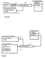
- FIG. 2 shows a detail of the block diagram of the electronic franking machine for a variant with OTP in the control device.
- sensors and actuators such as, for example, the encoders 13 and motor 12 shown in FIG. 1, can be connected to the OTP either directly or via I / O ports.
- a preferred variant of a microprocessor is an 8051 processor with a 16 kbyte on-chip EPROM (Philips 87C51FB).
- OTP type One Time Programmable
- the internal OTP-RAM has a memory area of 256 bytes.
- the invention further assumes that the entire program code required to operate a franking machine does not fit into the microprocessor-internal ROM, that is, an additional memory (EPROM) is required, which holds the greater part of the program code and which is available to the microprocessor via the microprocessor bus program code poses.
- EPROM additional memory
- An arrangement can advantageously be used which divides the program memory into memory segments, so-called memory banks, which allow the program memory area to be enlarged as desired via the address area of the microprocessor by using microprocessor port lines.
- FIG. 3 shows an overall flowchart for a franking machine with increased security according to the invention
- FIG. 4 shows an inventive detail thereof, namely a flowchart for the start and initialization routine.
- a program code in the non-readable internal OTP-ROM now allows several advantageous start security check routines, but at least those as they are named in FIG. 4 and explained in more detail in connection with FIGS. 7, 9 and 11.
- routines relate to the method for securing data and program code of an electronic franking machine and serve to improve the security of this electronic franking machine as part of a start security check in connection with its initialization.
- step 101 includes a start security check 1020.
- a start security check routine which uses its program code to check the most important externally held franking machine data and external program code, completely encapsulated in the internal ROM and RAM area of the OTP, can detect manipulations that are intentional against manipulation without the possibility of external manipulation State of the franking machine have been carried out and then effectively block further operation of the franking machine if the checking routines are not carried out without errors. In this case, the program flow remains in an endless loop in the OTP-ROM (error handling 1030). Only after the checks have been carried out without errors, the external storage media are used by the microprocessor (read EPROM, write RAM) and the system routine 200 is reached.
- FIG. 4 shows the schematic program flow diagram of all functions that are carried out in the OTP-ROM during the start security check of the franking machine.
- the start security check of the postage meter machine comprises a large number of routines, in addition to routine 1026 for securing the external program memory.
- routine 1021 which is not described in detail, denotes a check of the internal OTP-RAM with regard to its operability.
- Routines 1022 and 1023 compare the program version numbers, that is, determine whether the burned OTP forms a set of complete program code with the EPROM or whether another EPROM belongs to the OTP.
- Routine 1024 uses the data specified by the cliché EPROM to check whether there is a valid cliché EPROM or the cliché EPROM belonging to the above-mentioned set in the base. It should be mentioned as an advantage that the cliché EPROM may not only be inserted or replaced by the service technician, but also by any other authorized person. Special driver circuits (buffers), which are connected between the bus and EPROM socket (Fig. 2), prevent data from the franking machine inside being read out. On the other hand, data can be entered into the franking machine at any time via the base.
- routine 1026 concerns the protection of the external program memory and routine 1025 the protection of the externally accessible EPROM and the data stored therein from manipulation through security checks
- routines 1027 and 1028 perform a first check of security-relevant or postal register data in the external NVRAM and EEPROM made.
- Routine 1029 determines invalid or repairable data copies and, if necessary, eliminates the error.
- step 1029 - as is explained in more detail in the European application EP 615 211 A1 - at least one register check of the data structure of the postal register is carried out in order to log the errors.
- the routine 1026 for protecting the external program memory described in more detail below is based on the storage of a MAC in the memory module to be protected in each case. This has in addition to the necessary maintenance of data security above all the advantage of interchangeability of a faulty program EPROM's, without there being any need to be replaced at the same time the corresponding OTP.
- step 1026 uses the MAC method to check the integrity of the program code of external bus-coupled memories (EPROMs) before Processor bus access and while program is running.
- EPROMs external bus-coupled memories
- MAC message authentication code
- this MAC is formed once at a time T 1 at which manipulations are excluded and stored in a non-volatile memory area (block 71) of the external program memory of the microprocessor system.
- This time T1 is reached only by the franking machine manufacturer, this MAC (T1), for example during the program code data creation in the personal computer, being formed using the cryptographic checksum method (for example DES algorithm) and embedded in a defined memory area in the Eprom source data.
- the above-mentioned data are burned into the EPROM during programming.
- FIG. 6 shows such a formation of a MAC checksum using the DES method via external program EPROMs, the MAC being embedded in the memory area which is assigned to the memory area to be protected.
- a start routine and initialization of an electronic postage meter machine have already been proposed (without explaining this in more detail) in EP 660269, FIG. 2a (step 101). Furthermore, a routine for the initialization has been proposed, in which a security-relevant program code is stored in the OTP and in which a check sum is made in the OTP about the content of the external program memory and a comparison is made. However, the MAC was saved in a special OTP with internal NVRAM.
- FIG. 7 shows a sequence for checking an external program EPROM using MAC checksum methods for manipulations.
- the microprocessor system can use the same cryptographic (step 1026.2) checksum method over the memory area to be checked (step 1026.1) the MAC (in step 1026.2) at time T 2 and later (T 2 + n ) with the aid of the same secret key ( Form step 1026.3) and compare this MAC (T 2 + n ) with the MAC (T 1 ) taken from the EPROM (in step 1026.5) (see step 1026.6). With such a comparison, the data integrity can also be checked and manipulations of the memory contents can be recognized in a step 210 during the running time of the postage meter machine. In the event of a negative comparison (as determined in step 1026.7), appropriate measures can then be taken which prevent further operation of the franking machine (as in step 1030) or make manipulation more difficult or indicate such by suitable measures.
- the continuous MAC formation takes place - as shown in step 210 of FIG. 3 - after the start security check 1020 taking place in step 101 in each run of the operating program loop, so that a relevant MAC is formed and progressed over a larger number of program memory cells using the cryptographic checksum method can be compared with the respective stored MAC formed at time T1.
- each block B there is an associated MAC, which ensures the validity of the block. For example, one block is 4 KB. With a 128 KB EPROM there are 32 blocks and MAC checksums. Each block B is divided into several sub-blocks SB. These subblocks SB have a size of preferably 16 code words.
- a MAC is not calculated over the entire block during a run, since this would take too long.
- the MAC is calculated incrementally over each of the subblocks SB of a block B.
- the 16 code words of the respective sub-block SB are called up in the current block B in step 210-1 in order to use them as a total of a checksum and, if necessary, to subsequently form a MAC therefrom using DES encryption.
- the checksum is still zero.
- the block counter and the sub-block counter are also set to zero during the start routine.
- the checksum or MAC calculation for an entire block is interrupted according to the invention and continued in the next run.
- the checksum is accumulated with each pass and the MAC is then formed if necessary.
- the sub-block counter SBZ is incremented in step 210-2 in order to be able to accumulate again in step 210-1 in the next run and then to form the respective incremental MAC.
- a branch is made via a test step 210-3 to point e of the system routine if the maximum sub-block counter reading SBZmax has not yet been reached. Otherwise, all sub-blocks of a block have been run through and the final status of the checksum formation or the MAC formation has been reached.
- the aforementioned cumulative checksum or the MAC can be compared with an associated stored value.
- the associated stored value is a checksum or a MAC, which authenticates the subblock.
- the associated stored value can have been stored in the same EPROM to be checked or in another memory, for example in the internal OTP-ROM, at time T1, preferably at the franking machine manufacturer when programming the OTP.
- step 210-5 If it is determined in the subsequent step 210-5 that there is no identity and thus an error, an error routine (not shown) is activated branches. For example, a flag is set, which is evaluated in step 409 of the franking mode 400 (FIG. 5). Otherwise, if there is an identity, the authentication has been successfully completed and step 210-6 for block incrementation and step 210-7 for resetting the sub-block counter status and the checksum to the value zero are reached.
- the current block B is determined by the block counter status BZ of a block counter, which can be implemented in hardware or software.
- the current sub-block SB is determined by the sub-block counter SBZ of a block counter, which can also be implemented in hardware or software. Then the next subblock
- the proposed embodiment is adaptable to any system. Depending on the system used, it may make sense to choose the block size and the sub-block size differently. Too small a block size has the disadvantage that the number of MAC checksums increases and thus more memory space is also used. A too small sub-block size means that checksums are very often calculated and queries are made so that the time required increases again.
- the interval between the Checksum comparison can also be linked with a time monitoring (not shown), so that a stop of the program is recognized and leads to the same error handling as with a negative MAC comparison.
- FIG. 8 shows the formation of a MAC checksum using the DES method via EPROMs in the base of the open mail flap. This is a further advantageous application of the MAC method for checking the integrity of the data and the program code of Eproms, which are used in the franking machine with the mail flap open in the externally accessible base.
- manipulation could take place in such a way that a manipulator uses a manipulated program EPROM which, like a RESET eprom, takes control of the microprocessor system and thus specifically changes monetary values, entries or security entries in the franking machine, or that it uses a manipulated cliché eprom, that contains changed print data of the value stamp (place of the sender, post code of the sender) and would result in manipulation of the value stamp.
- a manipulator uses a manipulated program EPROM which, like a RESET eprom, takes control of the microprocessor system and thus specifically changes monetary values, entries or security entries in the franking machine, or that it uses a manipulated cliché eprom, that contains changed print data of the value stamp (place of the sender, post code of the sender) and would result in manipulation of the value stamp.
- the Figure 8 shows the protection of a further external EPROM's.
- the above-mentioned principle of MAC security via the memory areas can also be used here, since with a secret key which is hidden in the internal program memory (OTP-ROM) and cannot be read out, secure cryptographic functions can be implemented, the security of which is based on the use of this secret key . If you encrypt a checksum of these data areas (block 40) with a cryptographic function (block 60), for example DES, using these secret keys (block 40), a cryptographic checksum is created which represents the memory content.
- a cryptographic function block 60
- DES for example DES
- This MAC must be formed once at a time T 1 at which manipulations are excluded and is stored in the relevant eprom that is used in the cliché base (cliché prom, RESET-eprom) (block 41).
- This MAC (T 1 ) is formed, for example, during the program code data creation of the RESET EPROM in the personal computer and during the creation of cliché data using the cryptographic checksum method (e.g. DES algorithm) and embedded in the Eprom source data in a defined memory area.
- the cryptographic checksum method e.g. DES algorithm
- FIG. 9 shows the testing of an EPROM in the cliché base with MAC checksum methods for manipulation.
- the microprocessor system can use the same cryptographic checksum method (step 1025.2) via the memory area to be checked (step 1025.1) to form the MAC at the time T 2 of the start security check with the help (step 1025.3) of the same secret key and form this MAC (T 2 )
- This comparison (step 1025.6) enables the data integrity of the stamp data to be checked and manipulations of the program code to be identified (step 1025.7). In the event of a negative comparison, appropriate measures can then be taken to prevent the franking machine from continuing to operate (error handling 1030).
- FIG. 11 relates to checking selected postal data values in an electronic franking machine that are secured with a MAC. Such a check is carried out, for example, in step 1027 during the start and initialization routine, in communication mode 300 and in franking mode 400.
- the start security check in the start and initialization routine is therefore carried out using a selected checksum procedure within an OTP processor (ONE TIME PROGRAMMABLE), which internally stores the corresponding program parts and also the code for forming a MAC (MESSAGE AUTHENTIFICATION CODE) contains, which is why the manipulator cannot understand the type of checksum procedure.
- OTP processor ONE TIME PROGRAMMABLE
- MESSAGE AUTHENTIFICATION CODE MESSAGE AUTHENTIFICATION CODE
- Other security-relevant key data and processes are also stored exclusively in the interior of the OTP processor in order to provide MAC protection via the postal register.
- a manipulator could open the franking machine and make copies of this NVRAM or of another franking machine that contains a consistent data set (monetary values, register values, MACs, security data, FLAGs). Now he leads targeted manipulations of the data record, for example by reducing the billed franking value. In the event of an inspection or the next remote value specification, this manipulation would be noticed, for example, by checking the suspicious mode.
- serial number which is a unique identification of an individual franking machine, i.e. also the unique identification of the data record of the franking machine, in the MAC protection of register data
- a data record in NVRAM from another franking machine cannot be used because the serial number is also stored in another non-volatile memory (e.g. EEPROM) that cannot be removed from the franking machine.
- EEPROM non-volatile memory
- FIG. 10 shows the principle of this MAC generation.
- the MAC is stored in the reserved data area 50a in the NVRAM.
- the register MAC is stored several times in the NVRAM and is stored in the EEPROM for certain events, since this only allows a limited number of memory cycles.
- FIG. 11 shows the basic sequence of a check with the franking machine switched on.
- the microprocessor system can use the same cryptographic checksum method (step 1027.2) over the one to be checked Memory area 50a (step 1027.1) form the MAC (step 1027.4) at the time of the start security check 1020, before each franking (franking mode 400) and before each remote value specification (communication mode 300) with the aid of the same secret key (block 63, (step 1027.3) and generate this Compare MAC's (step 1027.4) with the extracted (step 1027.5) MAC (T1) in step 1027.6). In the event of a negative comparison (step 1027.7), appropriate measures can then be taken (step 1030) which prevent further operation of the franking machine.
- FIG. 5 shows the flowchart for a franking mode with test steps integrated according to the invention, which are carried out before printing. These also include the protection of selected postal data values in an electronic franking machine with a MAC, which is explained in more detail in FIGS. 10 and 11.
- the invention is based on the fact that after switching on, the postage value in the value print corresponding to the last entry before switching off the franking machine and the date in the day stamp corresponding to the current date are automatically specified that the variable data in the fixed data for the frame for the print and be electronically embedded for all associated data that remain unchanged.
- These variable data of the window contents are referred to below as window data and all fixed data for the value stamp, the day stamp and the advertising slogan stamp as framework data.
- the frame data can be taken from a first memory area of a read-only memory (ROM), which also serves as a program memory 11.
- the window data are taken from a second memory area and stored in accordance with the input in memory areas B j of the non-volatile main memory 5.
- This step includes an automatic routine for the call of pixel files, the assignment and embedding of pixel image data of the fixed and semi-variable as well variable print image data.
- the associated program is stored in the program EPROM and / or in the internal OTP-ROM. Since there is no program branching to program parts stored in the external program EPROM until step 1040, no manipulation of the print image creation can take place. Of course, they can also be found in the aforementioned memories at any time during the running time of the franking machine for the purpose of a new assembly to form an overall representation of a franking image.
- a preferred variant provides for the hexadecimal window data to be transmitted in run-length-coded form to the separate memory areas B 1 to B 4 of the non-volatile working memory 5a and to be stored there.
- the time in the clock / date module 8 continues to run even when the franking machine is switched off. If step 401 is thus reached in franking mode 400, data that has already been stored may have been used without manual or renewed external data input after the franking machine has been switched on.
- This setting relates in particular to the last setting of the postage meter with regard to the postage value, which is displayed in step 209 before the print data is prepared.
- the current variable pixel image data (date and postage value) are embedded in the fixed frame pixel image data. Subsequently, in step 301 of communication mode 300 or in further steps, such as in step 401 of franking mode 400, the input means are queried for any further inputs.
- step 209 the data from the aforementioned memory areas are assembled in accordance with a predetermined assignment to a pixel print image even before printing.
- the variable information in the window provided can be supplemented and modified later.
- only those parts of a graphic representation that are actually changed are stored in the non-volatile working memory when a change is made.
- the program memory 11 there is a first memory area A (among other things for the data of the constant parts of the franking image) and in the cliché EPROM there is another memory area A Ai (for the advertising cliché frame).
- the corresponding assignment of the respective cost center to the basic data is automatically queried after switching on.
- the cost center can be automatically assigned by entering a plate number and entered in the memory area C.
- the cost center must be re-entered into the memory area C each time it is switched on during the start routine.
- All alphanumeric characters or symbols are stored pixel by pixel as binary data in the character memory 9.
- the data for alphanumeric characters or symbols are stored in compressed form in the non-volatile working memory 5 in the form of hexadecimal numbers.
- the compressed data from the program memory 11 are converted with the help of the character memory 9 into a printed image having binary pixel data, which is stored in decompressed form in the volatile main memory 7.
- Working memories 7a, 7b and pixel memories 7c are used below to explain the invention, although this is physically preferably a single memory. For security reasons, the essential image generation program steps will take place in the internal OTP-RAM and are therefore not manipulable.
- the memory areas in the non-volatile working memory 5 can contain a large number of sub-memory areas, under which the respective data are stored in data records.
- control code and run length-coded frame or window data are alternately contained one after the other.
- the respective selected fixed data are transferred from the non-volatile program memory (PSP) 11 into first registers 701, 711, 721, ..., of the volatile working memory 7a, during which Transfer control codes are decoded and stored in a separate memory area of the working memory 7b.
- the respective selected window data for the postmark and the postage stamp are loaded into second registers 702, 712, 722, ....
- the registers of sub-memory areas are preferably formed in the memory area of the main memory 7a. In the preferred variant, these aforementioned registers are part of the microprocessor control 6. By decompression, the run-length-coded hexadecimal data are converted into corresponding binary pixel data.
- the invention furthermore consists in carrying out authenticity checks as a result of the print data input in step 1040 for frames and / or window data during the start and initialization routine 101 and in step 209 for security-relevant window data which were changed during the print data input, steps being taken if there is no authenticity Preventing a further program execution or a program branch leading externally from the OTP processor within the framework of the aforementioned system routine (200) and, if there is authenticity, steps for further program execution within the framework of the aforementioned system routine (200) are carried out.
- FIG. 14 shows a flow chart for securing security-relevant data in a freely accessible memory in an electronic franking machine.
- step 209-1 an entry is made for changing window data.
- the input is displayed in step 209-2 and then branches to a first test step 209-3 from a number of test steps 209-3 to 209-12.
- the external program memory also contains, for example, print data of the value stamp and other data, such as, for example, the sender's location, the postal code of the sender, etc., which are to be protected against manipulation by the method explained with reference to FIG.
- the test steps allow branching to one of the steps 209-4 to 209-11, if a different value, slogan, cliché or other data was selected when entering the data.
- the described method therefore has sufficient security, even though the MAC is only formed over the subarea in the EPROM that contains data corresponding to the selection. Then go over a step 209-20 branched back to step 209-1 to reset the loop counter. If all test steps 209-3 to 209-12 have been carried out without changing or selecting a new value or data, point e is reached.
- EP 0 660 269 A2 in which the program is checked by means of MAC only once at the start of the franking machine's runtime, is improved according to the invention by additional security checks of the individually subsequently changed window data.
- a subsequent exchange of the EPROM data can now advantageously be recognized during the running time of the franking machine in operation. This makes it impossible to tamper with or manipulate manipulated data at the moment the data is to be read in.
- steps 209-10 and 209-11 are explained in more detail. If no new entry is recognized (step 2090), a branch is made back to step 209-20. Before the MAC is used, the external EPROM data to be secured are completely loaded into the memory of the postage meter machine (step 2091) and a MAC is then formed via this RAM area (step 2092). This MAC is compared in step 2094 with a pre-calculated MAC (step 2093), which is stored at a suitable location, preferably in the external EPROM.
- a pre-calculated MAC step 2093
- step 209-13 is preferably branched to step 209-14.
- the external data can be stored in memory areas in the external EPROM store divided according to data records that are not required in the franking machine at the same time. This method saves time when checking the external data, because here a MAC only has to be formed over a partial area and has to be compared with that stored in the EPROM. The memory required for checking the MAC in the franking machine is thereby reduced. Do z. B. five external data areas (advertising clichés, election prints, etc.), for example, only 1/5 of the total amount of data needs to be transferred to the internal memory (less memory requirement) and also for forming the MAC only about 1/5 of the time is required. There is therefore no need to perform a check on all four data areas that are not required. Depending on the number of data areas to be protected, the same number of reference MACs is also in the external memory (EPROM or ROM).
- the MACs can also be located in the NV-RAM of the franking machine or even in the internal ROM of the franking machine. If the MACs are stored in the internal NV-RAM, this also has the advantage that an unsecured external EPROM or ROM is also authorized by entering a code in the franking machine. As a result, no fixed keys need to be used when generating the external ROMs; each franking machine can have its own key for generating the MACs.
- the MAC is formed from the unpacked data in RAM. This results in an additional saving of memory space, since compressed and decompressed data do not have to be stored in the franking machine's memory at the same time.
- the external data can also be uncompressed are present, the data then being transferred directly to the internal memory and then the MAC being formed via the internal memory or parts thereof.
- the separate safeguarding of the individual cliché parts also has the advantage that the time required to check the MAC when selecting a cliché remains low, since only the cliché parts that are currently needed are checked. Therefore, not only a MAC is provided for checking the data in a cliché memory (e.g. ROM), but each individual cliché (advertising cliché, election prints or slogan or other parts, such as the "paid fee” bar) has its own MAC.
- This data can be in an external ROM, in an external RAM, in an external NV-RAM, also on a chip card or in a combination of the aforementioned.
- the check is only carried out after the data has been transferred to the internal memory of the franking machine.
- step 209-11 If it is determined in step 209-11 that the MACs are not identical, the error can be displayed as in the present case in step 209-14 and the machine can then be blocked.
- Another possibility, e.g. B. when securing cliché data is to print a standard cliché for this case, which indicates manipulation. This cliché can be printed in place of the manipulated cliché or additionally. It is also possible to change another cliché (e.g. date, value) so that manipulation can be recognized.
- the constant parts of the franking image, once called up, are continuously decoded in the pixel memory area I in the volatile pixel memory 7c.
- the number strings (sTrings), which are entered for the generation of the input data with a keyboard 2 or via an electronic balance 22 connected to the input / output device 4 and calculating the postage value, are automatically stored in the memory area D of the non-volatile working memory 5. Plus stay too Records of the sub memory areas, for example B j , C etc., are obtained. This ensures that the last input values are retained even when the franking machine is switched off, so that after switching on the postage value in the value print is automatically specified in accordance with the last entry before the franking machine was switched off and the date in the day stamp is specified in accordance with the current date. If a scale 22 is connected, the postage value is taken from the storage area D. In step 401 it is checked whether there is an input. If a new input request is made in step 401, the process branches back to step 209.
- steps 402 and 404 branch to step 405 to increase a run counter and to check the number of runs to wait for the print output request.
- the letter to be franked is detected by a letter sensor and thus a print request is triggered. It is thus possible to branch to the accounting and printing routine in step 406. If there is no print output request (step 405), the process branches back to step 209 (point t).
- a communication request can be made at any time or another input can be made in accordance with the steps for data change 209, test request 212, register check 214 and input request 401.
- Steps 401 to 404 are carried out again.
- a branch is made from step 404 to step 408.
- the alternative query criterion can be queried in step 404 in order to set a standby flag in step 408 if there is still no print output request after a predetermined time.
- the standby flag can be queried in step 211 following communication mode 300. This does not branch to franking mode 400 until the checksum check has shown that all or at least selected programs are complete.
- step 405 If a print output request is recognized in step 405, further queries are made in subsequent steps 409 and 410 and in step 406. For example, in step 409 Presence of authentic register values (FIG. 11) and in step 410 the achievement of a further piece number criterion and in step 406 the register data collected in known manner for billing. In addition, as already explained with reference to FIG. 10, selected registers in the NVRAM of the franking machine are protected by MAC formation. If the number of items predetermined for franking was used up in the previous franking, ie number of items equal to zero, step 410 automatically branches to point e in order to enter communication mode 300 so that a new predetermined number of items S is again credited by the data center.
- step 410 the process branches from step 410 to the billing and printing routine in step 406.
- a special sleeping mode counter is prompted in step 406, that is to say during the accounting routine which takes place immediately before printing, to continue counting.
- the number of printed letters and the current values in the postal registers are registered in the non-volatile memories 5a, 5b of the franking machine in the accounting routine 406 in accordance with the entered cost center and are available for later evaluation.
- the register values can be queried in display mode 215. It is also provided that the register values or other service data are printed out with the print head of the franking machine for billing or control purposes. This can be done, for example, in the same way as the normal printing of the franking image, but another frame is initially selected for fixed image data, into which the variable data are inserted in accordance with the register values stored in the non-volatile memory NVM 5 or in the cost center memory, similar to that in FIG columns 1 to 2 or in claim 9, in the German patent application DE 42 24 955, for the formation and display in three multi-line information groups or for a required switchover to a corresponding mode is carried out in principle.
- variable pixel image data is also made for variable pixel image data to be embedded in the remaining pixel image data during printing.
- the compressed data are read from the working memories 5a, 5b and converted with the help of the character memory 9 into a printed image having binary pixel data, which likewise decompressed them Form is stored in volatile memory 7. Further details can be found in European applications EP 576 113 A2 and EP 578 042 A2.
- the pixel memory area in the pixel memory 7c is therefore provided for the selected decompressed data of the fixed parts of the franking image and for the selected decompressed data of the variable parts of the franking image.
- the actual printing routine takes place (in step 406).
- the main memory 7b and the pixel memory 7c are connected to the printer module 1 via a printer controller 14 which has a print register (P Reg ) 15 and an output logic.
- the pixel memory 7c is connected on the output side to a first input of the printer controller 14, at the other control inputs of which output signals from the microprocessor control device 6 are applied.
- step 202 When changing to the system routine 200 - as shown in FIG. 3 - after a further step 201 for calling up data, in particular sleeping mode quantity data, it is first checked in step 202 whether the criteria for entering the sleeping mode are met . If this is the case, a branch is made to step 203 in order to display at least one warning by means of the display unit 3. In this case, further steps 204 to 206 can be run through before branching to step 209 becomes. If this is not the case, a branch is also made to step 209. After the steps, point t is reached in any case.
- step 301 a query is made in step 301 as to whether there is a transaction request. If this is not the case, communication mode 300 is exited and point f, i. operating mode 290 reached. If relevant data were transmitted in communication mode, branch to step 213 for data evaluation. Or otherwise, if the non-transmission is determined in step 211, branch to step 212. It is now checked whether corresponding entries have been made in order to go to test mode 216 when test request 212 is made, otherwise to go to display mode 215 when register status check 214 is intended. If this is not the case, the point d, i.e. the franking mode 400 is reached.
- a statistical and / or error evaluation is carried out in step 213 in order to obtain further current data which can also be called up in step 201 after branching to the system routine 200. If point e, ie the beginning of the communication mode 300 explained below, is reached, a query is made in step 301 as to whether there is a transaction request. Such can be provided, for example, for reloading credit and quantity or updating other relevant data.
- the user selects the communication or remote value setting mode of the franking machine by entering the identification number (eight-digit postage request number) and by pressing the predetermined T key. If the desired input parameter is displayed correctly, this is confirmed by pressing the predetermined T key of the input means 2 again. The input parameter is edited if necessary. A display corresponding to the input then appears in the display unit 3.
- the transmission of the input parameter via the MODEM connection is started and the input is checked.
- the rest of the process runs automatically, with the process being accompanied by a corresponding display.
- the franking machine checks whether a MODEM is connected and ready for operation. If this is not the case, the process branches to step 310 to indicate that the transaction request must be repeated. Otherwise, the franking machine reads the dialing parameters, consisting of the dial-out parameters (main / extension, etc.) and the telephone number from an NVRAM memory area F and sends them to the modem 23 with a dial request command. The connection required for communication is then established via the MODEM 23 with the data center After a predetermined number n of unsuccessful redials for the purpose of establishing a connection, a branch is made back to point e via a display step 310.
- a transaction carried out during the communication with encrypted messages comprises a default value for a credit reload value which is transmitted to the remote data center and / or that another transaction carried out during the communication with encrypted messages contains a specific quantity S 'for a sleeping Fashion includes.
- One of the transaction requests leads to a specially secured credit reload in the franking machine.
- the postal registers present outside of the processor in the cost center memory are preferably also secured during the credit reload by means of a time control. If the franking machine is observed with an emulator / debugger, for example, then it is likely that the communication and accounting routines will not run within a predetermined time. If so, i.e. the routines require considerably more time if this were recognized in the postage meter machine and, as a result, critical memory areas are irretrievably deleted. This prevents the franking machine from continuing to operate.
- the DES algorithm is preferably applied to the keys required for the remote value specification in order to store them in cryptified form.
- the data transmission from the franking machine to the data center is also secured in communication mode 300 with a DES algorithm, for which a secret DES key is required.
- This secret DES key is formed in the communication mode 300 by the encrypted keys during the running time of the franking machine, i.e. are decrypted in the OTP during the communication mode 300 in order to load a secret key KAct into the internal OTP-RAM.
- FIG. 12 shows the input encryption of the remote value specification DES key K Fix for securing the remote value specification DES key K Fix. before manipulation.
- each franking machine receives a fixed remote value specification key K Fix via its user interface 2, 3, which key must in principle be kept hidden in the NVRAM.
- the remote value setting key in step 60 with the cryptographic function, D ATA E ncryption- S tandard (DES), the encrypted secret key K stored Kfix using the OTP-ROM (64 step).
- the encrypted secret key K Fix is now stored in the external data memory (NVRAM).
- FIG. 13 shows which steps must be carried out at the runtime of the postage meter machine for a remote value specification so that the DES key KAct is formed from the encrypted K fix value in the external NVRAM and is held in the processor-internal RAM for the time of the remote value specification procedure .
- the secret key K Kfix is taken from the internal OTP-ROM (block 64) and encrypted key Crypt K Fix is taken from the NVRAM.
- the block 60 in FIG. 13 shows the decryption DES key K Fix and a storage in the internal OTP-RAM for the remote value specification in the Block 65.
- the franking machine performs the regularly and / or when switched on Register check and can thus recognize the missing information if the machine was opened without authorization. The franking machine is then blocked.
- the potential manipulator of a franking machine has to overcome several thresholds, which of course takes a certain amount of time. If there is no connection from the franking machine to the data center at certain time intervals, the franking machine becomes suspect. It can be assumed that anyone who tampering with the franking machine will hardly report back to the data center.
- the control device 6 has a microprocessor or an OTP.
- the OTP also houses non-volatile memories and other circuits in a common housing.
- the internal non-volatile memory includes, for example, program memory and in particular also the possibility of setting save bits which prevent the internal non-volatile memory from being read from the outside.
- These security bits are set in the OTP during the manufacture of the franking machine. Observing such security-relevant routines, such as billing routines, with an emulator / debugger would also lead to a change in the timing, which can be determined by the OTP.
- This also includes a clock generator / counter circuit for the specification of time intervals or clock cycles, for example for time-out generation or printer control.
- the clock / counter circuit When a certain time has elapsed and the expected event has not occurred, the clock / counter circuit generates an interrupt which reports to the microprocessor that the time has elapsed without success, whereupon the microprocessor takes further measures.
- the clock generator / counter circuit is used for program runtime monitoring. A known number of clock cycles for the program execution of predetermined program parts is assumed. Before the start of the routine, the counter of the clock / counter circuit is preset or reset in a predetermined manner. After the start of the program routine, the counter status is continuously changed in accordance with the clock pulses of the clock generator. After the critical predetermined program parts have been processed, the state of the counter is queried by the microprocessor and compared with the expected value.
- the franking machine When crossing In the event of a predetermined deviation in the running time of critical or security-relevant program parts, the franking machine can therefore no longer be operated for franking (kill mode 1). If a manipulator carries out an unauthorized intervention, the franking machine is effectively put out of operation during the runtime by switching to the first mode.
- the register status is checked during an inspection. If necessary, a test impression with the value 0 can be made. In the event of a repair by the on-site service, the franking machine may have to be accessed.
- the error registers can be read out, for example, with the help of a special service EPROM, which is inserted in the place of the advert EPROM. If the processor does not access this EPROM slot, access to the data lines is usually prevented by special driver circuits (buffers) shown in FIG. 2. The data lines, which can be reached through an unsealed housing door, cannot be contacted without authorization.
- Another variant is the reading out of error register data by a service computer connected via an interface, the interface then having to have appropriate security measures.
- the check sum for the kill mode 2 is formed in the OTP via the content of the external program memory PSP 11 and the result is compared with a predetermined value stored in the OTP. This is preferably done in step 101 when the postage meter machine is started, or in step 213 when the postage meter machine is operated in standby mode.
- the standby mode is reached when there is no input or print request for a predetermined time.
- Step 405 - shown in FIG. 5 - in franking mode 400 therefore also comprises a further query for a time lapse which, if the time is exceeded, ultimately returns to point t and thus to point Input routine according to step 209 leads. If the query criterion is met, a standby flag is set as in step 408 and a branch is made back directly to point s to system routine 200 or to point t without the billing and printing routine being executed in step 406. The standby flag is queried later in step 211 and reset after the checksum check in step 213 if no attempted manipulation is detected.
- step 211 The query criterion in step 211 is expanded to include the question of whether the standby flag is set, i.e. whether the standby mode is reached.
- step 213 is also branched to.
- the advantage of this method in connection with the first mode is that the manipulation attempt is statistically recorded in step 213.
- a flow control is used according to the invention, which is explained below.
- Such a flow control is carried out by changing a count value in a memory at at least one point during the execution of the program routine. After execution of the program routine, the changed count value is compared with a predetermined count value assigned to this program routine. If branches are run through during program execution, different count values can result. In a subsequent evaluation, a plausibility test is carried out or it can be determined which branches have been run through. This is possible because the change in the count value takes place by multiplication by a specific prime number assigned to the respective program part. In a later evaluation, only a prime number decomposition then has to be carried out.
- the overall flowchart for a security system shown in FIG. 3 has steps 201 to 206 for monitoring further criteria. If one of the security criteria is violated the franking machine enters a sleeping mode, for example if a connection to the data center has not yet been established after the consumption of a predetermined number of pieces.
- the franking machine and the data center each agree on a predetermined number of items S, i.e. the amount that can be franked until the next connection. If communication fails (quantity control), the franking machine slows down its mode of operation (sleeping mode variant 1).
- step 203 comprises a sub-step for error statistics in accordance with the statistics and error evaluation mode 213.
- the franking machine requires a connection to the data center in the manner known from US Pat. No. 3,255,439. If the connection is established, the data center checks the register status. If the reload cannot be carried out, the data center prevents it from further operation by means of a signal transmitted to the franking machine. If the connection was established shortly after the signaling performed by the franking machine and the register statuses are not criticized, the franking machine can be switched back to the operating mode without any further extraordinary inspection. For this purpose, new current data are transmitted, for example for a credit and for the permitted number of pieces, which can be franked until the next connection.
- the data center can differentiate between automatic and normal communication based on the transmitted signaling code.
- the former will always take place if the user of the franking machine has overlooked or ignored the requests for communication and has omitted appropriate input actions. In the event of repetition, a special inspection can be ordered if manipulation is suspected.
- Communication mode 300 can then be accessed directly from franking mode Point e are branched back. In this way, other inputs can also be made, for example in accordance with the steps of test request 212 or register check 214. Only if a branch is made to franking mode 400 is it determined again in step 410 according to the decision criterion whether automatic communication is required. This is preferably the case if the predetermined number of pieces has been used up.
- step 213 is also reached.
- the current data are determined or loaded, which are called in step 201 and then required again for the comparison in step 202.
- the transmitted decision criterion is preferably the new number S '.
- An alternative variant consists in that the decision criterion is the new credit transmitted for franking and in evaluation mode 213 the new number of items S 'is determined internally in the franking machine.
- communication with the data center no longer includes the new number S ', but is only required to trigger the calculation in evaluation mode 213.
- the calculation takes place internally in the franking machine and at the same time in parallel in the data center using the same methods based on the transmitted register data.
- R1 can be queried and statistically evaluate. If R1 becomes larger and larger, the same reload amount can be reloaded in ever larger reloading periods, or the number of pieces that can be franked until the next communication is set.
- a plausibility check of all franking machines in use is carried out in the data center at regular intervals. In this process, the machines are identified and reported to the postal authority whose franking behavior appears suspicious or has been manipulated. Another security measure (error overflow mode) may be provided in the franking machine. In the second mode, this can be carried out in addition to or instead of sleeping mode variant 1 or sleeping mode variant 2. If the query criterion in step 202 is met, ie if a predetermined number of errors is exceeded, the reaction time of the postage meter machine slows down in step 203, this status being reported to the operator of the postage meter machine simultaneously via the display. In the further steps, the procedure can be similar to that already explained in connection with FIGS. 2 and 5.
- the postage meter machine stores both internal and operating errors and attempts at manipulation in an error register for logging purposes, for example up to the number 999. If the status of the number of errors being exceeded is not eliminated, for example as part of an inspection by a service provider or by resetting during communication with the data center , the response time can be increased further to make any manipulation more difficult. The number of errors is then further logged, ie up to a predetermined number, for example in step 213.
- a first variant provides for the response time, for example the time until the start of printing, to be increased linearly with the number of errors.
- the execution of the program is neither modified nor prevented, but only delayed.
- non-critical program parts that are not monitored by time supervision (kill mode 1) or flow control are called multiple times, such as the error display. This means that the effectiveness of the program remains essentially unchanged.
- reaction time is increased by one level, whereby the levels can relate to seconds, minutes, hours, days, ... etc.
- an increase in the response time can also be provided for each incorrect operation.
- an electronic time lock is actuated for this purpose.
- a progressive increase in the reaction time period is preferably provided in the operating program in order to make manipulation more difficult.
- step 213 is partially or completely called up as a sub-step in connection with other steps.
- the statistics and error mode is part of step 203 and the billing and printing routine according to step 406 in franking mode 400, which is shown in more detail in FIGS. 3 and 5. If a severe accounting error occurs, the machine is blocked in step 406. However, if an error occurs during the initialization phase in step 101, the machine stops and displays a specific error code.
- the invention is not limited to the present embodiments. Rather, a number of variants are conceivable which make use of the solution shown, even in the case of fundamentally different types.
Landscapes
- Engineering & Computer Science (AREA)
- Theoretical Computer Science (AREA)
- Physics & Mathematics (AREA)
- General Physics & Mathematics (AREA)
- Devices For Checking Fares Or Tickets At Control Points (AREA)
- Storage Device Security (AREA)
Applications Claiming Priority (2)
| Application Number | Priority Date | Filing Date | Title |
|---|---|---|---|
| DE1995134530 DE19534530A1 (de) | 1995-09-08 | 1995-09-08 | Verfahren zur Absicherung von Daten und Programmcode einer elektronischen Frankiermaschine |
| DE19534530 | 1995-09-08 |
Publications (2)
| Publication Number | Publication Date |
|---|---|
| EP0762338A2 true EP0762338A2 (fr) | 1997-03-12 |
| EP0762338A3 EP0762338A3 (fr) | 2000-01-26 |
Family
ID=7772452
Family Applications (1)
| Application Number | Title | Priority Date | Filing Date |
|---|---|---|---|
| EP96250192A Ceased EP0762338A3 (fr) | 1995-09-08 | 1996-09-06 | Procédé pour sécuriser les données et le code de programme d'une machine d'affranchissement |
Country Status (2)
| Country | Link |
|---|---|
| EP (1) | EP0762338A3 (fr) |
| DE (1) | DE19534530A1 (fr) |
Cited By (10)
| Publication number | Priority date | Publication date | Assignee | Title |
|---|---|---|---|---|
| EP0930586A3 (fr) * | 1997-12-15 | 2000-09-27 | Francotyp-Postalia AG & Co. | Dispositif et méthode pour l'échange de données entre une machine d'affranchissement et des cartes à puce |
| EP0927969A3 (fr) * | 1997-12-15 | 2000-09-27 | Francotyp-Postalia AG & Co. | Machine à affranchir avec dispositif de lecture/écriture de cartes à puce |
| EP0927968A3 (fr) * | 1997-12-15 | 2000-09-27 | Francotyp-Postalia AG & Co. | Machine à affranchir avec dispositif de lecture/écriture de cartes à puce |
| EP0927971A3 (fr) * | 1997-12-15 | 2000-09-27 | Francotyp-Postalia AG & Co. | Procédé et dispositif postal avec une unité de lecture/écriture de cartes à puce pour le rechargement de données de changement dans une carte à puce |
| EP0927970A3 (fr) * | 1997-12-15 | 2000-09-27 | Francotyp-Postalia AG & Co. | Machine à affranchir avec dispositif de lecture/écriture de cartes à puce |
| EP0908852A3 (fr) * | 1997-09-16 | 2000-12-27 | Ascom Hasler Mailing Systems AG | Interface homme-machine améliorée |
| EP1063619A1 (fr) | 1999-06-15 | 2000-12-27 | Francotyp-Postalia Aktiengesellschaft & Co. | Module de sécurité et procédé pour protection du registre postal contre la manipulation |
| EP1202223A2 (fr) | 2000-07-27 | 2002-05-02 | Francotyp-Postalia AG & Co. | Machine postale et procédé pour l'initialisation |
| EP1069492A3 (fr) * | 1999-06-15 | 2006-04-19 | Francotyp-Postalia GmbH | Module et méthode de sécurité pour la surveillance de sécurité d'un système |
| EP1095343A4 (fr) * | 1998-06-15 | 2007-05-02 | Ascom Hasler Mailing Sys Inc | Technique assurant la securite de la configuration d'un systeme postal d'affranchissement |
Families Citing this family (3)
| Publication number | Priority date | Publication date | Assignee | Title |
|---|---|---|---|---|
| DE19731304B4 (de) * | 1997-07-14 | 2005-02-24 | Francotyp-Postalia Ag & Co. Kg | Verfahren zur Statistikmodusnachladung und zur statistischen Erfassung nach Statistikklassen bei der Speicherung eines Datensatzes |
| DE19830055B4 (de) | 1998-06-29 | 2005-10-13 | Francotyp-Postalia Ag & Co. Kg | Verfahren zur sicheren Übertragung von Dienstdaten an ein Endgerät und Anordnung zur Durchführung des Verfahrens |
| DE10300609A1 (de) * | 2003-01-10 | 2004-07-29 | Wincor Nixdorf International Gmbh | Rückwirkungsfreie Geräteschnittstelle |
Family Cites Families (6)
| Publication number | Priority date | Publication date | Assignee | Title |
|---|---|---|---|---|
| US4726025A (en) * | 1985-10-16 | 1988-02-16 | Sperry Corporation | Generation and diagnostic verification of complex timing cycles |
| JPS63196936A (ja) * | 1987-02-10 | 1988-08-15 | Nec Corp | プログラム起動チエツク方式 |
| GB8704883D0 (en) * | 1987-03-03 | 1987-04-08 | Hewlett Packard Co | Secure information storage |
| DE4129302A1 (de) * | 1991-09-03 | 1993-03-04 | Helmut Lembens | Frankiermaschine |
| US5448641A (en) * | 1993-10-08 | 1995-09-05 | Pitney Bowes Inc. | Postal rating system with verifiable integrity |
| DE4344476A1 (de) * | 1993-12-21 | 1995-06-22 | Francotyp Postalia Gmbh | Verfahren zur Verbesserung der Sicherheit von Frankiermaschinen |
-
1995
- 1995-09-08 DE DE1995134530 patent/DE19534530A1/de not_active Ceased
-
1996
- 1996-09-06 EP EP96250192A patent/EP0762338A3/fr not_active Ceased
Cited By (16)
| Publication number | Priority date | Publication date | Assignee | Title |
|---|---|---|---|---|
| EP0908852A3 (fr) * | 1997-09-16 | 2000-12-27 | Ascom Hasler Mailing Systems AG | Interface homme-machine améliorée |
| US6295523B1 (en) | 1997-09-16 | 2001-09-25 | Ascom Hasler Mailing Systems Ag | Man-machine interface |
| EP0927970A3 (fr) * | 1997-12-15 | 2000-09-27 | Francotyp-Postalia AG & Co. | Machine à affranchir avec dispositif de lecture/écriture de cartes à puce |
| US6418422B1 (en) | 1997-12-15 | 2002-07-09 | Francotype-Postalia Ag & Co. | Postage meter machine with a chip card write/read unit and method for operating same |
| EP0930586A3 (fr) * | 1997-12-15 | 2000-09-27 | Francotyp-Postalia AG & Co. | Dispositif et méthode pour l'échange de données entre une machine d'affranchissement et des cartes à puce |
| EP0927968A3 (fr) * | 1997-12-15 | 2000-09-27 | Francotyp-Postalia AG & Co. | Machine à affranchir avec dispositif de lecture/écriture de cartes à puce |
| US6199752B1 (en) | 1997-12-15 | 2001-03-13 | Francotyp-Postalia Ag & Co. | Postage meter machine with a chip card write/read unit and method for operating same |
| EP0927969A3 (fr) * | 1997-12-15 | 2000-09-27 | Francotyp-Postalia AG & Co. | Machine à affranchir avec dispositif de lecture/écriture de cartes à puce |
| EP0927971A3 (fr) * | 1997-12-15 | 2000-09-27 | Francotyp-Postalia AG & Co. | Procédé et dispositif postal avec une unité de lecture/écriture de cartes à puce pour le rechargement de données de changement dans une carte à puce |
| EP1095343A4 (fr) * | 1998-06-15 | 2007-05-02 | Ascom Hasler Mailing Sys Inc | Technique assurant la securite de la configuration d'un systeme postal d'affranchissement |
| US6362724B1 (en) | 1999-06-15 | 2002-03-26 | Francotyp-Postalia Ag & Co. | Security module and method for securing computerized postal registers against manipulation |
| EP1069492A3 (fr) * | 1999-06-15 | 2006-04-19 | Francotyp-Postalia GmbH | Module et méthode de sécurité pour la surveillance de sécurité d'un système |
| EP1063619A1 (fr) | 1999-06-15 | 2000-12-27 | Francotyp-Postalia Aktiengesellschaft & Co. | Module de sécurité et procédé pour protection du registre postal contre la manipulation |
| EP1202223A2 (fr) | 2000-07-27 | 2002-05-02 | Francotyp-Postalia AG & Co. | Machine postale et procédé pour l'initialisation |
| EP1202223A3 (fr) * | 2000-07-27 | 2005-06-08 | Francotyp-Postalia AG & Co. KG | Machine postale et procédé pour l'initialisation |
| US7974927B2 (en) | 2000-07-27 | 2011-07-05 | Francotyp-Postalia Gmbh | Mailing machine and initialization method |
Also Published As
| Publication number | Publication date |
|---|---|
| EP0762338A3 (fr) | 2000-01-26 |
| DE19534530A1 (de) | 1997-03-13 |
Similar Documents
| Publication | Publication Date | Title |
|---|---|---|
| EP0660269B1 (fr) | Procédé pour améliorer la sécurité de machines à affrauchir | |
| EP0762337A2 (fr) | Procédé et dispositif pour augmenter la protection contre la manipulation de données critiques | |
| EP1118964B1 (fr) | Procédé et dispositif pour vérifier un motif destiné à la sécurité | |
| US5805711A (en) | Method of improving the security of postage meter machines | |
| CH675496A5 (fr) | ||
| EP0892368B1 (fr) | Procédé pour le téléchargement de données statistiques et de recensement en ensembles statistiques lors du chargement des données | |
| DE69736246T2 (de) | Vorrichtung zur gesicherten Kryptographischen Datenverarbeitung und zum Schutz von Speicherermitteln für Frankiermaschinen | |
| EP0762338A2 (fr) | Procédé pour sécuriser les données et le code de programme d'une machine d'affranchissement | |
| DE19534528A1 (de) | Verfahren zur Veränderung der in Speicherzellen geladenen Daten einer elektronischen Frankiermaschine | |
| EP1035516B1 (fr) | Système pour un module de sécurité | |
| DE19912781A1 (de) | Verfahren zum Schutz eines Sicherheitsmoduls und Anordnung zur Durchführung des Verfahrens | |
| DE19757653C2 (de) | Verfahren und postalisches Gerät mit einer Chipkarten-Schreib/Leseeinheit zum Nachladen von Änderungsdaten per Chipkarte | |
| EP1063619B1 (fr) | Module de sécurité et procédé pour protection du registre postal contre la manipulation | |
| EP1035518A2 (fr) | Procédé de protection d'un module de sécurité et ensemble pour mettre en oeuvre ledit procédé | |
| EP0969420B1 (fr) | Procédé pour sécuriser la transmission de données de service à un terminal et dispositif pour la mise en oeuvre de ce procédé | |
| EP0717379B1 (fr) | Procédé pour l'amélioration de la sécurité des machines à timbrer pendant le transfert du crédit | |
| EP1061479A2 (fr) | Dispositif et procédé pour générer un motif destiné à la sécurité | |
| DE19534529C2 (de) | Verfahren zur Erhöhung der Manipulationssicherheit von kritischen Daten | |
| EP0996097A9 (fr) | Procédé pour améliorer la sécurité de machines à affranchir pendant le transfert du crédit | |
| DE19534527C2 (de) | Verfahren zur Erhöhung der Manipulationssicherheit von kritischen Daten | |
| EP1857981A2 (fr) | Agencement et procédé destinés à la fabrication d'un affranchissement | |
| DE29522056U1 (de) | Anordnung zur Erhöhung der Manipulationssicherheit von kritischen Daten | |
| DE102006022210A1 (de) | Anordnung und Verfahren zum Erstellen eines Frankierabdrucks |
Legal Events
| Date | Code | Title | Description |
|---|---|---|---|
| PUAI | Public reference made under article 153(3) epc to a published international application that has entered the european phase |
Free format text: ORIGINAL CODE: 0009012 |
|
| AK | Designated contracting states |
Kind code of ref document: A2 Designated state(s): CH DE FR GB IT LI |
|
| PUAL | Search report despatched |
Free format text: ORIGINAL CODE: 0009013 |
|
| AK | Designated contracting states |
Kind code of ref document: A3 Designated state(s): CH DE FR GB IT LI |
|
| 17P | Request for examination filed |
Effective date: 20000214 |
|
| 17Q | First examination report despatched |
Effective date: 20020408 |
|
| RAP1 | Party data changed (applicant data changed or rights of an application transferred) |
Owner name: FRANCOTYP-POSTALIA AG & CO. KG |
|
| STAA | Information on the status of an ep patent application or granted ep patent |
Free format text: STATUS: THE APPLICATION HAS BEEN REFUSED |
|
| 18R | Application refused |
Effective date: 20030426 |