EP0765731A2 - Procédé pour la fabrication de films minces - Google Patents
Procédé pour la fabrication de films minces Download PDFInfo
- Publication number
- EP0765731A2 EP0765731A2 EP96306981A EP96306981A EP0765731A2 EP 0765731 A2 EP0765731 A2 EP 0765731A2 EP 96306981 A EP96306981 A EP 96306981A EP 96306981 A EP96306981 A EP 96306981A EP 0765731 A2 EP0765731 A2 EP 0765731A2
- Authority
- EP
- European Patent Office
- Prior art keywords
- resin
- layers
- laminate
- species
- films
- Prior art date
- Legal status (The legal status is an assumption and is not a legal conclusion. Google has not performed a legal analysis and makes no representation as to the accuracy of the status listed.)
- Withdrawn
Links
Images



Classifications
-
- B—PERFORMING OPERATIONS; TRANSPORTING
- B32—LAYERED PRODUCTS
- B32B—LAYERED PRODUCTS, i.e. PRODUCTS BUILT-UP OF STRATA OF FLAT OR NON-FLAT, e.g. CELLULAR OR HONEYCOMB, FORM
- B32B27/00—Layered products comprising a layer of synthetic resin
- B32B27/06—Layered products comprising a layer of synthetic resin as the main or only constituent of a layer, which is next to another layer of the same or of a different material
- B32B27/08—Layered products comprising a layer of synthetic resin as the main or only constituent of a layer, which is next to another layer of the same or of a different material of synthetic resin
-
- B—PERFORMING OPERATIONS; TRANSPORTING
- B29—WORKING OF PLASTICS; WORKING OF SUBSTANCES IN A PLASTIC STATE IN GENERAL
- B29C—SHAPING OR JOINING OF PLASTICS; SHAPING OF MATERIAL IN A PLASTIC STATE, NOT OTHERWISE PROVIDED FOR; AFTER-TREATMENT OF THE SHAPED PRODUCTS, e.g. REPAIRING
- B29C48/00—Extrusion moulding, i.e. expressing the moulding material through a die or nozzle which imparts the desired form; Apparatus therefor
- B29C48/03—Extrusion moulding, i.e. expressing the moulding material through a die or nozzle which imparts the desired form; Apparatus therefor characterised by the shape of the extruded material at extrusion
- B29C48/07—Flat, e.g. panels
- B29C48/08—Flat, e.g. panels flexible, e.g. films
-
- B—PERFORMING OPERATIONS; TRANSPORTING
- B29—WORKING OF PLASTICS; WORKING OF SUBSTANCES IN A PLASTIC STATE IN GENERAL
- B29C—SHAPING OR JOINING OF PLASTICS; SHAPING OF MATERIAL IN A PLASTIC STATE, NOT OTHERWISE PROVIDED FOR; AFTER-TREATMENT OF THE SHAPED PRODUCTS, e.g. REPAIRING
- B29C48/00—Extrusion moulding, i.e. expressing the moulding material through a die or nozzle which imparts the desired form; Apparatus therefor
- B29C48/03—Extrusion moulding, i.e. expressing the moulding material through a die or nozzle which imparts the desired form; Apparatus therefor characterised by the shape of the extruded material at extrusion
- B29C48/09—Articles with cross-sections having partially or fully enclosed cavities, e.g. pipes or channels
-
- B—PERFORMING OPERATIONS; TRANSPORTING
- B29—WORKING OF PLASTICS; WORKING OF SUBSTANCES IN A PLASTIC STATE IN GENERAL
- B29C—SHAPING OR JOINING OF PLASTICS; SHAPING OF MATERIAL IN A PLASTIC STATE, NOT OTHERWISE PROVIDED FOR; AFTER-TREATMENT OF THE SHAPED PRODUCTS, e.g. REPAIRING
- B29C48/00—Extrusion moulding, i.e. expressing the moulding material through a die or nozzle which imparts the desired form; Apparatus therefor
- B29C48/03—Extrusion moulding, i.e. expressing the moulding material through a die or nozzle which imparts the desired form; Apparatus therefor characterised by the shape of the extruded material at extrusion
- B29C48/09—Articles with cross-sections having partially or fully enclosed cavities, e.g. pipes or channels
- B29C48/10—Articles with cross-sections having partially or fully enclosed cavities, e.g. pipes or channels flexible, e.g. blown foils
-
- B—PERFORMING OPERATIONS; TRANSPORTING
- B29—WORKING OF PLASTICS; WORKING OF SUBSTANCES IN A PLASTIC STATE IN GENERAL
- B29C—SHAPING OR JOINING OF PLASTICS; SHAPING OF MATERIAL IN A PLASTIC STATE, NOT OTHERWISE PROVIDED FOR; AFTER-TREATMENT OF THE SHAPED PRODUCTS, e.g. REPAIRING
- B29C48/00—Extrusion moulding, i.e. expressing the moulding material through a die or nozzle which imparts the desired form; Apparatus therefor
- B29C48/16—Articles comprising two or more components, e.g. co-extruded layers
- B29C48/18—Articles comprising two or more components, e.g. co-extruded layers the components being layers
- B29C48/21—Articles comprising two or more components, e.g. co-extruded layers the components being layers the layers being joined at their surfaces
-
- B—PERFORMING OPERATIONS; TRANSPORTING
- B29—WORKING OF PLASTICS; WORKING OF SUBSTANCES IN A PLASTIC STATE IN GENERAL
- B29C—SHAPING OR JOINING OF PLASTICS; SHAPING OF MATERIAL IN A PLASTIC STATE, NOT OTHERWISE PROVIDED FOR; AFTER-TREATMENT OF THE SHAPED PRODUCTS, e.g. REPAIRING
- B29C48/00—Extrusion moulding, i.e. expressing the moulding material through a die or nozzle which imparts the desired form; Apparatus therefor
- B29C48/25—Component parts, details or accessories; Auxiliary operations
- B29C48/30—Extrusion nozzles or dies
- B29C48/32—Extrusion nozzles or dies with annular openings, e.g. for forming tubular articles
- B29C48/335—Multiple annular extrusion nozzles in coaxial arrangement, e.g. for making multi-layered tubular articles
- B29C48/337—Multiple annular extrusion nozzles in coaxial arrangement, e.g. for making multi-layered tubular articles the components merging at a common location
- B29C48/338—Multiple annular extrusion nozzles in coaxial arrangement, e.g. for making multi-layered tubular articles the components merging at a common location using a die with concentric parts, e.g. rings, cylinders
-
- B—PERFORMING OPERATIONS; TRANSPORTING
- B29—WORKING OF PLASTICS; WORKING OF SUBSTANCES IN A PLASTIC STATE IN GENERAL
- B29C—SHAPING OR JOINING OF PLASTICS; SHAPING OF MATERIAL IN A PLASTIC STATE, NOT OTHERWISE PROVIDED FOR; AFTER-TREATMENT OF THE SHAPED PRODUCTS, e.g. REPAIRING
- B29C48/00—Extrusion moulding, i.e. expressing the moulding material through a die or nozzle which imparts the desired form; Apparatus therefor
- B29C48/25—Component parts, details or accessories; Auxiliary operations
- B29C48/36—Means for plasticising or homogenising the moulding material or forcing it through the nozzle or die
- B29C48/50—Details of extruders
- B29C48/695—Flow dividers, e.g. breaker plates
- B29C48/70—Flow dividers, e.g. breaker plates comprising means for dividing, distributing and recombining melt flows
- B29C48/705—Flow dividers, e.g. breaker plates comprising means for dividing, distributing and recombining melt flows in the die zone, e.g. to create flow homogeneity
-
- B—PERFORMING OPERATIONS; TRANSPORTING
- B29—WORKING OF PLASTICS; WORKING OF SUBSTANCES IN A PLASTIC STATE IN GENERAL
- B29D—PRODUCING PARTICULAR ARTICLES FROM PLASTICS OR FROM SUBSTANCES IN A PLASTIC STATE
- B29D7/00—Producing flat articles, e.g. films or sheets
- B29D7/01—Films or sheets
-
- B—PERFORMING OPERATIONS; TRANSPORTING
- B32—LAYERED PRODUCTS
- B32B—LAYERED PRODUCTS, i.e. PRODUCTS BUILT-UP OF STRATA OF FLAT OR NON-FLAT, e.g. CELLULAR OR HONEYCOMB, FORM
- B32B1/00—Layered products having a non-planar shape
- B32B1/08—Tubular products
-
- B—PERFORMING OPERATIONS; TRANSPORTING
- B32—LAYERED PRODUCTS
- B32B—LAYERED PRODUCTS, i.e. PRODUCTS BUILT-UP OF STRATA OF FLAT OR NON-FLAT, e.g. CELLULAR OR HONEYCOMB, FORM
- B32B38/00—Ancillary operations in connection with laminating processes
- B32B38/0012—Mechanical treatment, e.g. roughening, deforming, stretching
-
- B—PERFORMING OPERATIONS; TRANSPORTING
- B32—LAYERED PRODUCTS
- B32B—LAYERED PRODUCTS, i.e. PRODUCTS BUILT-UP OF STRATA OF FLAT OR NON-FLAT, e.g. CELLULAR OR HONEYCOMB, FORM
- B32B38/00—Ancillary operations in connection with laminating processes
- B32B38/0012—Mechanical treatment, e.g. roughening, deforming, stretching
- B32B2038/0028—Stretching, elongating
-
- B—PERFORMING OPERATIONS; TRANSPORTING
- B32—LAYERED PRODUCTS
- B32B—LAYERED PRODUCTS, i.e. PRODUCTS BUILT-UP OF STRATA OF FLAT OR NON-FLAT, e.g. CELLULAR OR HONEYCOMB, FORM
- B32B2597/00—Tubular articles, e.g. hoses, pipes
Definitions
- the present invention relates to a process for conveniently producing resin films having a thickness so small that they cannot be produced easily by conventional commercial resin film production processes, such as the T-die (tenter) process, the inflation process, etc.
- Known commercial processes for producing resin films in an isolated form may include the T-die (tenter) process, the inflation process, etc.
- the lower limit of thickness of films obtained by these processes has been restricted to ca. 10 ⁇ m, and the commercial production of films having a smaller thickness has not been successful so far.
- a principal object of the present invention is to provide a process for producing resin films, by which thin films having a thickness on the order of 10 pm or smaller can be produced effectively.
- the resin laminate in the form of a sheet or film (hereinafter sometimes inclusively referred to as a "laminate resin sheet" without an intention of restricting the thickness thereof) caused to be in contact with a solvent, has two major surfaces, to which the respective component resin layers are laminated obliquely and exposed, and which have much larger areas than the edge surfaces thereof, so that a solvent effectively penetrates into the layers of the the resin having a substantial solubility in the solvent (hereinafter sometimes referred to as a "soluble resin”) to dissolve the layers.
- soluble resin a solvent effectively penetrates into the layers of the the resin having a substantial solubility in the solvent
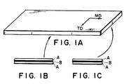
- Figure 1A is a perspective view of a conventional laminate resin sheet
- Figures 1B and 1C are schematic views, of an MD section and a TD section, respectively, of the resin sheet.
- Figure 2A is a perspective view of a laminate resin sheet used in an embodiment of the process of the present invention
- Figures 2B and 2C are schematic views, of an MD section and a TD section, respectively, of the resin sheet
- Figure 2D is a schematic plan view of the resin sheet.
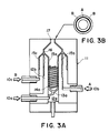
- Figure 3A is a longitudinal sectional view of a conventional multi-layer spiral die and Figure 3B is a cross-sectional view of a product sheet obtained therefrom.
- Figure 4A is a longitudinal sectional view of a spiral die suitable for production of a laminate resin sheet used in the present invention
- Figure 4B is a schematic circumferentially cross-sectional view of a product sheet obtained therefrom.
- Figure 5 is a schematic perspective enlarged illustration of an essential part of the spiral die shown in Figure 4A.
- Figures 1A, 1B and 1C are a schematic perspective view, a partial sectional view in an MD direction parallel to a forming or extrusion axis, and a partial sectional view in a TD direction perpendicular to the forming or extrusion axis, respectively, of a conventional laminate resin sheet as used in the above-mentioned process of U.S. Patent No. 4,874,568, wherein the component resin layers A and B uniformly extend to the edges in parallel to the two major surfaces both in the MD and TD directions. Accordingly, only edge surfaces having a very small area can be used for contact with a solvent for dissolving a soluble resin B, so that the isolation of insoluble resin layers A by dissolution of the soluble resin layer B takes a long time.
- Figures 2A, 2B and 2C are a schematic sectional view, a partial sectional view in an MD direction and a partial sectional view in a TD direction, respectively, of a laminate resin sheet 1 as an embodiment of the resin laminate used in an embodiment of the process according to the present invention prepared by using a spiral die in a preferred example of process for producing the laminate resin sheet.
- the laminate resin sheet 1 has an MD section showing the resin layers A and B laminated alternately and parallel to the two major surfaces ( Figure 2B) but has a TD section showing the resin layers A and B laminated alternately and obliquely so that the respective resin layers A and B reach the two major surfaces 1a and 1b of the laminate resin sheet 1 ( Figure 2C).
- the individual resin layers A and B form with respect to the two major surfaces 1a and 1b an angle ⁇ , which however is not so large as shown in Figure 2C but may be in the range of larger than 0 deg. and at most 4 deg., particularly 0.001 - 0.4 deg.
- a laminate resin sheet as described above may be subjected to dipping in a solvent, or sprinkling, application or spraying of a solvent, etc., so as to cause at least one of the two major surfaces thereof to contact the solvent, thereby selectively dissolving and removing the soluble resin layers B to recover isolated films of the insoluble resin layer A.
- the soluble resin layers B and the insoluble resin layers A are alternately exposed to the two major surfaces having a much larger area than the edge surfaces thereof, so that the solvent contacting (or applied on) at least one major surface can effectively penetrate into the soluble resin layers B to allow quick removable by dissolution thereof.
- a plurality of laminate films each having a lamination structure of C/A can be obtained at a time by the selective dissolution of the soluble resin layers B.
- each of two types of films A and C is respectively obtained in a plurality in an isolated form.
- two types of films, i.e., films A and laminate films C/A are respectively obtained in a plurality.
- two types of films C and laminate films C/A are respectively obtained in a plurality.
- fine particles of, e.g., 0.1 - 5 ⁇ m in particle size (diameter) insoluble with the insoluble resin A and soluble in the solvent for the soluble resin B may be admixed in the insoluble resin layers A, so as to provide gas-permeable or liquid-permeable films of the insoluble resin A having micropores as traces of the fine particles after the selective dissolution of the resin layers B with the solvent.
- a soluble resin and a solvent may include the following:
- FIG. 3A is a schematic longitudinal sectional view of a conventional spiral die for laminate production.
- a resin B extruded from an extruder 10a (not illustrated) and introduced into a spiral die 11 is guided to a so-called (reverse) tournament-form manifold 13a (only one of a plurality thereof being shown) disposed in proximity with the outer periphery of a first die ring (innermost ring) 12a where the resin B is uniformly diverged and introduced into a plurality of spiral (flow) grooves 14a disposed on the outer periphery of the first die ring 12a.
- a so-called (reverse) tournament-form manifold 13a only one of a plurality thereof being shown
- Each spiral groove has a depth which gradually decreases as it goes in the proceeding direction (generally upward).
- the resin B flowing along the spiral groove 14a spirally proceeds upwards while forming an overflowing or leakage stream at a spacing from a second die ring 12b until it flows upwards as a uniform axial tubular stream along a groove-free tubular path 15a to reach a joining point 16.
- a resin A extruded from an extruder 10b and introduced into the spiral die 11 is similarly diverged and caused to form an overflowing or leakage stream to consequently form a uniform axial tubular stream flowing through a tubular path 15b and reach the joining point 16.
- a melted resin stream B extruded from an extruder 10c similarly is diverged, forms an overflowing or leakage stream and then forms a uniform axial tubular stream flowing through a tubular path 15c to reach the joining point 16. Then, at the joining point 16, these three tubular streams of melted resins B, A and B are laminated to be extruded through a die lip 17 to form a laminate tube.
- the laminate tube thus extruded out of the die lip 17 forms a laminated tubular product having a cross-section as shown in Figure 3B and comprising an intermediate layer of resin A sandwiched with layers of resin B.
- either one of the resins A and B is a soluble resin and the other is an insoluble resin.
- Figure 4A is a schematic sectional view of a spiral die 21 preferably used for producing a laminate resin sheet used in a process of the present invention.
- Streams of melted resins A and B extruded out of extruders 20a and 20b and introduced into the spiral die 21 are respectively diverged through (reverse) tournament-form manifolds (not shown but described hereinafter) each per se being similar to the one denoted by reference numeral 13a shown in Figure 3A and introduced into respective spiral grooves 24a and 24b each provided in a plurality.
- the thus-extruded laminate tube forms a laminated tubular product having a circumferential cross-section (i.e., a cross-section in a transverse direction (TD) perpendicular to the extrusion axis) schematically as shown in Figure 4B wherein layers of the resin A and B are alternately laminated obliquely to the two major surfaces.
- TD transverse direction
- FIG 5 is a schematic perspective view of a part enclosed within a frame III drawn with a dot-and-dash line in Figure 4A for illustrating the manner of distribution-lamination of the melted resin streams A an B.
- the melted resin streams A and B extruded out of the extruders (20a and 20b in Figure 4A) and introduced into the spiral die 21 first reach tournament manifold points 23al and 23bl, from which the melted resin streams A and B are repeatedly diverged through manifold points 23a2, 23b2 ... and flow through final manifold points 23a3 and 23b3 to be introduced into final paths 28a, 28b, 28a, 28b ... in a distribution section.
- the melted resin streams A and B are caused to alternately flow into spiral grooves 24a, 24b, 24a, 24b...
- the initial points of the spiral grooves 24a, 24b, 24a, 24b ... may preferably be disposed substantially on an identical circular circumferential line on the inner die ring 22a.
- the melted resin streams A and B having entered the spiral grooves 24a and 24b initially exclusively proceed as spiral streams along the spiral grooves 24a and 24b but gradually form leakage streams overflowing spiral ridges 22aa of the inner die ring 22a and flow upwards in a path 22ab between the inner die ring 22a, particularly the spiral ridges 22aa thereof, and the outer die ring 22b.
- the melted resin streams A and B overflow out of the respective spiral grooves as if they form melted films flowing circumferentially.
- each resin stream forms an outer surface portion of the product laminate tube at the initial point of an associated spiral groove and gradually proceed toward the inner surface while being laminated or covered with other resin streams to reach the inner surface when it moves by the spreading angle .
- each of the melted resin steams A and B is laminated obliquely for a spreading angle ( Figure 4B).
- the spreading angle can be controlled for each of the resins A and B by changing the initial depth, gradual thickness-reducing rate, etc., of the spiral groove 24a or 24b but may be in the range of generally 60 - 720 degrees, preferably 80 - 360 degrees, more preferably 130 - 230 degrees.
- the resultant laminate is liable to be accompanied with a thickness irregularity.
- the pressure in the spiral die at the time of the forming is liable to be excessive, so that the forming of the laminate becomes difficult.
- the laminate tube extruded out of the die lip 27 may be optionally subjected to an inflation step for circumferentially enlarging and thinning the laminate and then shaped into a laminate resin sheet as shown in Figures 2A - 2D used in the present invention by slitting the tubular laminate ordinarily in a direction parallel to the forming axis.
- a plurality (n, a positive integer ⁇ 2) of mutually different resin species (A, B, C ...) for lamination may preferably be 2 - 4.
- the number (m, a positive integer satisfying n ⁇ m) of spiral grooves, i.e., the total number of spiral grooves 24a, 24b, etc. may preferably be 4 - 256, further preferably 8 - 128, particularly preferably 16 - 64.
- the number of thicknesswise laminated layers at a particular planar position of the laminate resin film may preferably be 4 - 100 layers, particularly 6 - 20 layers.
- the number of thicknesswise laminated layers may be calculated as m x ⁇ /360 from the above-mentioned number of spiral grooves m and spreading angle ⁇ .
- the total thickness of the laminate resin product or laminated resin film may be controlled in a wide range, e.g., by using a melt-extruded parison as it is or controlling the degree of inflation (stretching ratio), and may for example be in the range of 10 ⁇ m - 1 mm, preferably 15 - 200 ⁇ m.
- the resins A, B, ..., etc., used in the above-described process may desirably have a melt viscosity (as measured at 200 °C and 25 sec -1 ) of 100 - 5000 Pa.s, preferably 300 - 2000 Pa.s, more preferably 400 - 1200 Pa.s.
- the resin A used was ethylene-vinyl acetate copolymer modified by grafting with maleic anhydride ("MODIC E-300K” (available from Mitsubishi Kagaku K.K.) having a melt viscosity at 200 °C and 25 sec -1 of 708 Pa.s, hereinafter indicated as "EVA")
- the resin B used was nylon 6 - nylon 12 copolymer ("AMILAN CM6541X3" (available from Toray K.K.) having a melt-viscosity at 200 °C and 25 sec -1 of 814 Pa.s, hereinafter indicated as "6-12 Ny”).
- the laminate resin sheet (tube) was biaxially stretched at 3x3 times (MDxTD) by inflation into a thickness of 20 ⁇ m.
- the resultant inflated laminate resin sheet (tube) had a circular peripheral length of 900 mm and was then cut into a length of 150 mm in MD direction while in the form of the tube.
- the laminate sheet (tube) was dipped and held in a large excess of hexafluoroisopropanol solvent at 30 °C for 3 hours to completely dissolve the 6-12Ny layers, whereby 8 EVA films each in a thickness of ca. 2.2 ⁇ m, an MD-length of 150 mm and a TD-length of 375 mm were obtained simultaneously.
- a laminate resin sheet (tube) was prepared in the same manner as in Example 1 except for using, as the resin A, 6-12Ny (the same as one used in Example 1) and, as the resin B, ethylene vinyl acetate copolymer saponified product (indicated as EVOH"; "EVAL EPE 105A” (available from Kuraray K.K.) having an ethylene content of 44 mol. %, a saponification degree of 99.4 % and a melt-viscosity (at 200 °C, 25 sec -1 ) of 901 Pa.s.
- EVOH ethylene vinyl acetate copolymer saponified product
- the laminate resin sheet (tube) was biaxially stretched at 3x3 times (MDxTD) by inflation into a thickness of 20 ⁇ m.
- the inflated laminate resin sheet (tube) had a peripheral length of 900 mm, was cut into a length of 150 mm in MD direction while in the form of the tube and was dipped for 3 hours in a large excess of dimethylsulfoxide solvent at 30 °C to completely dissolve the EVOH layers, whereby 8 films of 6-12Ny each having a thickness of ca. 2.2 ⁇ m, an MD-length of 150 mm, and a TD-length of 375 mm were obtained simultaneously.
- Gap between a spiral ridge (on the inner die ring) and the outer die ring initial 0 mm terminal 1.5 mm
- Diameter of the inner die ring initial 100 mm terminal 97 mm
- the resin A used was 6-12Ny (the same as one used in Example 1)
- the resin B was EVOH (the same as one used in Example 2).
- the resultant laminate resin sheet (tube) had a peripheral length of 300 mm and was then cut into a length of 150 mm in MD direction while in the form of the tube.
- the laminate sheet (tube) was dipped and held in a large excess of dimethylsulfoxide solvent at 30 °C for 3 hours to completely dissolve the EVOH layers, whereby 16 films of 6-12Ny each having a thickness of ca. 10 ⁇ m, an MD-length of 150 mm and a TD-length of 133 mm were obtained simultaneously.
- a laminate resin sheet (tube) was extruded in the same manner as in Example 3 except that the total thickness was changed to 180 ⁇ m.
- the laminate resin sheet (tube) was biaxially stretched at 3x3 times by inflation into a thickness of 20 ⁇ m.
- the inflated laminate resin sheet (tube) had a peripheral length of 900 mm, was cut into a length of 150 mm in MD direction while in the form of the tube and was dipped for 3 hours in a large excess of dimethylsulfoxide solvent at 30 °C to completely dissolve the EVOH layers, whereby 16 films of 6-12Ny each having a thickness of ca. 1.3 ⁇ m, an MD-length of 150 mm, and a TD-length of 400 mm were obtained simultaneously.
- a laminate resin sheet (tube) was prepared in the same manner as in Example 4 except for using, as the resin B, EVA (the same as one used in Example 1).
- the laminate resin sheet (tube) was biaxially stretched at 3x3 times (MDxTD) by inflation into a thickness of 20 ⁇ m.
- the inflated laminate resin sheet (tube) had a peripheral length of 900 mm, was cut into a length of 150 in MD direction while in the form of the tube mm and was dipped for 3 hours in a large excess of 1,2,4-trichlorobenzene solvent heated at 130 °C to completely dissolve the EVA layers, whereby 16 films of 6-12Ny each having a thickness of ca. 1.3 ⁇ m, an MD-length of 150 mm, and a TD-length of 400 mm were obtained simultaneously.
- Gap between a spiral ridge (on the inner die ring) and the outer die ring initial 0.5 mm terminal 1.25 mm
- Diameter of the inner die ring initial 100 mm terminal 97.5 mm
- melt-viscosities referred to herein are based on values measured in the following manner.
- Measurement was made by using a rotational viscometer ("DSR", available from Rheometrics Co.) under the following conditions: Test temperature 200 °C Shear rate 0.1 - 1000 sec -1 Geometry parallel plates Gap 2 mm
- melt viscosity values described herein were calculated at a shear rate of 25 sec -1 based on the above measurement.
- the resultant laminate sheet (tube) had a peripheral length of 300 mm, was cut into a length of 150 mm in MD direction while in the form of the tube and was dipped for 3 hours in a large excess of dimethylsulfoxide solvent at 30 °C to completely dissolve the EVOH layer whereby a single tubular film of 6-12Ny having a thickness of ca. 90 ⁇ m, an MD-length of 150 mm and a TD-length of 300 mm was obtained.
- a laminate sheet (tube) prepared in Comparative Example 1 was biaxially stretched at 3x3 times (MDxTD) by inflation to form a 20 ⁇ m-thick inflated laminate resin sheet (tube) including a 6-12Ny layer and an EVOH layer respectively in a thickness of 10 ⁇ m for comparison with the one of Example 4.
- the inflated laminate sheet (tube) had a peripheral length of 900 mm, was cut into a length of 150 mm in MD direction while in the form of the tube and was dipped for 3 hours in a large excess of dimethylsulfoxide solvent at 30 °C to completely dissolve the EVOH layer whereby a single tubular film of 6-12Ny having a thickness of ca. 10 ⁇ m, an MD-length of 150 mm and a TD-length of 900 mm was obtained.
- Examples 1 - 5 according to the present invention provides 1.3 to 10 ⁇ m-thick films were effectively produced in 8 - 16 sheets each in a single dissolution step.
Landscapes
- Engineering & Computer Science (AREA)
- Mechanical Engineering (AREA)
- Manufacturing & Machinery (AREA)
- Manufacture Of Macromolecular Shaped Articles (AREA)
- Shaping By String And By Release Of Stress In Plastics And The Like (AREA)
- Compositions Of Macromolecular Compounds (AREA)
- Extrusion Moulding Of Plastics Or The Like (AREA)
Applications Claiming Priority (2)
| Application Number | Priority Date | Filing Date | Title |
|---|---|---|---|
| JP27206095A JP3502703B2 (ja) | 1995-09-27 | 1995-09-27 | 薄膜製造法 |
| JP272060/95 | 1995-09-27 |
Publications (2)
| Publication Number | Publication Date |
|---|---|
| EP0765731A2 true EP0765731A2 (fr) | 1997-04-02 |
| EP0765731A3 EP0765731A3 (fr) | 1997-11-12 |
Family
ID=17508545
Family Applications (1)
| Application Number | Title | Priority Date | Filing Date |
|---|---|---|---|
| EP96306981A Withdrawn EP0765731A3 (fr) | 1995-09-27 | 1996-09-25 | Procédé pour la fabrication de films minces |
Country Status (2)
| Country | Link |
|---|---|
| EP (1) | EP0765731A3 (fr) |
| JP (1) | JP3502703B2 (fr) |
Cited By (1)
| Publication number | Priority date | Publication date | Assignee | Title |
|---|---|---|---|---|
| WO2013011079A1 (fr) * | 2011-07-20 | 2013-01-24 | Plastika Kritis S.A. | Filière de co-extrusion concentrique et procédé d'extrusion de film thermoplastique multicouche |
Families Citing this family (1)
| Publication number | Priority date | Publication date | Assignee | Title |
|---|---|---|---|---|
| TW200427503A (en) | 2003-05-27 | 2004-12-16 | Kureha Chemical Ind Co Ltd | Process for producing thermoplastic resin molding |
Family Cites Families (6)
| Publication number | Priority date | Publication date | Assignee | Title |
|---|---|---|---|---|
| DE2248818C2 (de) * | 1972-10-05 | 1981-10-15 | Bayer Ag, 5090 Leverkusen | Dünne porenfreie Polycarbonatfolien und -filme |
| JPS57176125A (en) * | 1981-04-22 | 1982-10-29 | Sekisui Chem Co Ltd | Production of extremely thin resin film |
| US4874568A (en) | 1988-09-26 | 1989-10-17 | The Dow Chemical Company | Process of making a porous membrane |
| JP3471924B2 (ja) | 1994-09-21 | 2003-12-02 | 呉羽化学工業株式会社 | スパイラルダイおよびこれを用いる積層体製造方法 |
| JP3315271B2 (ja) * | 1994-09-21 | 2002-08-19 | 呉羽化学工業株式会社 | 積層樹脂成形体 |
| JP3450559B2 (ja) | 1995-12-15 | 2003-09-29 | 呉羽化学工業株式会社 | 伸縮寸法回復性の良好なガスバリアー性樹脂フィルム |
-
1995
- 1995-09-27 JP JP27206095A patent/JP3502703B2/ja not_active Expired - Fee Related
-
1996
- 1996-09-25 EP EP96306981A patent/EP0765731A3/fr not_active Withdrawn
Cited By (4)
| Publication number | Priority date | Publication date | Assignee | Title |
|---|---|---|---|---|
| WO2013011079A1 (fr) * | 2011-07-20 | 2013-01-24 | Plastika Kritis S.A. | Filière de co-extrusion concentrique et procédé d'extrusion de film thermoplastique multicouche |
| CN103764369A (zh) * | 2011-07-20 | 2014-04-30 | 帕拉斯蒂卡克里蒂斯公司 | 同心共挤出模具以及挤出多层热塑性膜的方法 |
| CN103764369B (zh) * | 2011-07-20 | 2016-08-17 | 帕拉斯蒂卡克里蒂斯公司 | 同心共挤出模具以及挤出多层热塑性膜的方法 |
| US9868244B2 (en) | 2011-07-20 | 2018-01-16 | Plastika Kritis S.A. | Concentric co-extrusion die for extruding a multilayer thermoplastic film |
Also Published As
| Publication number | Publication date |
|---|---|
| JPH0987398A (ja) | 1997-03-31 |
| EP0765731A3 (fr) | 1997-11-12 |
| JP3502703B2 (ja) | 2004-03-02 |
Similar Documents
| Publication | Publication Date | Title |
|---|---|---|
| EP0703055A1 (fr) | Filière spirale et méthode de fabrication d'une feuille stratifiée utilisant cette filière | |
| KR100699120B1 (ko) | 감소된 분열 성향을 지닌 배터리 격리판 | |
| EP0019564B1 (fr) | Procédé et appareillage pour l'extrusion de tubes plastiques à parois composites | |
| EP0337719B1 (fr) | Procédé pour la fabrication d'une film polymère thermoplastiqué et matériau d'amortissement fabriqué à partir de celui-ci. | |
| CA2671948A1 (fr) | Stratifies croises de films orientes, procede de fabrication associe, et matrice de coextrusion appropriee au procede | |
| JPS621404A (ja) | 多層複合中空繊維状膜及びその製造法 | |
| EP0041311A1 (fr) | Fabrication de pellicules multicouches utilisant des déchets de résines synthétiques | |
| JP2006501078A5 (fr) | ||
| EP0010895A1 (fr) | Procédé de fabrication de feuilles à couches multiples en matières thermoplastiques par coextrusion à passage unique et adaptateur d'alimentation de résine fondue utilisé à cet effet | |
| CA1191007A (fr) | Pellicules stratifiees a couches orientees independamment | |
| EP0703066B1 (fr) | Produit polymérique stratifié oblique | |
| JPS585226A (ja) | 薄膜フイルム | |
| US4522854A (en) | Integral film tear strip | |
| JP2588484B2 (ja) | チューブの共押出しブロー成形による半結晶性溶融ポリマーからのフィルムの製造方法 | |
| JPS5878730A (ja) | 積層ポリマーシートの押出し方法 | |
| JP3502703B2 (ja) | 薄膜製造法 | |
| CA1131868A (fr) | Methode de production de pellicules en plastique | |
| US4496516A (en) | Process for forming oriented multi-layer films having a different orientation distribution between layers | |
| JP2004134391A (ja) | 電池セパレータ | |
| JPH1119999A (ja) | 共押出発泡体の製造方法 | |
| JP3597317B2 (ja) | スパイラルダイおよびこれを用いる積層体製造方法 | |
| JPH09254231A (ja) | ガス透過性フィルム、その製造方法および前駆体 | |
| EP0163571A1 (fr) | Procédé de fabrication par extrusions multiples de tubes allégés, rigides, en matiéres thermoplastiques | |
| JPH09164577A (ja) | 波状褶曲断面構造を有する積層樹脂成形体およびその製造法 | |
| JP3450559B2 (ja) | 伸縮寸法回復性の良好なガスバリアー性樹脂フィルム |
Legal Events
| Date | Code | Title | Description |
|---|---|---|---|
| PUAI | Public reference made under article 153(3) epc to a published international application that has entered the european phase |
Free format text: ORIGINAL CODE: 0009012 |
|
| 17P | Request for examination filed |
Effective date: 19961015 |
|
| AK | Designated contracting states |
Kind code of ref document: A2 Designated state(s): DE GB NL |
|
| PUAL | Search report despatched |
Free format text: ORIGINAL CODE: 0009013 |
|
| AK | Designated contracting states |
Kind code of ref document: A3 Designated state(s): DE GB NL |
|
| STAA | Information on the status of an ep patent application or granted ep patent |
Free format text: STATUS: THE APPLICATION HAS BEEN WITHDRAWN |
|
| 18W | Application withdrawn |
Withdrawal date: 19971210 |