EP0768541A2 - Verfahren und Vorrichtung zum Auffinden und Schützen von Personen und Objekten - Google Patents
Verfahren und Vorrichtung zum Auffinden und Schützen von Personen und Objekten Download PDFInfo
- Publication number
- EP0768541A2 EP0768541A2 EP96203438A EP96203438A EP0768541A2 EP 0768541 A2 EP0768541 A2 EP 0768541A2 EP 96203438 A EP96203438 A EP 96203438A EP 96203438 A EP96203438 A EP 96203438A EP 0768541 A2 EP0768541 A2 EP 0768541A2
- Authority
- EP
- European Patent Office
- Prior art keywords
- detector
- door
- detection
- lobe
- antenna
- Prior art date
- Legal status (The legal status is an assumption and is not a legal conclusion. Google has not performed a legal analysis and makes no representation as to the accuracy of the status listed.)
- Granted
Links
- 238000000034 method Methods 0.000 title claims description 23
- 238000001514 detection method Methods 0.000 claims description 120
- 230000006870 function Effects 0.000 claims description 18
- 230000005855 radiation Effects 0.000 description 21
- 238000012545 processing Methods 0.000 description 13
- 238000005516 engineering process Methods 0.000 description 11
- 238000005096 rolling process Methods 0.000 description 11
- 230000035945 sensitivity Effects 0.000 description 10
- 230000008901 benefit Effects 0.000 description 9
- 230000000694 effects Effects 0.000 description 9
- 229910052782 aluminium Inorganic materials 0.000 description 8
- XAGFODPZIPBFFR-UHFFFAOYSA-N aluminium Chemical compound [Al] XAGFODPZIPBFFR-UHFFFAOYSA-N 0.000 description 8
- 230000008569 process Effects 0.000 description 8
- 238000013459 approach Methods 0.000 description 7
- 238000005259 measurement Methods 0.000 description 7
- 210000002105 tongue Anatomy 0.000 description 7
- 238000010586 diagram Methods 0.000 description 5
- 239000011159 matrix material Substances 0.000 description 5
- 238000009826 distribution Methods 0.000 description 4
- RYGMFSIKBFXOCR-UHFFFAOYSA-N Copper Chemical compound [Cu] RYGMFSIKBFXOCR-UHFFFAOYSA-N 0.000 description 3
- 230000008859 change Effects 0.000 description 3
- 229910052802 copper Inorganic materials 0.000 description 3
- 239000010949 copper Substances 0.000 description 3
- 238000005520 cutting process Methods 0.000 description 3
- 238000004519 manufacturing process Methods 0.000 description 3
- 229910052751 metal Inorganic materials 0.000 description 3
- 239000002184 metal Substances 0.000 description 3
- 238000012986 modification Methods 0.000 description 3
- 230000004048 modification Effects 0.000 description 3
- 230000002745 absorbent Effects 0.000 description 2
- 239000002250 absorbent Substances 0.000 description 2
- 230000009471 action Effects 0.000 description 2
- 230000003321 amplification Effects 0.000 description 2
- 230000000903 blocking effect Effects 0.000 description 2
- 230000001419 dependent effect Effects 0.000 description 2
- 230000005672 electromagnetic field Effects 0.000 description 2
- 230000002349 favourable effect Effects 0.000 description 2
- 230000005669 field effect Effects 0.000 description 2
- 239000003292 glue Substances 0.000 description 2
- 238000003754 machining Methods 0.000 description 2
- 238000003199 nucleic acid amplification method Methods 0.000 description 2
- 230000005693 optoelectronics Effects 0.000 description 2
- 230000003071 parasitic effect Effects 0.000 description 2
- 230000002028 premature Effects 0.000 description 2
- 238000002310 reflectometry Methods 0.000 description 2
- 229910001369 Brass Inorganic materials 0.000 description 1
- 239000004593 Epoxy Substances 0.000 description 1
- 230000006978 adaptation Effects 0.000 description 1
- 239000002390 adhesive tape Substances 0.000 description 1
- 230000006399 behavior Effects 0.000 description 1
- 239000010951 brass Substances 0.000 description 1
- 239000000470 constituent Substances 0.000 description 1
- 238000002788 crimping Methods 0.000 description 1
- 238000005553 drilling Methods 0.000 description 1
- 230000005670 electromagnetic radiation Effects 0.000 description 1
- 239000004744 fabric Substances 0.000 description 1
- 238000003780 insertion Methods 0.000 description 1
- 230000037431 insertion Effects 0.000 description 1
- 238000009434 installation Methods 0.000 description 1
- 239000000463 material Substances 0.000 description 1
- 238000001465 metallisation Methods 0.000 description 1
- 238000012544 monitoring process Methods 0.000 description 1
- 230000010363 phase shift Effects 0.000 description 1
- 230000003252 repetitive effect Effects 0.000 description 1
- 238000003860 storage Methods 0.000 description 1
- 239000000758 substrate Substances 0.000 description 1
- 230000001360 synchronised effect Effects 0.000 description 1
- 238000012360 testing method Methods 0.000 description 1
- 238000013519 translation Methods 0.000 description 1
- 238000002604 ultrasonography Methods 0.000 description 1
- 238000003466 welding Methods 0.000 description 1
- 238000004804 winding Methods 0.000 description 1
- 210000002268 wool Anatomy 0.000 description 1
Images









Classifications
-
- G—PHYSICS
- G01—MEASURING; TESTING
- G01S—RADIO DIRECTION-FINDING; RADIO NAVIGATION; DETERMINING DISTANCE OR VELOCITY BY USE OF RADIO WAVES; LOCATING OR PRESENCE-DETECTING BY USE OF THE REFLECTION OR RERADIATION OF RADIO WAVES; ANALOGOUS ARRANGEMENTS USING OTHER WAVES
- G01S13/00—Systems using the reflection or reradiation of radio waves, e.g. radar systems; Analogous systems using reflection or reradiation of waves whose nature or wavelength is irrelevant or unspecified
- G01S13/02—Systems using reflection of radio waves, e.g. primary radar systems; Analogous systems
- G01S13/50—Systems of measurement based on relative movement of target
- G01S13/52—Discriminating between fixed and moving objects or between objects moving at different speeds
- G01S13/56—Discriminating between fixed and moving objects or between objects moving at different speeds for presence detection
-
- E—FIXED CONSTRUCTIONS
- E05—LOCKS; KEYS; WINDOW OR DOOR FITTINGS; SAFES
- E05F—DEVICES FOR MOVING WINGS INTO OPEN OR CLOSED POSITION; CHECKS FOR WINGS; WING FITTINGS NOT OTHERWISE PROVIDED FOR, CONCERNED WITH THE FUNCTIONING OF THE WING
- E05F15/00—Power-operated mechanisms for wings
- E05F15/40—Safety devices, e.g. detection of obstructions or end positions
- E05F15/42—Detection using safety edges
- E05F15/43—Detection using safety edges responsive to disruption of energy beams, e.g. light or sound
-
- E—FIXED CONSTRUCTIONS
- E05—LOCKS; KEYS; WINDOW OR DOOR FITTINGS; SAFES
- E05F—DEVICES FOR MOVING WINGS INTO OPEN OR CLOSED POSITION; CHECKS FOR WINGS; WING FITTINGS NOT OTHERWISE PROVIDED FOR, CONCERNED WITH THE FUNCTIONING OF THE WING
- E05F15/00—Power-operated mechanisms for wings
- E05F15/60—Power-operated mechanisms for wings using electrical actuators
- E05F15/603—Power-operated mechanisms for wings using electrical actuators using rotary electromotors
- E05F15/608—Power-operated mechanisms for wings using electrical actuators using rotary electromotors for revolving wings
-
- E—FIXED CONSTRUCTIONS
- E05—LOCKS; KEYS; WINDOW OR DOOR FITTINGS; SAFES
- E05F—DEVICES FOR MOVING WINGS INTO OPEN OR CLOSED POSITION; CHECKS FOR WINGS; WING FITTINGS NOT OTHERWISE PROVIDED FOR, CONCERNED WITH THE FUNCTIONING OF THE WING
- E05F15/00—Power-operated mechanisms for wings
- E05F15/70—Power-operated mechanisms for wings with automatic actuation
- E05F15/73—Power-operated mechanisms for wings with automatic actuation responsive to movement or presence of persons or objects
-
- E—FIXED CONSTRUCTIONS
- E05—LOCKS; KEYS; WINDOW OR DOOR FITTINGS; SAFES
- E05F—DEVICES FOR MOVING WINGS INTO OPEN OR CLOSED POSITION; CHECKS FOR WINGS; WING FITTINGS NOT OTHERWISE PROVIDED FOR, CONCERNED WITH THE FUNCTIONING OF THE WING
- E05F15/00—Power-operated mechanisms for wings
- E05F15/40—Safety devices, e.g. detection of obstructions or end positions
- E05F15/42—Detection using safety edges
- E05F15/43—Detection using safety edges responsive to disruption of energy beams, e.g. light or sound
- E05F2015/434—Detection using safety edges responsive to disruption of energy beams, e.g. light or sound with cameras or optical sensors
-
- E—FIXED CONSTRUCTIONS
- E05—LOCKS; KEYS; WINDOW OR DOOR FITTINGS; SAFES
- E05F—DEVICES FOR MOVING WINGS INTO OPEN OR CLOSED POSITION; CHECKS FOR WINGS; WING FITTINGS NOT OTHERWISE PROVIDED FOR, CONCERNED WITH THE FUNCTIONING OF THE WING
- E05F15/00—Power-operated mechanisms for wings
- E05F15/40—Safety devices, e.g. detection of obstructions or end positions
- E05F15/42—Detection using safety edges
- E05F2015/483—Detection using safety edges for detection during opening
-
- E—FIXED CONSTRUCTIONS
- E05—LOCKS; KEYS; WINDOW OR DOOR FITTINGS; SAFES
- E05Y—INDEXING SCHEME ASSOCIATED WITH SUBCLASSES E05D AND E05F, RELATING TO CONSTRUCTION ELEMENTS, ELECTRIC CONTROL, POWER SUPPLY, POWER SIGNAL OR TRANSMISSION, USER INTERFACES, MOUNTING OR COUPLING, DETAILS, ACCESSORIES, AUXILIARY OPERATIONS NOT OTHERWISE PROVIDED FOR, APPLICATION THEREOF
- E05Y2400/00—Electronic control; Electrical power; Power supply; Power or signal transmission; User interfaces
- E05Y2400/10—Electronic control
- E05Y2400/45—Control modes
- E05Y2400/452—Control modes for saving energy, e.g. sleep or wake-up
-
- E—FIXED CONSTRUCTIONS
- E05—LOCKS; KEYS; WINDOW OR DOOR FITTINGS; SAFES
- E05Y—INDEXING SCHEME ASSOCIATED WITH SUBCLASSES E05D AND E05F, RELATING TO CONSTRUCTION ELEMENTS, ELECTRIC CONTROL, POWER SUPPLY, POWER SIGNAL OR TRANSMISSION, USER INTERFACES, MOUNTING OR COUPLING, DETAILS, ACCESSORIES, AUXILIARY OPERATIONS NOT OTHERWISE PROVIDED FOR, APPLICATION THEREOF
- E05Y2400/00—Electronic control; Electrical power; Power supply; Power or signal transmission; User interfaces
- E05Y2400/65—Power or signal transmission
- E05Y2400/66—Wireless transmission
- E05Y2400/664—Wireless transmission by radio waves
-
- E—FIXED CONSTRUCTIONS
- E05—LOCKS; KEYS; WINDOW OR DOOR FITTINGS; SAFES
- E05Y—INDEXING SCHEME ASSOCIATED WITH SUBCLASSES E05D AND E05F, RELATING TO CONSTRUCTION ELEMENTS, ELECTRIC CONTROL, POWER SUPPLY, POWER SIGNAL OR TRANSMISSION, USER INTERFACES, MOUNTING OR COUPLING, DETAILS, ACCESSORIES, AUXILIARY OPERATIONS NOT OTHERWISE PROVIDED FOR, APPLICATION THEREOF
- E05Y2600/00—Mounting or coupling arrangements for elements provided for in this subclass
- E05Y2600/40—Mounting location; Visibility of the elements
- E05Y2600/46—Mounting location; Visibility of the elements in or on the wing
-
- E—FIXED CONSTRUCTIONS
- E05—LOCKS; KEYS; WINDOW OR DOOR FITTINGS; SAFES
- E05Y—INDEXING SCHEME ASSOCIATED WITH SUBCLASSES E05D AND E05F, RELATING TO CONSTRUCTION ELEMENTS, ELECTRIC CONTROL, POWER SUPPLY, POWER SIGNAL OR TRANSMISSION, USER INTERFACES, MOUNTING OR COUPLING, DETAILS, ACCESSORIES, AUXILIARY OPERATIONS NOT OTHERWISE PROVIDED FOR, APPLICATION THEREOF
- E05Y2900/00—Application of doors, windows, wings or fittings thereof
- E05Y2900/10—Application of doors, windows, wings or fittings thereof for buildings or parts thereof
- E05Y2900/13—Type of wing
- E05Y2900/132—Doors
Definitions
- the present invention relates to electronic devices for detecting and / or protecting people or objects in the immediate environment of automatic devices, such as automatic doors or potentially dangerous automatic devices, in order to prevent any movement of these devices. ci which can lead to dangerous contact with these persons or objects.
- Electronic detectors are known (for example from publication FR-A-2160274) comprising a transmitter for emitting waves or radiation, such as microwave waves or infrared radiation, and a receiver for picking up reflected waves or diffuse radiation reflected by an obstacle located in the covered spatial field, so as to produce a detection signal as a function of the characteristics of the reflected radiation.
- microwave Doppler effect motion detectors are known which, conventionally installed at the top of an automatic door, cover a spatial detection field whose shape and dimensions are determined by the antenna used and which have the function of controlling the opening of the door following the detection of any movement of a person or an object in the detection field.
- the detection lobe thus developed by the detector be relatively large and that the detector detect any movement with equal sensitivity, regardless of the direction of movement of the person or object relative to the door.
- the depth of the detection lobe projected in front of the door be reduced. This is particularly the case when the detector must command the opening of a door located near a sidewalk or in a shopping mall. It is understandable, in this case, that the incessant traffic of pedestrians strolling on the sidewalk or in the gallery, without intending to pass through the door, should not cause its untimely opening.
- the detector must protect people or objects in the immediate vicinity of a revolving revolving door or revolver door, hereinafter called revolving door, a pivoting door or a rolling or louvered shutter holder.
- the detector is fixed on the door itself and accompanies it in its movement, while monitoring the dangerous environment, that is to say the space located in front of the movable leaf for a revolving door or a pivot door, or the space surrounding the horizontal leading edge of a rolling shutter door.
- the depth of the lobe must be reduced in order to avoid, during the movement of the door, and therefore of the detector, the detection of people or objects located outside the dangerous zones.
- microwave presence detectors the function of which, unlike the detectors mentioned above, is to detect the presence of a person or an immobile object in their detection field, to prevent the door from carrying out a dangerous movement.
- the area to be protected must also be of very reduced depth and located near the door in order to cover only the dangerous area and avoid untimely blocking by detecting a presence too far away.
- detectors such as active infrared detectors, make it possible, by means of an optic constituted for example by cylindrical Fresnel lenses, to detect the presence - and a fortiori the movement - of any being or object in a field of detection of very reduced depth, constituting a detection or protection curtain.
- optoelectronic presence detectors are particularly sensitive to the nature, color and reflective power of the background they cover and of the target to be detected.
- the slightest unexpected disturbance leads to unwanted detection and thus the inadvertent opening or blocking of the door, depending on the function of the detector.
- the main drawback presented by this kind of detector comes from the fact that the detection lobe has a section at practically circular ground level. Indeed, the detection lobe is certainly shallow. By cons, the width of it is too small to ensure sufficient coverage.
- the microwave or ultrasound technology does not allow the detector to take into account the angular component of the movement of the person or object detected.
- the detector sends a signal to the automation controlling the door. This happens as well if the mobile approaches the door perpendicularly with the intention of entering it, as if it only goes along it without intention of entering it.
- This particular application could find a solution thanks to infrared detectors presenting a matrix network of transmitters and receivers.
- This matrix network would allow processing of the signal related to image processing, from which it would be possible to extract information on the direction and direction of movement of the detected mobile.
- This treatment is far from simple, however, and can only lead to costly detectors.
- these detectors are dependent on the technology used, and they are sensitive to a number of factors such as the nature, color and reflectivity of the background and the target to be detected.
- the detector when it is arranged on the movable part or parts of the automatic door, or on board a vehicle. Whether it is a motion detector or a presence detector, a microwave detector moving with a mobile object sees its environment change in relation to itself during its movement. Everything happens as if the detector were fixed and the environment was in relative motion. Under these conditions, the useful signal delivered by the detector, either the Doppler signal or a signal proportional to the reflected power, varies continuously depending on the environment. Consequently, it is impossible to set a detection threshold representative of an obstacle.
- the present invention aims to remedy the drawbacks mentioned and provides a method of detecting and protecting people and / or objects in the immediate environment of a mobile automatic device by means of a detector installed on the mobile device in order to cover a determined detection spatial field and produce a detection signal to control the aforementioned mobile automatic device.
- the detection signal is measured as a function of the movement of the mobile device in the absence of an obstacle.
- the evolution of said signal is stored in an electronic memory to serve as a reference curve.
- the value of the useful detection signal is continuously measured and compared with the corresponding value of the above-mentioned reference curve.
- the difference between the measured value of the useful signal and the corresponding value of the reference curve is used to indicate the presence of an obstacle formed by a person and / or an object in the detection field.
- the detector first performs a learning cycle of its environment, during which the signal is captured and stored as a function of time.
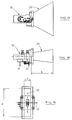
- FIG. 1 is a schematic view of the microwave part of a detector of the aforementioned type: a distinction is made between the transceiver module 10 and a horn antenna 20.
- FIG. 2 is a similar view after rotation of the assembly of 90 ° around its longitudinal axis.
- Figure 3 shows a front view of the assembly.
- the transmission-reception module consists for example (FIG. 2) of a resonant cavity in which a correctly supplied Gunn diode 11 generates a microwave signal which is radiated in space by the antenna 20.
- the module works for example at a frequency of 24.125 GHz (K band). It goes without saying that the following description is valid for other frequencies. Only the dimensions of the various constituent elements of this microwave part are dependent on the frequency of the transceiver.
- the horn of the antenna 20 radiates in the two planes containing its axes of symmetry 21 and 22.
- any relative moving obstacle in the field of action of the detector reflects part of the incident wave and the wave thus reflected is found picked up by the antenna 20 and mixed with the incident wave thanks to a Schottky diode 12 correctly placed in the portion of waveguide located between the resonant cavity comprising the Gunn diode 11 and the antenna 20. Consequently, and in due to the Doppler effect, a low frequency signal is available at the terminals of the Schottky diode 12.
- the frequency of the Doppler signal is proportional to the relative speed of the detected obstacle and its amplitude is proportional to the size and proximity of the detected obstacle.
- the signal at the terminals of the Schottky diode 12 is a noise signal of practically zero amplitude.
- the Doppler signal available at the terminals of the Schottky diode 12 is injected into an electronic detection circuit (not shown) capable of producing an active signal to control the automation which controls an automatic device , for example an automatic door, when a person or a moving object has been detected in the detection field.
- an electronic detection circuit capable of producing an active signal to control the automation which controls an automatic device , for example an automatic door, when a person or a moving object has been detected in the detection field.
- the Doppler effect microwave motion detector intended in this case to provide a detection signal to the automatic door for example, is placed at the top of the latter and emits the microwave signal from top to bottom at an angle. determined.
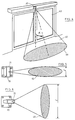
- FIG. 4 shows the detection lobe of a detector 30 associated with a sliding automatic door 40. It is in the form of an oblique cone 50 whose base 60, hatched at ground level, is of ellipsoidal shape. The axis of this cone forms with the vertical a determined angle ⁇ .
- the shape and size of the detection lobe are imposed by the dimensions of the antenna and by the sensitivity of the electronic detection circuit.
- Figures 5 and 6 illustrate detection lobes 60 emitted by a horn antenna.
- the radiation characteristics of a horn antenna are such that, the closer the opposite walls 70 and 71 of the antenna, the greater the width 1 of the corresponding lobe 60, and vice versa.
- it is simple, from a single antenna of rectangular section, to generate a narrow and deep detection lobe 60 (as illustrated in FIG. 5) or on the contrary, a detection lobe 60 wide and not very deep (as illustrated in Figure 6). To do this, it suffices to cause the microwave portion of the detector, or even the detector itself, to rotate through 90 °, so as to present the antenna with its opposite walls 70 and 71 close together. develop a large lobe 60 (FIG. 6) or with its opposite walls 70 and 71 spaced apart from one another to develop a narrow lobe 60 (FIG. 5).
- the detector is placed at a height of 2.20 m above the ground.
- Figure 7 corresponds to the case where the antenna is present with its opposite walls 70 and 71 distant from each other, which allows it to develop a narrow lobe, for example 2.20 m wide and 3 m deep.
- FIG. 8 corresponds to the case where the antenna is presented with its opposite walls 70 and 71 close to each other, which allows it to develop a wide lobe, for example 3.40 m wide and 1 , 60 m deep.
- the dimensional considerations relating to the detection lobes developed by the Doppler effect microwave motion detectors also apply to microwave detectors capable of detecting, in addition to motion, the presence of people or immobile objects in their detection field.
- the signal processing is fundamentally different from the Doppler signal processing described above, but what has been said concerning the lobes developed by the horn antennas remains valid in this case of application.
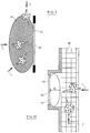
- the detection process involves any person or any moving object being detected regardless of its angle of approach relative to the detector, as illustrated in Figure 9, where there is a cross-sectional view of an automatic door sliding 40, equipped with a detector 30 developing a detection lobe 60.
- Pedestrian 1 approaching the door perpendicularly, is detected as well as pedestrian 2 which moves parallel to the door, and that pedestrian 3 which approaches the door obliquely .
- this detection mode is very appropriate and leads to an effective opening of the door.
- FIG. 10 illustrates the case of incessant traffic of pedestrians in front of a detector 30.
- the passage of pedestrians such as 2, wandering along the sidewalk without intending to pass through the door, should not cause the opening thereof , while pedestrians such as 1 should be detected.
- One solution to this problem consists in implementing a detector 30 developing a wide lobe 60 but of reduced depth and generally included in the space separating the door from the pavement itself.
- a better solution would be to provide the detector with an additional function making it insensitive to any movement parallel to the plane of the door, but this would increase the costs.
- the detector 30 is fixed to the upper part of a leaf 40 and it directs its detection lobe 60 from top to bottom.
- the detection process must cause the revolving door to slow down or even stop when a person moves in it at a speed below the tangential speed of the leaf, and is about to be caught and struck by the leaf it precedes, with consequences that can be damaging.
- the detector attached to each leaf, accompanies it in its rotational movement, it is desirable that the depth of the detection lobe, measured at ground level, which is relatively reduced.
- a case very similar to the previous one is that of microwave detectors intended to protect people in front of or behind the movable leaf of a pivoting door, as illustrated in FIGS. 13 and 14.
- the detector 30 is fixed to the upper part of the leaf 40 and it directs its detection lobe 60 from top to bottom.
- the detection process must slow down or even stop the pivoting door when a person moves nearby while the leaf is in motion and likely to strike the person with damaging consequences.
- the detector fixed to the movable leaf, accompanies the latter in its rotational movement, it is desirable that the depth of the detection lobe, measured at ground level, be relatively reduced in order not to detect insignificant obstacles.
- the detector 30 developing a deeper detection lobe, such as 61 would cause the unwanted detection of a wall 100 while the door is still in the opening phase, or, for a detector 31 located on the other side of the door, and also developing a deeper lobe, such as 61, the unwanted detection of a fixed amount of the door such as 101.
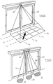
- a rolling shutter or sectional door is in the form of a shutter, consisting of sections hinged to each other, moving vertically by translation in lateral guides, and winding at its upper part at the like a shutter, as illustrated in figure 15.
- the dangerous part of this kind of door is the lower edge of it. During the downward movement of the door, its lower edge can strike and possibly injure a person parking below. Similarly, an object left in the range of the door can be damaged by it.
- the protection of this dangerous zone can be achieved by a detector 30 fixed under the edge of the rolling shutter holder 40 and directing its detection lobe 60 from top to bottom.
- the detection process must slow down or even stop the roller shutter in the event of danger.
- the detector fixed to the mobile door, accompanies the latter in its translational movement, it is desirable that the depth of the detection lobe, measured at ground level, be relatively reduced, in order not to detect insignificant obstacles .
- the detector 30 developing a deeper detection lobe, such as 61 would for example result in the unwanted detection of objects or vehicles present near the door, without risk for these to be struck, and would cause an untimely and unjustified stop of the door.
- the horn antenna technology partially solves the problem of detection in a shallow lobe. Indeed, the dimensions of the detection lobe strongly depend on the ratio of the dimensions of the rectangular section of the horn antenna. In addition, the more distant the opposite walls, the narrower the corresponding lobe, and vice versa.
- the transceiver module 10 works, for example, at a frequency of 24,125 GHz.
- the gain of said antenna is of the order of 13 dB.
- FIG. 20 corresponds to the case where the antenna is presented with its opposite walls 70 and 71 distant from each other, which allows it to develop a narrow lobe, 1 m wide for example, and a depth 3 m for example.
- FIG. 21 corresponds to the case where the antenna presents itself with its opposite walls 70 and 71 close to one another, which allows it to develop a wide lobe, 3.4 m wide for example and 1 m deep.
- the lobe is hardly less deep than 1 m. This makes this solution valid, within certain limits, for solving the case of detection along a sidewalk or a shopping mall, which preferably requires a very shallow detection lobe. On the other hand, this solution would not apply satisfactorily to the examples illustrated by FIGS. 11 to 16. A lobe 1 m deep would undoubtedly cause untimely detections. On the other hand, it does not allow the discrimination of the direction and the direction of movement of the detected mobiles. As a result, this practical limitation of the horn antenna technology to lobes having dimensions of not less than 1 m in depth makes the use of conventional microwave detectors unsuitable in many cases.
- microwave presence detectors fitted with horn antennas As mentioned above, the above also applies to microwave presence detectors fitted with horn antennas.
- Active infrared detection technology proceeds by emitting infrared radiation into a detection lobe and by measuring the diffuse radiation reflected by the environment or by any obstacle to be detected.
- Detectors based on this technology sometimes have the advantage of detecting the presence of people or stationary objects. Equipped with correctly sized cylindrical Fresnel lenses, this type of detector makes it possible to detect the presence and movement of a person or an object in a detection lobe generally wide, but of very reduced depth, for example less than 30 cm, and constituting a detection or protection curtain.
- a known variant of the active infrared detection technique makes it possible to provide the detector with a function for taking into account the approach angle of the mobile in the detection field. This is an advantage in the situation illustrated in Figure 10, where pedestrians traveling along the sidewalk (therefore parallel to the plane of the door) without intending to enter, should not be detected.
- This technique involves emitting radiation infrared in a matrix network of discrete transmitters, for example three rows of four columns, denoted L1, L2, L3 and C1 to C4 in FIG. 22.
- the detector 30 is then placed for example in front of a sliding automatic door 40.
- the transmitters are successively made active by horizontal scanning, L1-C1, L1-C2, ..., L3-C4, while the radiation is reflected by the environment in a matrix network of discrete receivers synchronized on the corresponding transmitters.
- Signal processing similar to image processing, makes it possible to extract information on the direction and direction of movement of the detected mobile, represented by the arrow in FIG. 22. This processing is however relatively complex and the detectors based on this technique are expensive. In addition, there are affected by the imperfections inherent in active infrared technology.
- Ultrasonic detectors have certain drawbacks, in particular undesirable detections due to the modification of the sensitivity of the detector as a function of climatic conditions (temperature, humidity), sensitivity to drafts, sensitivity to vibrations and mechanical noise, absence of detection for non-orthogonal targets or covered with absorbent materials such as wool or fabric, these situations being common in the environment of an automatic door.
- the detection lobe 60 at ground level of such a detector is generally circular with a fairly reduced diameter of the order of 50 cm, as illustrated in FIG. 23.
- a multiple detector 30 is then mounted above the automatic door 40, and it directs its ultrasonic beams 50 from top to bottom.
- the small size of a lobe is favorable to the application cases illustrated in FIGS. 10 to 16 with regard to the depth of the lobes, but it is unsuitable with regard to the width of the lobe, which is circular. It is therefore necessary, in most cases, to use several detectors simultaneously, as illustrated in Figure 23, in order to extend the side coverage. This obviously increases the price of the installation. In addition, the technique hardly lends itself to taking into account the angular component of the movement of the detected mobile.
- An exemplary embodiment of an elongated radiating antenna is constituted by a waveguide antenna with radiating slits as illustrated for example in FIG. 24.
- This antenna consists of a guide of rectangular waves 110.
- the dimensions a and b thereof are a function of the frequency of the transmitted wave, and one of the faces 111, generally the narrowest, is pierced with equidistant slots 120, through which electromagnetic energy is radiated.
- the wave transmitted in the guide and radiated by the slots 120 is generated at one end of the wave guide by an appropriate transmitter (not shown in Figure 24).
- the slots 120 are regularly spaced apart by a distance equal to ⁇ g / 2, where ⁇ g is the wavelength of the wave transmitted in the waveguide.
- the slots are inclined alternately by an angle ⁇ in one direction and in the opposite direction, so that all the slots radiate in phase.
- slots 120 inclined in the short side of the guide 111 interrupts the surface currents 130 arising in the walls of the guide following the propagation of the wave in the guide. This generates a transverse electromagnetic field, the propagation of which takes place in a preferred direction 140 perpendicular to the short side of the waveguide.
- the wavelength in the guide is 15.303 mm, which corresponds to a spacing between the slots of 7.65 mm.
- one end of the waveguide is supplied by a transceiver 10, located at a distance equal to ⁇ g of the first slot and the operating principle of which has been described previously and illustrated in FIGS. 1 to 3.
- the other end ends on a suitable load 150, consisting for example of an absorbent located at 3. ⁇ g / 4 from the last slot.
- the adaptation of the terminal load ensures a distribution of the radiated power along the guide as uniform as possible.
- Other embodiments of the adapted terminal load are possible. The same applies to any variant according to which the radiating slots are formed in the long side of the waveguide.
- a suitable load has already been used at the end of a waveguide (see EP-A-0109552) but it was a waveguide on which antennas were fixed at regular intervals and not of 'a slotted waveguide.
- FIG. 27 represents, in relative scale, the distribution of power P along an antenna 1.50 m long, with the number N of slots, for example ninety slots, represented on the abscissa. It can be seen that the suitable load makes it possible to obtain a lobe of very good longitudinal uniformity. As a result, a first condition allowing the application of antennae in slot guides to detectors developing wide and shallow detection lobes is carried out. In fact, it has appeared from the applications illustrated in FIGS. 11 to 16, that the lobe developed by the detector must be as uniform as possible in the width direction, that is to say parallel to the plane of the automatic door.
- the first n 1 slots can for example have an inclination ⁇ 1
- the following n 2 slots have an inclination ⁇ 2 , with ⁇ 2 > ⁇ 1 , and so on, so as to standardize the power along the antenna.
- the second condition to be fulfilled by the antenna in slotted waveguide is to develop a very narrow angular opening lobe, in a plane perpendicular to the axis of the guide.
- Figure 28 shows the polar radiation diagram of the antenna illustrated in Figures 25 and 26.
- the slot waveguide antenna is assumed to be perpendicular to the plane of the diagram, at the origin of the coordinates, with radiating slots down. It can be seen from the measurements made that the antenna radiates in an almost isotropic manner, which makes the production of a narrow lobe impossible. Indeed, the conventional aperture at -3 dB of the measured radiation lobe is 2 x 30 °. Under these conditions, and according to the sensitivity of the detector, the theoretical depth of the lobe of detection for a detection height of 2 m could reach a value of 2 m.
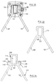
- reflectors are for example in the form of metal plates 160 and 161, integral with the long sides of the waveguide, as illustrated in FIGS. 29 and 30, and form between them an angle ⁇ encompassing the short side 111 of the guide d 'waves pierced with slits.
- the metallic reflectors 160 and 161 can be made from copper or brass plates folded so as to form the angle ⁇ between them, and be welded on the long sides of the waveguide 110.
- FIG. 30 shows a side view of the slot-wave antenna represented in FIGS. 25 and 26, but provided with the above-mentioned reflectors 160, 161. These have an opening angle ⁇ of 53.4 ° for example and their width C is 30 mm. Thanks to these reflectors, which practically play the role of the opposite walls 70, 71 of the horn antenna illustrated in FIGS. 5 and 6, the angular opening of the lobe, in a plane perpendicular to the axis of the guide, is greatly reduced. as shown in the polar radiation diagram of FIG. 31. It can be seen there that the conventional opening at -3 dB of the measured radiation lobe is reduced to 2 x 10 °. Under these conditions, and depending on the sensitivity of the detector, the theoretical depth of the detection lobe for a detection height of 2 m is less than 0.50 m, which corresponds well to the desired objectives for the applications illustrated in Figures 11 to 16 .
- Another embodiment and fixing of reflectors consists in fixing the metal plates on either side of the waveguide using the clamping system illustrated in FIG. 32.
- a U-shaped section, denoted 170 clamps the two parts reflectors 160 and 161 against the long sides of the waveguide 110.
- the fixing is carried out, for example, by pressure screws 180, distributed regularly along the waveguide.
- a conductive sticker such as 190, or any other conventional means such as glue or conductive paste.
- the waveguide 110 and the reflectors 160 and 161 are formed in a single piece of extruded aluminum for example.
- the slots 120 are produced, for example, by cutting using a special tool, or by machining.
- the part 200 corresponds to the waveguide 110 proper, while the part 210 corresponds to the reflectors 160, 161. Being semi-open, the profile 210 lends itself more easily to the cutting of the slots 120 , not shown in the figure.
- the two parts 200 and 210 of this embodiment are fixed to each other for example by means of self-drilling screws 220 arranged regularly along the waveguide and screwed in fixing flanges 230. Electrical continuity can be ensured by the aforementioned means 190, such as conductive adhesive tape, glue or conductive paste.
- the fixing flanges 230 have been shown at the level of the plane containing the slots 120. These flanges 230 may be located at any level along the long sides of the waveguide 110.
- Other methods of fixing of the two parts 200 and 210 of the antenna extruded into a slot waveguide for example welding, bonding, crimping, grooving) are to be considered as part of the invention.
- a particularly advantageous embodiment of the slotted waveguide antenna provided with reflectors consists in making this device in two parts arranged as described below and with reference to FIG. 35.
- the first part, denoted 250 is consisting of a semi-open extruded aluminum profile, the bottom 110 of which plays the role of a waveguide part and the sides 160 and 161 of which play the role of reflectors. Note that two grooves 251 and 252 facing each other are formed along the internal part of the profile.
- the second part, denoted 260 consists of a metal tongue inserted in the two grooves 251 and 252.
- This tongue plays the role of the radiating face 111 of the waveguide thus closed, provided that the grooves (not drawn) be provided, as mentioned above.
- This solution has the advantage of simplifying the machining of the slots in the tongue 260, insofar as this operation can be carried out before its insertion into the profile, which ensures optimum accessibility to the tooling of cut slits. It is clear that, in this embodiment, the slots will have a length substantially less than the width l of the tongue. It has been shown that this does not affect the characteristics of the radiated field.
- the tongue 260 can be made from a metallic flat in copper or in extruded aluminum, for example.
- a particularly advantageous solution consists in using an epoxy substrate covered with a copper metallization, as commonly used in the manufacture of printed circuits. In this case, the production of the radiating slits can be done by photoengraving, a process particularly easy to implement, and which leads to a precise and inexpensive solution.
- this variation can be achieved by threading successive tongues in the grooves 251 and 252 carrying slots having a different angle ⁇ .
- the detector housing the main part of the waveguide and the reflectors: this is illustrated in the figure 36.
- the housing of the detector using the antenna in slotted waveguide is designated at 270, the main part of the waveguide is denoted 110 and the reflectors are denoted 160 and 161.
- the face radiating from the waveguide consists of a tongue 260 inserted in the grooves 251, 252, said face being pierced with slots, not shown in the drawing.
- the housing 270 thus formed may contain other members necessary for the operation of the detector, such as for example a printed circuit 280, inserted in longitudinal grooves 281 and 282.
- the motion or microwave presence detector is equipped with a slotted waveguide antenna, which is correctly dimensioned and provided with an appropriate terminal load in order to make the radiated power as constant as possible parallel to the axis of the guide, and which is provided with reflectors arranged so as to limit the angular opening of the radiated lobe.
- FIG. 37 illustrates the case of an automatic transport vehicle 240, for example a wire-guided cart.
- the vehicle is equipped with a detector 30 provided with a slot wave antenna as described above. Thanks to the detector, on the one hand, the width of the detection lobe 60 can be adapted to the width of the vehicle and is proportional to the length of the waveguide used and, on the other hand, the depth of the lobe projected in front of the vehicle. is sufficiently reduced, thanks to the reflectors used, to avoid premature detections, in particular when the vehicle changes direction.
- the main direction of radiation indicated by the arrow 140 in FIG. 24, is perpendicular to the short side of the waveguide, and therefore perpendicular to the detector itself.
- transverse components also exist, but their amplitude is far less than the amplitude of component 140 of the electromagnetic field.
- the invention makes it possible to produce a microwave motion detector having a preferred direction of detection.
- FIG. 38 represents a detector 30 arranged on a sliding automatic door 40.
- This detector develops a detection lobe denoted 60 at ground level. It follows from the above that only the mobiles with a speed component perpendicular to the detector can be detected in this way, that is to say in the directions noted 140.
- Pedestrian 1 who approaches the door practically perpendicular to that -this will be detected while pedestrian 2, which moves parallel to the door, will not be detected. However, if during its movement, the pedestrian 2 bends its trajectory towards the door, it generates a speed component towards the detector and it will be detected.
- This selective behavior of the detector is highly desirable when the detector is installed for example on a door near a sidewalk or a shopping mall. In this case, the detection of parallel traffic constitutes a nuisance, since pedestrians who wander parallel to the door generally do not intend to enter it.
- the detector can also use antennas which are functionally equivalent to those illustrated in FIGS. 25 and 26.
- This is in particular the case of an antenna in which a transistor oscillator Field effect (FET) driven by a dielectric resonator (DRO) is used in place of the transceiver 10 described above.
- FET transistor oscillator Field effect
- DRO dielectric resonator
- flat microstrip antennas comprising a certain number of interconnected radiating elements, the dimensions and spacings of which allow the radiation of lobes similar to those which are radiated by the antenna in waveguide with slits described. upper.
- This parallel traffic detection system consists in using a unidirectional transceiver, known per se, instead of the transceiver 10 illustrated in FIGS. 25 and 26.
- This unidirectional transceiver is constituted for example a resonant cavity, a Gunn diode for the generation of the electromagnetic wave, and two Schottky diodes, phase shifted by a fraction of wavelength and constituting two measurement channels.
- the two signals provided by the two Schottky diodes are analyzed by a discriminator circuit which, depending on the phase shift of the signals, makes it possible to distinguish the moving object which is approaching from the moving element which moves away. The use of detectors sensitive only to approach movements is thus possible.
- FIGS. 25 and 26 it is also possible to use a one-channel transceiver as illustrated in FIGS. 25 and 26, and to constitute the second channel measurement from a passive cavity fixed in place of the terminal load and supporting a Schottky diode.
- This passive cavity has, for example, the dimensions of the cavity 10 illustrated in Figures 1 to 3 but does not include a Gunn diode.
- Another way of making this alternative embodiment is to use the antenna as a slotted waveguide as shown in FIGS. 25 and 26, and to install the second Schottky diode in the waveguide itself , between the last slot and the terminal load.
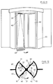
- the detection device can be used in a doubly advantageous manner on the movable leaves 40 of a drum holder, as illustrated in FIG. 39.
- the depth P of the lobe 60 is reduced.
- the detector 30 is insensitive to lateral traffic, that is to say parallel to the plane of the leaf 40. This is favorable insofar as a pedestrian 250, when he enters an open sector of the door, is driven by a speed of movement whose main component 251 is parallel to the plane of the door. However, it is precisely desirable to avoid detection in this initial phase of the pedestrian's progress.
- the detector is arranged on the movable part or parts of the automatic door, or on board a vehicle. Whether it is a motion detector or a presence detector, a microwave detector moving with a moving object sees its environment change in relation to itself during its movement. Everything happens as if the detector were fixed and the environment was in relative motion. Under these conditions, the useful signal delivered by the detector, either the Doppler signal or a signal proportional to the reflected power, varies continuously depending on the environment. Consequently, it is impossible to set a detection threshold representative of an obstacle.
- a first example of application of the method according to the invention relates to the protection in the environment of the rolling shutter door illustrated in FIGS. 15 and 16.
- the dangerous movement with this type of door is the descent, which implies a risk of collision with a person or an object.
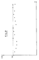
- the lower edge of the shutter holder 40 is equipped with a Doppler effect motion detector 30, for example provided with an antenna having a length sufficient to ensure good coverage in width. If the evolution of the signal supplied by this detector during the movement of the door is recorded, between the high position (open) and the low position (closed) and in the absence of an obstacle in the detection field, a detection signal shown in FIG. 40 is obtained.
- this signal is of increasing amplitude A (V), and corresponds to the relative approach of the environment with respect to the detector, first far (left part of the curve) and then closer and closer (right part of the curve).
- the abscissa is graduated in time (from 0 to 30 seconds).
- a second scale proportional to the height of the lower edge of the door relative to the ground, is also indicated (from 4 m to 0 m).
- This method consists in permanently measuring the useful signal supplied by the detector, for example a microwave detector with Doppler effect with a slot waveguide antenna, and in comparing the value measured, at a given instant, with the corresponding value. of the reference curve, previously memorized. Any distortion from the reference curve indicates the presence of an obstacle, this information can be exploited to ensure safety in the door environment. It is therefore useful, according to the invention, for the signal processing system supplied by the detector to carry out a learning cycle of its environment beforehand. For this reason, it is convenient to architect the signal processing and decision-making system around a microprocessor.
- the microprocessor acquires and stores the useful signal as a function of time, ie depending on the position of the door and in the absence of any obstacle in its environment.
- the stored signal has, for example, the shape of the signal illustrated in FIG. 40. If the speed of descent of the door is not sufficiently constant, a position sensor, known per se, can be used in order to clock the acquisition of measurements. If necessary, the gain of the signal amplification chain can be made variable according to the position of the detector relative to the environment so as to make the reference curve practically constant.
- the microprocessor compares the value measured at a given instant - therefore for a determined position of the door - with the corresponding value of the reference curve. If a distortion appears between these two values, this means that the detector has detected the presence of an obstacle, and the decision process results, for example, in stopping the door, or raising it.
- Figure 41 shows how an aluminum plate, inserted into and then removed from the detection field of the detector protecting the rolling shutter door described above, affects the measured curve. It is observed that the aluminum plate is already detected while the door is at a height of approximately 3.50 m above the ground. This is due to the high reflectivity of the plate.
- Figure 42 shows how this same detector detects a hand inserted and removed from the detection field at a height of one meter above the ground. It appears that the hand is detected while the door is at a height of about 1.50 m above the ground.
- a second example of application of the method according to the invention relates to the protection in front of the leaves of a revolving door, as shown in FIGS. 11 and 12.
- the microprocessor proceeds to the acquisition and storage of the useful signal as a function of time, that is to say as a function of the angular position of the door and in the absence of an obstacle in its environment.
- the stored signal has, for example, the appearance of signal A illustrated in FIG. 43.
- a position sensor known per se, can be used in order to clock acquisition of measurements.
- the ordinate axis is reversed, and has its origin at level 5.
- the microprocessor compares the value measured at a given instant - therefore for a determined angular position of the gate - with the corresponding value of the reference curve. If a distortion appears between these two values, this means that the detector has detected the presence of an obstacle, and the decision process results, for example, in slowing down or stopping the door. This kind of distortion appears clearly on curve B of FIG. 43, which corresponds to the presence of a hand inserted into and then removed from the detection field of the detector.
- the reference curve designated by A in FIG. 43 can, depending on the speed of rotation of the door, be shifted proportionally towards the positive or negative ordinates. This is due to the bandwidth of the signal amplification chain. It is advantageous to take advantage of this characteristic which is a function of the speed of rotation and which can be previously memorized. Indeed, in the case of the drum holder which can operate with several rotational speeds, the prior memorization of the reference waves at several speeds makes it possible on the one hand to detect an obstacle with more precision, and on the other hand, adopt an action on the door depending on the speed: more or less vigorous braking during a detection.
- the method according to the invention is not limited to the processing of the signal supplied by a Doppler effect microwave motion detector, provided with an antenna as mentioned above. It can advantageously be used in the context of measurements carried out with other types of detectors, such as for example active infrared detectors.
- the measured and stored reference signal corresponds to the reflection of infrared radiation by the environment, in the absence of an obstacle.
Landscapes
- Engineering & Computer Science (AREA)
- Radar, Positioning & Navigation (AREA)
- Remote Sensing (AREA)
- Computer Networks & Wireless Communication (AREA)
- Physics & Mathematics (AREA)
- General Physics & Mathematics (AREA)
- Radar Systems Or Details Thereof (AREA)
- Burglar Alarm Systems (AREA)
- Geophysics And Detection Of Objects (AREA)
Applications Claiming Priority (3)
| Application Number | Priority Date | Filing Date | Title |
|---|---|---|---|
| BE9200596 | 1992-06-25 | ||
| BE9200596A BE1005991A3 (fr) | 1992-06-25 | 1992-06-25 | Dispositif et procede de detection et de protection. |
| EP93912484A EP0647324B1 (de) | 1992-06-25 | 1993-06-25 | Verfahren und vorrichtung zum auffinden und schützen von personen und objekten |
Related Parent Applications (2)
| Application Number | Title | Priority Date | Filing Date |
|---|---|---|---|
| EP93912484A Division EP0647324B1 (de) | 1992-06-25 | 1993-06-25 | Verfahren und vorrichtung zum auffinden und schützen von personen und objekten |
| EP93912484.8 Division | 1994-01-06 |
Publications (3)
| Publication Number | Publication Date |
|---|---|
| EP0768541A2 true EP0768541A2 (de) | 1997-04-16 |
| EP0768541A3 EP0768541A3 (de) | 1997-05-21 |
| EP0768541B1 EP0768541B1 (de) | 1999-09-29 |
Family
ID=3886338
Family Applications (2)
| Application Number | Title | Priority Date | Filing Date |
|---|---|---|---|
| EP96203438A Expired - Lifetime EP0768541B1 (de) | 1992-06-25 | 1993-06-25 | Verfahren und Vorrichtung zum Auffinden und Schützen von Personen und Objekten |
| EP93912484A Expired - Lifetime EP0647324B1 (de) | 1992-06-25 | 1993-06-25 | Verfahren und vorrichtung zum auffinden und schützen von personen und objekten |
Family Applications After (1)
| Application Number | Title | Priority Date | Filing Date |
|---|---|---|---|
| EP93912484A Expired - Lifetime EP0647324B1 (de) | 1992-06-25 | 1993-06-25 | Verfahren und vorrichtung zum auffinden und schützen von personen und objekten |
Country Status (6)
| Country | Link |
|---|---|
| US (1) | US6114956A (de) |
| EP (2) | EP0768541B1 (de) |
| AT (2) | ATE185199T1 (de) |
| BE (1) | BE1005991A3 (de) |
| DE (2) | DE69326626T2 (de) |
| WO (1) | WO1994000777A1 (de) |
Cited By (1)
| Publication number | Priority date | Publication date | Assignee | Title |
|---|---|---|---|---|
| FR3091525A1 (fr) | 2019-01-04 | 2020-07-10 | Balyo | Équipement de manutention autoguidé comportant un moyen de détection |
Families Citing this family (29)
| Publication number | Priority date | Publication date | Assignee | Title |
|---|---|---|---|---|
| US6177903B1 (en) | 1999-06-14 | 2001-01-23 | Time Domain Corporation | System and method for intrusion detection using a time domain radar array |
| US7649925B2 (en) * | 1999-06-14 | 2010-01-19 | Time Domain Corporation | Time transfer utilizing ultra wideband signals |
| US7592944B2 (en) * | 1999-06-14 | 2009-09-22 | Time Domain Corporation | System and method for intrusion detection using a time domain radar array |
| US6683296B2 (en) * | 2001-09-13 | 2004-01-27 | Miller Edge, Inc. | Sensor system for controlling movement of a door using a time-delay failure signal |
| US6885300B1 (en) * | 2002-06-05 | 2005-04-26 | The Watt Stopper, Inc. | Broad field motion detector |
| SE524205E (sv) * | 2002-09-12 | 2005-12-06 | Radio Components Sweden Ab | Ett förfarande för att tillverka antennelement |
| RU2269142C2 (ru) * | 2004-03-10 | 2006-01-27 | Открытое акционерное общество "Протон+Сервис" | Способ обнаружения по критерию отношения правдоподобия пачечного сигнала с огибающей известной формы и устройство его осуществления |
| DE102004053821B4 (de) | 2004-11-04 | 2008-12-18 | Dorma Gmbh + Co. Kg | Türanlage mit automatisch verfahrbaren Flügeln sowie ein Verfahren zum Betrieb derartiger Türanlagen |
| ES2572772T3 (es) * | 2005-01-21 | 2016-06-02 | Bea S.A. | Sensor para utilizar en puertas automáticas |
| US7551080B2 (en) * | 2006-07-17 | 2009-06-23 | Sensormatic Electronics Corporation | Control for embedded and door-mounted antennas |
| RU2382381C2 (ru) * | 2007-11-12 | 2010-02-20 | Анатолий Андреевич Косин | Способ локальной пачечной обработки принимаемых рлс сигналов и устройство его осуществления |
| US8169356B2 (en) * | 2007-12-31 | 2012-05-01 | Honeywell International Inc. | Anti-mask motion sensor |
| US8791839B2 (en) * | 2008-06-05 | 2014-07-29 | Wabtec Holding Corp. | Ultrasonic passenger detection |
| FR2936891B1 (fr) * | 2008-10-07 | 2013-03-15 | Bubendorff | Dispositif de detection de la presence d'un objet ou d'un etre vivant |
| DE102010037397A1 (de) * | 2010-09-08 | 2012-03-08 | Miele & Cie. Kg | Haushaltgerät, insbesondere grifflose Geschirrspülmaschine |
| BE1022617B1 (nl) * | 2014-10-27 | 2016-06-16 | Dynaco Europe Nv | Intelligente "auto-close"-deur |
| JP2017002542A (ja) * | 2015-06-09 | 2017-01-05 | アズビル株式会社 | 自動ドア制御装置および自動ドア制御方法 |
| US10816658B2 (en) | 2016-09-07 | 2020-10-27 | OmniPreSense Corporation | Radar enabled weapon detection system |
| JP6827216B2 (ja) * | 2017-02-28 | 2021-02-10 | パナソニックIpマネジメント株式会社 | 検知装置、及び制御システム |
| US10221610B2 (en) | 2017-05-15 | 2019-03-05 | Otis Elevator Company | Depth sensor for automatic doors |
| US10386460B2 (en) | 2017-05-15 | 2019-08-20 | Otis Elevator Company | Self-calibrating sensor for elevator and automatic door systems |
| FR3069009B1 (fr) * | 2017-07-13 | 2020-09-18 | Somfy Activites Sa | Dispositif radiofrequence pour une installation domotique de fermeture ou de protection et installation domotique associee |
| DE102019122612A1 (de) * | 2019-08-22 | 2021-02-25 | Selux Ag | Radarbewegungsmelder |
| CN110672045B (zh) * | 2019-10-18 | 2025-03-14 | 贵州民族大学 | 一种结构形变检测传感器及检测系统与检测方法 |
| JP7369025B2 (ja) * | 2019-12-18 | 2023-10-25 | 三和シヤッター工業株式会社 | 検知装置 |
| EP4043687A1 (de) * | 2021-02-12 | 2022-08-17 | dormakaba Deutschland GmbH | Verfahren zum betrieb eines türbetätigers |
| US12247433B2 (en) * | 2021-10-14 | 2025-03-11 | BEA Inc. | Infrared curtain systems and methods |
| WO2026133567A1 (ja) * | 2024-12-20 | 2026-06-25 | オプテックス株式会社 | 電波センサ |
| EP4772712A1 (de) * | 2025-01-07 | 2026-07-08 | dormakaba Deutschland GmbH | Verfahren zum automatischen öffnen einer tür, automatische tür, entsprechendes computerprogrammprodukt |
Citations (3)
| Publication number | Priority date | Publication date | Assignee | Title |
|---|---|---|---|---|
| FR2160274A1 (de) | 1971-11-17 | 1973-06-29 | Pont A Mousson Fond | |
| EP0109552A1 (de) | 1982-10-22 | 1984-05-30 | Siemens Aktiengesellschaft | Mikrowellen-Einbruchmeldesystem |
| EP0440126A1 (de) | 1990-01-29 | 1991-08-07 | Alcatel Espace | Antenne mit geschlitzten Hohlleitern, insbesondere für Weltraumradar |
Family Cites Families (13)
| Publication number | Priority date | Publication date | Assignee | Title |
|---|---|---|---|---|
| DE2002012A1 (de) * | 1969-01-21 | 1970-08-13 | Del Signore Dr Giovanni | Vorrichtung und Verfahren zum Melden von Hindernissen und zur Anzeige der Entfernung der Hindernisse |
| GB1402419A (en) * | 1971-11-02 | 1975-08-06 | Microwave & Electronic Syst | Target detection system |
| US4009476A (en) * | 1975-06-27 | 1977-02-22 | Solfan Security Systems | Apparatus for automatically controlling door operation |
| US4197537A (en) * | 1976-08-19 | 1980-04-08 | Honeywell Inc. | Intruder detection system |
| DE3422228A1 (de) * | 1984-06-15 | 1985-12-19 | Dorma-Baubeschlag Gmbh & Co Kg, 5828 Ennepetal | Steuereinrichtung fuer eine selbsttaetig bewegbare drehfluegeltuer |
| US4815046A (en) * | 1985-04-29 | 1989-03-21 | Xecutek Corporation | Ultrasonic sensor system |
| US4779240A (en) * | 1985-04-29 | 1988-10-18 | Xecutek Corporation | Ultrasonic sensor system |
| GB8527277D0 (en) * | 1985-11-06 | 1985-12-11 | Formula Systems Ltd | Proximity detector |
| US4991146A (en) * | 1989-11-30 | 1991-02-05 | Deere & Company | Intrusion detection system |
| US5150099A (en) * | 1990-07-19 | 1992-09-22 | Lienau Richard M | Home security system and methodology for implementing the same |
| US5196826A (en) * | 1991-06-26 | 1993-03-23 | C & K Systems, Inc. | Sensor for detecting the passage of a person or an animal in a field of view |
| BE1005734A5 (fr) * | 1992-04-29 | 1994-01-11 | Icoms Sprl | Procede et systeme de detection. |
| US5481266A (en) * | 1994-11-17 | 1996-01-02 | Davis; Warren F. | Autodyne motion sensor |
-
1992
- 1992-06-25 BE BE9200596A patent/BE1005991A3/fr not_active IP Right Cessation
-
1993
- 1993-06-25 DE DE69326626T patent/DE69326626T2/de not_active Expired - Fee Related
- 1993-06-25 AT AT96203438T patent/ATE185199T1/de not_active IP Right Cessation
- 1993-06-25 WO PCT/BE1993/000042 patent/WO1994000777A1/fr not_active Ceased
- 1993-06-25 EP EP96203438A patent/EP0768541B1/de not_active Expired - Lifetime
- 1993-06-25 AT AT93912484T patent/ATE159820T1/de not_active IP Right Cessation
- 1993-06-25 US US08/351,480 patent/US6114956A/en not_active Expired - Fee Related
- 1993-06-25 DE DE69314953T patent/DE69314953T2/de not_active Expired - Fee Related
- 1993-06-25 EP EP93912484A patent/EP0647324B1/de not_active Expired - Lifetime
Patent Citations (3)
| Publication number | Priority date | Publication date | Assignee | Title |
|---|---|---|---|---|
| FR2160274A1 (de) | 1971-11-17 | 1973-06-29 | Pont A Mousson Fond | |
| EP0109552A1 (de) | 1982-10-22 | 1984-05-30 | Siemens Aktiengesellschaft | Mikrowellen-Einbruchmeldesystem |
| EP0440126A1 (de) | 1990-01-29 | 1991-08-07 | Alcatel Espace | Antenne mit geschlitzten Hohlleitern, insbesondere für Weltraumradar |
Cited By (1)
| Publication number | Priority date | Publication date | Assignee | Title |
|---|---|---|---|---|
| FR3091525A1 (fr) | 2019-01-04 | 2020-07-10 | Balyo | Équipement de manutention autoguidé comportant un moyen de détection |
Also Published As
| Publication number | Publication date |
|---|---|
| DE69314953D1 (de) | 1997-12-04 |
| US6114956A (en) | 2000-09-05 |
| WO1994000777A1 (fr) | 1994-01-06 |
| ATE185199T1 (de) | 1999-10-15 |
| EP0768541A3 (de) | 1997-05-21 |
| ATE159820T1 (de) | 1997-11-15 |
| EP0768541B1 (de) | 1999-09-29 |
| DE69326626T2 (de) | 2000-01-13 |
| BE1005991A3 (fr) | 1994-04-12 |
| DE69326626D1 (de) | 1999-11-04 |
| EP0647324A1 (de) | 1995-04-12 |
| DE69314953T2 (de) | 1998-04-09 |
| EP0647324B1 (de) | 1997-10-29 |
Similar Documents
| Publication | Publication Date | Title |
|---|---|---|
| EP0647324B1 (de) | Verfahren und vorrichtung zum auffinden und schützen von personen und objekten | |
| EP2345013B1 (de) | Einrichtung zur detektion der anwesenheit eines objekts oder eines lebewesens | |
| EP2839297B1 (de) | Vorrichtung zur bestimmung der windgeschwindigkeit mit mehreren laserquellen | |
| EP4256376B1 (de) | Fahrzeuganordnung mit einem radarsensor und einem lichtemittierenden signalmodul | |
| FR2690755A1 (fr) | Procédé et système de détection d'un ou plusieurs objets dans une zone angulaire, et applications. | |
| BE1005734A5 (fr) | Procede et systeme de detection. | |
| FR2484095A1 (fr) | Dispositif de surveillance employant un element rayonnant sous forme de tapis | |
| EP2217944A1 (de) | Einrichtung zum detektieren von objekten, insbesondere gefährlichen objekten | |
| EP1911656A1 (de) | Vorrichtung und Verfahren zur Präsenzerkennung eines Objekts | |
| EP1620704A2 (de) | Optische abtastvorrichtung und damit ausgestattetes fahrzeug | |
| EP2948790B1 (de) | Fahrerassistenzsystem | |
| EP0276513A1 (de) | Eindringdetektions- und Strassenfahrzeug-Identifizierungsvorrichtung | |
| BE1005260A6 (fr) | Systeme de protection pour portes automatiques. | |
| FR2941077A1 (fr) | Systeme d'identification pour collecter des donnees provenant d'au moins un vehicule | |
| EP3652403A1 (de) | Hochfrequenzvorrichtung für eine heimautomatisierungsverschluss- oder -schutzanlage und zugehörige heimautomatisierungsanlage | |
| FR2977683A1 (fr) | Dispositif pour detecter des objets tels que des mines | |
| EP0017547B1 (de) | Näherungsdetektor und dessen Verwendung | |
| FR3003700A1 (fr) | Dispositif de reduction de signature radar d'antenne et systeme antennaire associe | |
| FR2620535A1 (fr) | Cinemometre a effet doppler de securite | |
| EP0562924A1 (de) | Vorrichtung zur Messung der Geschwindigkeit eines bewegten Objektes | |
| FR2905023A1 (fr) | Dispositif de detection perimetrique a double technologie possedant un canal infrarouge et un canal hyperfrequence generant un double lobe de detection. | |
| WO2017109695A1 (fr) | Antenne et système de détection anticollision comprenant cette antenne | |
| FR2855642A1 (fr) | Antenne notamment pour imagerie radar, et dispositif d'imagerie comportant une telle antenne, en particulier pour la detection d'objets caches | |
| FR3147022A1 (fr) | Système de détection de geste à sensibilité améliorée, pour un véhicule automobile | |
| FR2972270A1 (fr) | Dispositif de detection d'objets dans un flux d'individus, les objets etant susceptibles d'etre portes par des individus |
Legal Events
| Date | Code | Title | Description |
|---|---|---|---|
| PUAI | Public reference made under article 153(3) epc to a published international application that has entered the european phase |
Free format text: ORIGINAL CODE: 0009012 |
|
| PUAL | Search report despatched |
Free format text: ORIGINAL CODE: 0009013 |
|
| AC | Divisional application: reference to earlier application |
Ref document number: 647324 Country of ref document: EP |
|
| AK | Designated contracting states |
Kind code of ref document: A2 Designated state(s): AT CH DE FR GB IT LI NL SE |
|
| RIN1 | Information on inventor provided before grant (corrected) |
Inventor name: VAN GENECHTEN, FERNAND |
|
| AK | Designated contracting states |
Kind code of ref document: A3 Designated state(s): AT CH DE FR GB IT LI NL SE |
|
| 17P | Request for examination filed |
Effective date: 19970901 |
|
| GRAG | Despatch of communication of intention to grant |
Free format text: ORIGINAL CODE: EPIDOS AGRA |
|
| GRAG | Despatch of communication of intention to grant |
Free format text: ORIGINAL CODE: EPIDOS AGRA |
|
| 17Q | First examination report despatched |
Effective date: 19980210 |
|
| GRAG | Despatch of communication of intention to grant |
Free format text: ORIGINAL CODE: EPIDOS AGRA |
|
| GRAH | Despatch of communication of intention to grant a patent |
Free format text: ORIGINAL CODE: EPIDOS IGRA |
|
| GRAH | Despatch of communication of intention to grant a patent |
Free format text: ORIGINAL CODE: EPIDOS IGRA |
|
| GRAA | (expected) grant |
Free format text: ORIGINAL CODE: 0009210 |
|
| AC | Divisional application: reference to earlier application |
Ref document number: 647324 Country of ref document: EP |
|
| AK | Designated contracting states |
Kind code of ref document: B1 Designated state(s): AT CH DE FR GB IT LI NL SE |
|
| PG25 | Lapsed in a contracting state [announced via postgrant information from national office to epo] |
Ref country code: SE Free format text: THE PATENT HAS BEEN ANNULLED BY A DECISION OF A NATIONAL AUTHORITY Effective date: 19990929 Ref country code: NL Free format text: LAPSE BECAUSE OF FAILURE TO SUBMIT A TRANSLATION OF THE DESCRIPTION OR TO PAY THE FEE WITHIN THE PRESCRIBED TIME-LIMIT Effective date: 19990929 Ref country code: IT Free format text: LAPSE BECAUSE OF FAILURE TO SUBMIT A TRANSLATION OF THE DESCRIPTION OR TO PAY THE FEE WITHIN THE PRE;WARNING: LAPSES OF ITALIAN PATENTS WITH EFFECTIVE DATE BEFORE 2007 MAY HAVE OCCURRED AT ANY TIME BEFORE 2007. THE CORRECT EFFECTIVE DATE MAY BE DIFFERENT FROM THE ONE RECORDED.SCRIBED TIME-LIMIT Effective date: 19990929 Ref country code: AT Free format text: LAPSE BECAUSE OF FAILURE TO SUBMIT A TRANSLATION OF THE DESCRIPTION OR TO PAY THE FEE WITHIN THE PRESCRIBED TIME-LIMIT Effective date: 19990929 |
|
| REF | Corresponds to: |
Ref document number: 185199 Country of ref document: AT Date of ref document: 19991015 Kind code of ref document: T |
|
| REG | Reference to a national code |
Ref country code: CH Ref legal event code: EP |
|
| REF | Corresponds to: |
Ref document number: 69326626 Country of ref document: DE Date of ref document: 19991104 |
|
| REG | Reference to a national code |
Ref country code: CH Ref legal event code: NV Representative=s name: DR. LUSUARDI AG |
|
| GBT | Gb: translation of ep patent filed (gb section 77(6)(a)/1977) |
Effective date: 19991122 |
|
| NLV1 | Nl: lapsed or annulled due to failure to fulfill the requirements of art. 29p and 29m of the patents act | ||
| PLBE | No opposition filed within time limit |
Free format text: ORIGINAL CODE: 0009261 |
|
| STAA | Information on the status of an ep patent application or granted ep patent |
Free format text: STATUS: NO OPPOSITION FILED WITHIN TIME LIMIT |
|
| 26N | No opposition filed | ||
| REG | Reference to a national code |
Ref country code: GB Ref legal event code: IF02 |
|
| PGFP | Annual fee paid to national office [announced via postgrant information from national office to epo] |
Ref country code: DE Payment date: 20030528 Year of fee payment: 11 |
|
| PGFP | Annual fee paid to national office [announced via postgrant information from national office to epo] |
Ref country code: CH Payment date: 20030530 Year of fee payment: 11 |
|
| PGFP | Annual fee paid to national office [announced via postgrant information from national office to epo] |
Ref country code: GB Payment date: 20030618 Year of fee payment: 11 |
|
| PGFP | Annual fee paid to national office [announced via postgrant information from national office to epo] |
Ref country code: FR Payment date: 20030623 Year of fee payment: 11 |
|
| PG25 | Lapsed in a contracting state [announced via postgrant information from national office to epo] |
Ref country code: GB Free format text: LAPSE BECAUSE OF NON-PAYMENT OF DUE FEES Effective date: 20040625 |
|
| PG25 | Lapsed in a contracting state [announced via postgrant information from national office to epo] |
Ref country code: LI Free format text: LAPSE BECAUSE OF NON-PAYMENT OF DUE FEES Effective date: 20040630 Ref country code: CH Free format text: LAPSE BECAUSE OF NON-PAYMENT OF DUE FEES Effective date: 20040630 |
|
| PG25 | Lapsed in a contracting state [announced via postgrant information from national office to epo] |
Ref country code: DE Free format text: LAPSE BECAUSE OF NON-PAYMENT OF DUE FEES Effective date: 20050101 |
|
| REG | Reference to a national code |
Ref country code: CH Ref legal event code: PL |
|
| GBPC | Gb: european patent ceased through non-payment of renewal fee |
Effective date: 20040625 |
|
| PG25 | Lapsed in a contracting state [announced via postgrant information from national office to epo] |
Ref country code: FR Free format text: LAPSE BECAUSE OF NON-PAYMENT OF DUE FEES Effective date: 20050228 |
|
| REG | Reference to a national code |
Ref country code: FR Ref legal event code: ST |