EP0773594A1 - Piezoelektrische Keramik - Google Patents
Piezoelektrische Keramik Download PDFInfo
- Publication number
- EP0773594A1 EP0773594A1 EP96117960A EP96117960A EP0773594A1 EP 0773594 A1 EP0773594 A1 EP 0773594A1 EP 96117960 A EP96117960 A EP 96117960A EP 96117960 A EP96117960 A EP 96117960A EP 0773594 A1 EP0773594 A1 EP 0773594A1
- Authority
- EP
- European Patent Office
- Prior art keywords
- piezoelectric ceramic
- manganese
- oxide
- boron
- silicon
- Prior art date
- Legal status (The legal status is an assumption and is not a legal conclusion. Google has not performed a legal analysis and makes no representation as to the accuracy of the status listed.)
- Granted
Links
- 239000000919 ceramic Substances 0.000 title claims abstract description 87
- 239000013078 crystal Substances 0.000 claims abstract description 23
- AMWRITDGCCNYAT-UHFFFAOYSA-L hydroxy(oxo)manganese;manganese Chemical compound [Mn].O[Mn]=O.O[Mn]=O AMWRITDGCCNYAT-UHFFFAOYSA-L 0.000 claims abstract description 20
- 229910052796 boron Inorganic materials 0.000 claims abstract description 13
- 229910052710 silicon Inorganic materials 0.000 claims abstract description 13
- 239000010703 silicon Substances 0.000 claims abstract description 13
- 239000010936 titanium Substances 0.000 claims abstract description 12
- ZOXJGFHDIHLPTG-UHFFFAOYSA-N Boron Chemical compound [B] ZOXJGFHDIHLPTG-UHFFFAOYSA-N 0.000 claims abstract description 10
- RTAQQCXQSZGOHL-UHFFFAOYSA-N Titanium Chemical compound [Ti] RTAQQCXQSZGOHL-UHFFFAOYSA-N 0.000 claims abstract description 9
- 239000002131 composite material Substances 0.000 claims abstract description 9
- WPBNNNQJVZRUHP-UHFFFAOYSA-L manganese(2+);methyl n-[[2-(methoxycarbonylcarbamothioylamino)phenyl]carbamothioyl]carbamate;n-[2-(sulfidocarbothioylamino)ethyl]carbamodithioate Chemical compound [Mn+2].[S-]C(=S)NCCNC([S-])=S.COC(=O)NC(=S)NC1=CC=CC=C1NC(=S)NC(=O)OC WPBNNNQJVZRUHP-UHFFFAOYSA-L 0.000 claims abstract description 9
- 229910052719 titanium Inorganic materials 0.000 claims abstract description 9
- QCWXUUIWCKQGHC-UHFFFAOYSA-N Zirconium Chemical compound [Zr] QCWXUUIWCKQGHC-UHFFFAOYSA-N 0.000 claims abstract description 8
- 229910052726 zirconium Inorganic materials 0.000 claims abstract description 8
- VYPSYNLAJGMNEJ-UHFFFAOYSA-N Silicium dioxide Chemical compound O=[Si]=O VYPSYNLAJGMNEJ-UHFFFAOYSA-N 0.000 claims description 41
- JKWMSGQKBLHBQQ-UHFFFAOYSA-N diboron trioxide Chemical compound O=BOB=O JKWMSGQKBLHBQQ-UHFFFAOYSA-N 0.000 claims description 20
- 229910052681 coesite Inorganic materials 0.000 claims description 19
- 229910052906 cristobalite Inorganic materials 0.000 claims description 19
- 239000000377 silicon dioxide Substances 0.000 claims description 19
- 229910052682 stishovite Inorganic materials 0.000 claims description 19
- 229910052905 tridymite Inorganic materials 0.000 claims description 19
- 229910011255 B2O3 Inorganic materials 0.000 claims description 17
- NUJOXMJBOLGQSY-UHFFFAOYSA-N manganese dioxide Chemical compound O=[Mn]=O NUJOXMJBOLGQSY-UHFFFAOYSA-N 0.000 claims description 16
- 238000000034 method Methods 0.000 claims description 15
- 239000002994 raw material Substances 0.000 claims description 15
- 239000011572 manganese Substances 0.000 claims description 9
- 229910052810 boron oxide Inorganic materials 0.000 claims description 6
- 229910052814 silicon oxide Inorganic materials 0.000 claims description 6
- 239000005388 borosilicate glass Substances 0.000 claims description 4
- PWHULOQIROXLJO-UHFFFAOYSA-N Manganese Chemical compound [Mn] PWHULOQIROXLJO-UHFFFAOYSA-N 0.000 claims 7
- XUIMIQQOPSSXEZ-UHFFFAOYSA-N Silicon Chemical compound [Si] XUIMIQQOPSSXEZ-UHFFFAOYSA-N 0.000 claims 7
- 229910052748 manganese Inorganic materials 0.000 claims 7
- BVKZGUZCCUSVTD-UHFFFAOYSA-L Carbonate Chemical compound [O-]C([O-])=O BVKZGUZCCUSVTD-UHFFFAOYSA-L 0.000 claims 2
- 238000009792 diffusion process Methods 0.000 description 30
- 230000008878 coupling Effects 0.000 description 14
- 238000010168 coupling process Methods 0.000 description 14
- 238000005859 coupling reaction Methods 0.000 description 14
- 150000002697 manganese compounds Chemical class 0.000 description 14
- 239000000463 material Substances 0.000 description 8
- 230000003247 decreasing effect Effects 0.000 description 7
- 239000000203 mixture Substances 0.000 description 7
- 230000000052 comparative effect Effects 0.000 description 5
- 230000007423 decrease Effects 0.000 description 5
- 238000004519 manufacturing process Methods 0.000 description 5
- 238000002360 preparation method Methods 0.000 description 5
- 239000000654 additive Substances 0.000 description 4
- 150000001875 compounds Chemical class 0.000 description 4
- 239000011656 manganese carbonate Substances 0.000 description 4
- 229910000016 manganese(II) carbonate Inorganic materials 0.000 description 4
- 239000000843 powder Substances 0.000 description 4
- 238000007650 screen-printing Methods 0.000 description 4
- 238000009826 distribution Methods 0.000 description 3
- HFGPZNIAWCZYJU-UHFFFAOYSA-N lead zirconate titanate Chemical compound [O-2].[O-2].[O-2].[O-2].[O-2].[Ti+4].[Zr+4].[Pb+2] HFGPZNIAWCZYJU-UHFFFAOYSA-N 0.000 description 3
- 238000005259 measurement Methods 0.000 description 3
- MOWNZPNSYMGTMD-UHFFFAOYSA-N oxidoboron Chemical class O=[B] MOWNZPNSYMGTMD-UHFFFAOYSA-N 0.000 description 3
- 238000003892 spreading Methods 0.000 description 3
- 239000002966 varnish Substances 0.000 description 3
- GWEVSGVZZGPLCZ-UHFFFAOYSA-N Titan oxide Chemical compound O=[Ti]=O GWEVSGVZZGPLCZ-UHFFFAOYSA-N 0.000 description 2
- MCMNRKCIXSYSNV-UHFFFAOYSA-N Zirconium dioxide Chemical compound O=[Zr]=O MCMNRKCIXSYSNV-UHFFFAOYSA-N 0.000 description 2
- 230000000996 additive effect Effects 0.000 description 2
- 229910052791 calcium Inorganic materials 0.000 description 2
- 238000000576 coating method Methods 0.000 description 2
- 230000005684 electric field Effects 0.000 description 2
- 229910052746 lanthanum Inorganic materials 0.000 description 2
- 238000004611 spectroscopical analysis Methods 0.000 description 2
- XLYOFNOQVPJJNP-UHFFFAOYSA-N water Substances O XLYOFNOQVPJJNP-UHFFFAOYSA-N 0.000 description 2
- 239000004372 Polyvinyl alcohol Substances 0.000 description 1
- BQCADISMDOOEFD-UHFFFAOYSA-N Silver Chemical compound [Ag] BQCADISMDOOEFD-UHFFFAOYSA-N 0.000 description 1
- 229910000410 antimony oxide Inorganic materials 0.000 description 1
- 239000011230 binding agent Substances 0.000 description 1
- 230000001680 brushing effect Effects 0.000 description 1
- 238000001514 detection method Methods 0.000 description 1
- 230000002542 deteriorative effect Effects 0.000 description 1
- 230000000694 effects Effects 0.000 description 1
- 230000008020 evaporation Effects 0.000 description 1
- 238000001704 evaporation Methods 0.000 description 1
- 239000011521 glass Substances 0.000 description 1
- 238000010438 heat treatment Methods 0.000 description 1
- 239000012535 impurity Substances 0.000 description 1
- 238000009776 industrial production Methods 0.000 description 1
- 150000002500 ions Chemical class 0.000 description 1
- MRELNEQAGSRDBK-UHFFFAOYSA-N lanthanum oxide Inorganic materials [O-2].[O-2].[O-2].[La+3].[La+3] MRELNEQAGSRDBK-UHFFFAOYSA-N 0.000 description 1
- YEXPOXQUZXUXJW-UHFFFAOYSA-N lead(II) oxide Inorganic materials [Pb]=O YEXPOXQUZXUXJW-UHFFFAOYSA-N 0.000 description 1
- 229910052751 metal Inorganic materials 0.000 description 1
- 239000002184 metal Substances 0.000 description 1
- 150000002739 metals Chemical class 0.000 description 1
- 238000000465 moulding Methods 0.000 description 1
- 229910000484 niobium oxide Inorganic materials 0.000 description 1
- URLJKFSTXLNXLG-UHFFFAOYSA-N niobium(5+);oxygen(2-) Chemical compound [O-2].[O-2].[O-2].[O-2].[O-2].[Nb+5].[Nb+5] URLJKFSTXLNXLG-UHFFFAOYSA-N 0.000 description 1
- 239000003921 oil Substances 0.000 description 1
- KTUFCUMIWABKDW-UHFFFAOYSA-N oxo(oxolanthaniooxy)lanthanum Chemical compound O=[La]O[La]=O KTUFCUMIWABKDW-UHFFFAOYSA-N 0.000 description 1
- VTRUBDSFZJNXHI-UHFFFAOYSA-N oxoantimony Chemical compound [Sb]=O VTRUBDSFZJNXHI-UHFFFAOYSA-N 0.000 description 1
- BPUBBGLMJRNUCC-UHFFFAOYSA-N oxygen(2-);tantalum(5+) Chemical compound [O-2].[O-2].[O-2].[O-2].[O-2].[Ta+5].[Ta+5] BPUBBGLMJRNUCC-UHFFFAOYSA-N 0.000 description 1
- 230000010287 polarization Effects 0.000 description 1
- 229920002451 polyvinyl alcohol Polymers 0.000 description 1
- 229910052761 rare earth metal Inorganic materials 0.000 description 1
- 239000011369 resultant mixture Substances 0.000 description 1
- 229910052709 silver Inorganic materials 0.000 description 1
- 239000004332 silver Substances 0.000 description 1
- 238000005476 soldering Methods 0.000 description 1
- 238000005507 spraying Methods 0.000 description 1
- IATRAKWUXMZMIY-UHFFFAOYSA-N strontium oxide Inorganic materials [O-2].[Sr+2] IATRAKWUXMZMIY-UHFFFAOYSA-N 0.000 description 1
- 229910001936 tantalum oxide Inorganic materials 0.000 description 1
Images

Classifications
-
- H—ELECTRICITY
- H10—SEMICONDUCTOR DEVICES; ELECTRIC SOLID-STATE DEVICES NOT OTHERWISE PROVIDED FOR
- H10N—ELECTRIC SOLID-STATE DEVICES NOT OTHERWISE PROVIDED FOR
- H10N30/00—Piezoelectric or electrostrictive devices
- H10N30/80—Constructional details
- H10N30/85—Piezoelectric or electrostrictive active materials
- H10N30/853—Ceramic compositions
-
- C—CHEMISTRY; METALLURGY
- C04—CEMENTS; CONCRETE; ARTIFICIAL STONE; CERAMICS; REFRACTORIES
- C04B—LIME, MAGNESIA; SLAG; CEMENTS; COMPOSITIONS THEREOF, e.g. MORTARS, CONCRETE OR LIKE BUILDING MATERIALS; ARTIFICIAL STONE; CERAMICS; REFRACTORIES; TREATMENT OF NATURAL STONE
- C04B35/00—Shaped ceramic products characterised by their composition; Ceramics compositions; Processing powders of inorganic compounds preparatory to the manufacturing of ceramic products
- C04B35/01—Shaped ceramic products characterised by their composition; Ceramics compositions; Processing powders of inorganic compounds preparatory to the manufacturing of ceramic products based on oxide ceramics
- C04B35/48—Shaped ceramic products characterised by their composition; Ceramics compositions; Processing powders of inorganic compounds preparatory to the manufacturing of ceramic products based on oxide ceramics based on zirconium or hafnium oxides, zirconates, zircon or hafnates
- C04B35/49—Shaped ceramic products characterised by their composition; Ceramics compositions; Processing powders of inorganic compounds preparatory to the manufacturing of ceramic products based on oxide ceramics based on zirconium or hafnium oxides, zirconates, zircon or hafnates containing also titanium oxides or titanates
Definitions
- the present invention relates to a piezoelectric ceramic and more particularly, to a piezoelectric ceramic used for a surface mounting type piezoelectric part required to have heat resistance.
- a piezoelectric ceramic comprising lead titanate zirconate (Pb(Ti x Zr 1-x )O 3 ) or the like as a main component is widely used conventionally as the piezoelectric ceramic for a ceramic filter, etc., and attempts have been made to add small amounts of various additives for improving the piezoelectric characteristics thereof.
- a material for a ceramic filter having excellent properties such as a flat group delay time (GDT) and a small phase distortion is required to have a low mechanical quality coefficient Qm.
- GDT group delay time
- a material comprising lead titanate zirconate containing niobium oxide, antimony oxide, tantalum oxide or the like as an additive and a material comprising lead titanate zirconate in which Pb atoms are partly displaced by a rare earth element such as Sc, Ba, Ca, La or the like.
- the piezoelectric ceramic Although such a low Qm value piezoelectric ceramic causes no problem when the electrodes formed at both ends thereof are short-circuited, the piezoelectric ceramic has the problem that, even if it has a high Curie temperature, the electromechanical coupling factor K decreases as the temperature rises when the electrodes are open, thereby significantly shifting the resonance and antiresonance frequencies. Therefore, when the piezoelectric ceramic is used for a surface-mounting type filter element, there is the problem that filter characteristics significantly deteriorate as the ceramic is heated to a high temperature (above about 250°C) during reflow soldering.
- a method for solving the above problem has been reported in which a manganese compound is thermally diffused from a surface of the piezoelectric ceramic having a low Qm value and a high Curie temperature so that a high concentration of manganese oxide is distributed in a crystal grain boundary layer, thereby decreasing the resistivity of the crystal grain boundary portion and improving the heat resistance of the ceramic (Japanese Patent Unexamined Publication Nos. 6-1655 to 6-1657).
- this method has the problem with respect to a production process in that if the structure of the crystal grain boundary of the piezoelectric ceramic which was previously sintered is changed or if the Pb amount of the piezoelectric ceramic is changed due to evaporation during the production process or if the inside of a thermal diffusion furnace has a wide temperature distribution, variations in the characteristics are increased when the manganese compound is thermally diffused from the surface of the piezoelectric ceramic. It is thus difficult to perform stable thermal diffusion of a large amount of manganese compound, and it is impossible to sufficiently decrease the resistivity of the crystal grain boundary portion and improve the heat resistance.
- an object of the present invention is solve the above problem and provide a piezoelectric ceramic having a low mechanical quality coefficient Qm and excellent heat resistance, for example, a piezoelectric ceramic for a filter element which can be applied to surface mounting.
- a piezoelectric ceramic comprising at least a composite oxide of lead, zirconium and titanium, and oxides of manganese, silicon and boron.
- the piezoelectric ceramic contains about 0.005 to 0.3 wt% of manganese oxide in terms of MnO 2 , about 0.3 wt% or less (except 0 wt%) of silicon oxide in terms of SiO 2 , and about 0.02 wt% or less (except 0 wt%) of boron oxide in terms of B 2 O 3 .
- the concentration of the manganese oxide present in the crystal grain boundary layer is more than that in the crystal grains.
- the piezoelectric ceramic comprises oxides of manganese, silicon and boron, and the concentration of the manganese oxide present in the crystal grain boundary layer is higher than that in the crystal grains, it is possible to uniformly distribute the manganese oxide in the crystal grain boundary layer, thereby decreasing the resistivity of the piezoelectric ceramic and improving the heat resistance thereof.
- SiO 2 and B 2 O 3 were added to raw materials of a piezoelectric ceramic during preparation of the raw materials so as to be contained in the piezoelectric ceramic.
- a manganese compound was adhered to a surface of the piezoelectric ceramic, followed by heat treatment for diffusing the adhered compound into a crystal grain boundary portion of the piezoelectric ceramic.
- powders of PbO, SrO, La 2 O 3 , TiO 2 and ZrO 2 as component materials of a piezoelectric ceramic having a low mechanical quality coefficient Qm, and powders of SiO 2 and B 2 O 3 as additives were prepared. These powders were weighed to obtain a ceramic having a composition comprising (Pb 0.95 Sr 0.03 La 0.02 ) (Zr 0.51 Ti 0.49 )O 3 as a main component, and SiO 2 and B 2 O 3 at each of the component ratios shown in Table 1. Water was added to the powders, and then mixed and ground by using a ball mill.
- the mixture was pre-burned at 800 to 900°C for 2 hours, small amounts of polyvinyl alcohol and water were added as a binder to the pre-burned material, followed by press molding under a pressure of 1000 kg/cm 2 .
- the thus-obtained molded product was burned at 1100 to 1250°C for 2 hours to obtain a rectangular plate-shaped ceramic having a size of 20 x 30 mm and a thickness of 1 mm.
- MnCO 3 was selected as the manganese compound, and kneaded with varnish to produce thermal diffusion paste.
- thermal diffusion paste was then coated on both surfaces of the ceramic by screen printing, dried and heat-treated at a temperature of 750 to 1100°C for 2 hours to diffuse the manganese compound.
- the ceramic was then ground to a thickness of 0.3 to 0.8 mm.
- the contents of the manganese, silicon and boron oxides contained in the resultant ceramic were measured by IPC spectroscopic analysis and converted to contents in terms of MnO 2 , SiO 2 and B 2 O 3 , respectively.
- silver electrodes were coated on both end surfaces of the ceramic, burned and then polarized in insulating oil (temperature: room temperature to 100°C) for 30 minutes under application of an electric field of 2 to 3 kV/mm, to obtain a piezoelectric ceramic.
- the thus-obtained piezoelectric ceramic was cut into a square plate of 5 x 5 mm, and the resistivity ⁇ and electromechanical coupling factor K in spreading vibration were measured.
- the 5 X 5mm square plate-shaped sample was heat-treated by being placed in a constant temperature bath at 250°C for 3 minutes and then removed from the bath with the electrodes open. After the sample was allowed to stand at room temperature for 1 hour, the change ( ⁇ Fr) in resonance frequency (Fr) and the change ( ⁇ Fa) in antiresonance frequency Fa were measured.
- Table 1 Sample No. Diffusion Temperature (C) MnO 2 (wt%) SiO 2 (wt%) B 2 O 3 (wt%) ⁇ ( ⁇ ⁇ cm) K (%) ⁇ Fr (kHz) ⁇ Fa (kHz) *1 - 0.000 0.020 0.000 2.1x10 12 48.5 3.44 -5.46 *2 - 0.000 0.018 0.023 2.2x10 12 48.4 3.52 -6.22 *3 960 0.043 0.038 0.000 4.6x10 10 48.2 0.34 -0.86 *4 1000 0.127 0.069 0.000 3.1x10 9 34.2 0.32 -0.74 *5 790 0.005 0.030 0.027 4.9x10 10 49.8 0.42 -0.82 *6 840 0.027 0.038 0.039 4.8x10 10 51.2 0.28 -0.75 7 840 0.032 0.029 0.0
- SiO 2 and B 2 O 3 were added during preparation of raw materials of a piezoelectric ceramic so as to be contained in the piezoelectric ceramic, SiO 2 and B 2 O 3 can be present in the ceramic by thermal diffusion in the same manner as the manganese oxide. This example is an illustration.
- a piezoelectric ceramic having the same main component composition as the sample of Example 1 was produced by the same method as Example 1 except that SiO 2 and B 2 O 3 were not added during preparation of the raw materials.
- lead borosilicate glass (as a source of Si and B) and MnCO 3 were mixed at a ratio by weight of 5 : 5, and then kneaded with varnish to form a thermal diffusion paste.
- the thus-formed thermal diffusion paste was then coated on both surfaces of the ceramic by screen printing, and heat-treated for 2 hours at the same temperature as Example 1 to diffuse the lead borosilicate glass and the manganese compound.
- a piezoelectric ceramic was obtained by the same method as Example 1, and then cut into a square 5 x 5 mm plate. The resistivity ⁇ and electromechanical coupling factor K in spreading vibration were measured.
- Fig. 1 shows changes in the resistivity ⁇ with the diffusion temperature
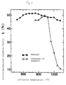
- Fig. 2 shows changes in the electromechanical coupling factor k with the diffusion temperature.
- a ceramic was produced without addition of SiO 2 and B 2 O 3 during preparation of raw materials, and only MnCO 3 in the thermal diffusion paste was adhered to surfaces of the ceramic, and then heat-treated to produce a piezoelectric ceramic in which the adhered compound was diffused into the crystal grain boundary portion.
- a ceramic having the same main component composition as the sample of Example 1 was produced by the same method as Example 1 except that SiO 2 and B 2 O 3 were not added.
- Example 1 On the other hand, only MnCO 3 was kneaded with varnish to prepare the thermal diffusion paste as in Example 1. The thermal diffusion paste was then adhered to both surfaces of the ceramic by screen printing, and heat-treated for 2 hours at the same temperature as Example 1 to diffuse the manganese compound.
- a piezoelectric ceramic was obtained by the same method as Example 1, and then cut into a square 5 x 5 mm plate. The resistivity ⁇ and electromechanical coupling factor K in spreading vibration were measured.
- Fig. 1 shows changes in the resistivity ⁇ with the diffusion temperature
- Fig. 2 shows changes in the electromechanical coupling factor K with the diffusion temperature.
- Fig. 1 reveals that the piezoelectric ceramic in which the manganese compound and the lead borosilicate glass containing Si and B were thermally diffused causes a decrease in resistivity ⁇ at a low thermal diffusion temperature compared with the comparative example in which only the manganese compound was thermally diffused. Also, the comparative example shows an excessive decrease in the resistivity ⁇ at higher temperatures. Therefore, no polarization electric field can be applied, and thus the electromechanical coupling factor K rapidly decreases, as shown in Fig. 2.
- Fig. 1 also indicates that the resistivity ⁇ of the piezoelectric ceramic of Example 2 subjected to thermal diffusion varies less with changes in the thermal diffusion temperature compared with the Comparative Example. Therefore, when a large amount of ceramic is subjected to thermal diffusion, the ceramic of Example 2 is hardly effected by the temperature distribution in the thermal diffusion furnace and the state of the crystal grains of the ceramic composition.
- Fig. 2 indicates that, even if the thermal diffusion temperature changes, the electromechanical coupling factor K of the piezoelectric ceramic of Example 2 subjected to thermal diffusion has a high value over a wide temperature range compared with the Comparative Example.
- SiO 2 and B 2 O 3 were added during preparation of raw materials so as to be contained in the piezoelectric ceramic and a manganese compound was then adhered to the surfaces of the piezoelectric ceramic and heat-treated to diffuse the adhered compound into the crystal grain boundary portion (for example as in Example 1), changes in the resistivity and electromechanical coupling factor with the diffusion temperature have the same tendency as Example 2.
- Table 1 indicates that both changes in the resonance frequency and antiresonance frequency ( ⁇ Fr and ⁇ Fa) are stable and small within the range of the present invention, and thus the piezoelectric ceramic of the present invention is excellent in heat resistance.
- the piezoelectric ceramic the present invention comprises at least a composite oxide of lead, zirconium and titanium, and predetermined amounts of manganese, silicon and boron oxides, wherein the concentration of the manganese oxide present in the crystal grain boundary layer is higher than that in the crystal grains of the piezoelectric ceramic, thereby obtaining characteristics required for a piezoelectric material, i.e., low resistivity ⁇ and a high electromechanical coupling factor K.
- the manganese compound is thermally diffused into the piezoelectric ceramic, a large amount of compound can be stably diffused without being effected by the grain structure changes in the components of the piezoelectric ceramic or the temperature distribution in the thermal diffusion furnace.
- the additive has no effect on the resistivity, etc.
- the MnO 2 content is preferably about 0.005 to 0.32 wt%. More preferably, the amount is about 0.027 - 0.295 wt%.
- the SiO 2 content is preferably about 0.3 wt% or less (excluding 0 wt%). More preferably, the amount is about 0.03 - 0.279 wt%.
- the optimum temperature range of thermal diffusion for thermally diffusing Mn ions into a ceramic becomes very narrow, thereby deteriorating the yield of industrial mass product at low cost.
- the B 2 O 3 content is thus preferably about 0.2 wt% or less (excluding 0 wt%). More preferably, the amount is about 0.038 - 0.192 wt%.
- the piezoelectric ceramic having a main component composition of (Pb 0.95 Sr 0.03 La 0.02 ) (Zr 0.51 Ti 0.49 )O 3 was used in the above examples, the piezoelectric ceramic is not limited to this, and two-component and three-component PZT ceramics having other compositions, and these materials in which lead is partly replaced by Sr, Ba, Ca, La or the like may be used.
- the thermal diffusion paste containing a manganese compound and lead borosilicate at a ratio by weight of 5 : 5 was used, the ratio by weight of both components is not limited to this, and may be set to any desired value consistent with the amounts of metals described above.
- the source of the Si and B can be varied widely as long as the respective oxides in the desired amounts are formed by the end of the production process.
- the source of the Mn can be varied widely as long as the oxide in the desired amount is present in the crystal grain boundary layer at a higher concentration than that in crystal grains of the piezoelectric ceramic by the end of the production process.
- the present invention is capable of decreasing the resistivity of a PZT piezoelectric ceramic and improving the heat resistance thereof.
- the present invention enables the low-cost mass production of a piezoelectric ceramic having a low mechanical quality coefficient Qm, a large electromechanical coupling factor K and low resistivity, and thus having excellent heat resistance, for example, a piezoelectric ceramic for a filter element which can be applied to surface mounting.
Landscapes
- Chemical & Material Sciences (AREA)
- Engineering & Computer Science (AREA)
- Ceramic Engineering (AREA)
- Composite Materials (AREA)
- Manufacturing & Machinery (AREA)
- Materials Engineering (AREA)
- Structural Engineering (AREA)
- Organic Chemistry (AREA)
- Compositions Of Oxide Ceramics (AREA)
Applications Claiming Priority (3)
| Application Number | Priority Date | Filing Date | Title |
|---|---|---|---|
| JP28982795A JP3204056B2 (ja) | 1995-11-08 | 1995-11-08 | 圧電磁器 |
| JP28982795 | 1995-11-08 | ||
| JP289827/95 | 1995-11-08 |
Publications (2)
| Publication Number | Publication Date |
|---|---|
| EP0773594A1 true EP0773594A1 (de) | 1997-05-14 |
| EP0773594B1 EP0773594B1 (de) | 1999-07-21 |
Family
ID=17748291
Family Applications (1)
| Application Number | Title | Priority Date | Filing Date |
|---|---|---|---|
| EP96117960A Expired - Lifetime EP0773594B1 (de) | 1995-11-08 | 1996-11-08 | Piezoelektrische Keramik |
Country Status (7)
| Country | Link |
|---|---|
| US (1) | US5993683A (de) |
| EP (1) | EP0773594B1 (de) |
| JP (1) | JP3204056B2 (de) |
| KR (1) | KR0185029B1 (de) |
| CN (1) | CN1064942C (de) |
| DE (1) | DE69603341T2 (de) |
| TW (1) | TW430639B (de) |
Cited By (1)
| Publication number | Priority date | Publication date | Assignee | Title |
|---|---|---|---|---|
| US5965057A (en) * | 1995-10-06 | 1999-10-12 | Murata Manufacturing Co., Ltd. | Piezoelectric ceramic and manufacturing method thereof |
Families Citing this family (6)
| Publication number | Priority date | Publication date | Assignee | Title |
|---|---|---|---|---|
| KR100323362B1 (ko) * | 1998-08-14 | 2002-06-20 | 박호군 | 온도 특성이 우수한 압전 액츄에이터용 세라믹조성물 |
| CN1067667C (zh) * | 1998-09-18 | 2001-06-27 | 香港理工大学 | 压电陶瓷-压电性聚合物复合材料及其制造方法 |
| JP3908458B2 (ja) * | 1999-12-28 | 2007-04-25 | Tdk株式会社 | 誘電体磁器組成物の製造方法 |
| KR100481718B1 (ko) * | 2001-12-27 | 2005-04-11 | 주식회사 에스세라 | 압전 세라믹 조성물과 그 압전 세라믹 조성물을 이용한 압전소자 |
| JP2009242167A (ja) * | 2008-03-31 | 2009-10-22 | Tdk Corp | 圧電磁器及びそれを用いた圧電素子 |
| JP7078037B2 (ja) * | 2017-03-28 | 2022-05-31 | Tdk株式会社 | 圧電組成物および圧電素子 |
Citations (5)
| Publication number | Priority date | Publication date | Assignee | Title |
|---|---|---|---|---|
| JPH061656A (ja) | 1992-06-23 | 1994-01-11 | Murata Mfg Co Ltd | 圧電磁器 |
| JPH061655A (ja) | 1992-06-23 | 1994-01-11 | Murata Mfg Co Ltd | 圧電磁器 |
| JPH061657A (ja) | 1992-06-23 | 1994-01-11 | Murata Mfg Co Ltd | 圧電磁器 |
| JPH0733521A (ja) * | 1993-07-19 | 1995-02-03 | Murata Mfg Co Ltd | 圧電磁器 |
| JPH0733522A (ja) * | 1993-07-19 | 1995-02-03 | Murata Mfg Co Ltd | 圧電磁器 |
Family Cites Families (6)
| Publication number | Priority date | Publication date | Assignee | Title |
|---|---|---|---|---|
| JPS601656A (ja) * | 1983-06-17 | 1985-01-07 | Fujitsu Ltd | 磁気記録再生装置 |
| JPS61657A (ja) * | 1984-06-12 | 1986-01-06 | 帝人株式会社 | 乾式不織布用ポリエステルバインダ |
| US4588630A (en) * | 1984-06-13 | 1986-05-13 | Chicopee | Apertured fusible fabrics |
| JPH0817054B2 (ja) * | 1989-02-23 | 1996-02-21 | 株式会社村田製作所 | 誘電体磁器組成物 |
| EP0539151B1 (de) * | 1991-10-24 | 1996-04-03 | Matsushita Electric Industrial Co., Ltd. | Dielektrisches-keramisches Verbundmaterial |
| EP0575966B1 (de) * | 1992-06-23 | 1998-04-22 | Murata Manufacturing Co., Ltd. | Piezoelektrische Keramiken |
-
1995
- 1995-11-08 JP JP28982795A patent/JP3204056B2/ja not_active Expired - Lifetime
-
1996
- 1996-11-07 US US08/746,242 patent/US5993683A/en not_active Expired - Fee Related
- 1996-11-08 EP EP96117960A patent/EP0773594B1/de not_active Expired - Lifetime
- 1996-11-08 CN CN961214023A patent/CN1064942C/zh not_active Expired - Fee Related
- 1996-11-08 DE DE69603341T patent/DE69603341T2/de not_active Expired - Lifetime
- 1996-11-08 KR KR1019960052995A patent/KR0185029B1/ko not_active Expired - Fee Related
- 1996-11-14 TW TW085113936A patent/TW430639B/zh not_active IP Right Cessation
Patent Citations (5)
| Publication number | Priority date | Publication date | Assignee | Title |
|---|---|---|---|---|
| JPH061656A (ja) | 1992-06-23 | 1994-01-11 | Murata Mfg Co Ltd | 圧電磁器 |
| JPH061655A (ja) | 1992-06-23 | 1994-01-11 | Murata Mfg Co Ltd | 圧電磁器 |
| JPH061657A (ja) | 1992-06-23 | 1994-01-11 | Murata Mfg Co Ltd | 圧電磁器 |
| JPH0733521A (ja) * | 1993-07-19 | 1995-02-03 | Murata Mfg Co Ltd | 圧電磁器 |
| JPH0733522A (ja) * | 1993-07-19 | 1995-02-03 | Murata Mfg Co Ltd | 圧電磁器 |
Non-Patent Citations (2)
| Title |
|---|
| PATENT ABSTRACTS OF JAPAN vol. 95, no. 002 * |
| TUNKASIRI T: "PROPERTIES OF PZT CERAMICS PREPARED FROM AQUEOUS SOLUTIONS", SMART MATERIALS AND STRUCTURES, vol. 3, no. 2, 1 June 1994 (1994-06-01), pages 243 - 247, XP000455292 * |
Cited By (2)
| Publication number | Priority date | Publication date | Assignee | Title |
|---|---|---|---|---|
| US5965057A (en) * | 1995-10-06 | 1999-10-12 | Murata Manufacturing Co., Ltd. | Piezoelectric ceramic and manufacturing method thereof |
| EP0767152B1 (de) * | 1995-10-06 | 2001-07-18 | Murata Manufacturing Co., Ltd. | Piezoelektrische Keramik und Verfahren zu ihrer Herstellung |
Also Published As
| Publication number | Publication date |
|---|---|
| US5993683A (en) | 1999-11-30 |
| KR0185029B1 (ko) | 1999-04-15 |
| JPH09132456A (ja) | 1997-05-20 |
| EP0773594B1 (de) | 1999-07-21 |
| TW430639B (en) | 2001-04-21 |
| CN1161314A (zh) | 1997-10-08 |
| DE69603341D1 (de) | 1999-08-26 |
| CN1064942C (zh) | 2001-04-25 |
| JP3204056B2 (ja) | 2001-09-04 |
| KR970027013A (ko) | 1997-06-24 |
| DE69603341T2 (de) | 1999-11-11 |
Similar Documents
| Publication | Publication Date | Title |
|---|---|---|
| US6402981B1 (en) | Composition of piezoelectric porcelain | |
| EP0722918B1 (de) | Piezoelektrische keramische Zusammensetzung | |
| KR100200180B1 (ko) | 압전세라믹 및 그의 제조방법 | |
| EP0773594A1 (de) | Piezoelektrische Keramik | |
| EP0767152B1 (de) | Piezoelektrische Keramik und Verfahren zu ihrer Herstellung | |
| US20020049130A1 (en) | Piezoelectric ceramic composition and piezoelectric ceramic element using the same | |
| EP0575966B1 (de) | Piezoelektrische Keramiken | |
| US20020014196A1 (en) | Piezoelectric ceramic material | |
| JP3221147B2 (ja) | 圧電磁器 | |
| US6383411B1 (en) | Piezoelectric ceramic composition and piezoelectric ceramic device using the same | |
| JP3384043B2 (ja) | 圧電磁器 | |
| JP3384044B2 (ja) | 圧電磁器 | |
| JP2001206767A (ja) | 圧電磁器およびその製造方法 | |
| JP3221145B2 (ja) | 圧電磁器 | |
| JP3232667B2 (ja) | 圧電磁器 | |
| JPH061656A (ja) | 圧電磁器 | |
| JPH06252468A (ja) | 圧電磁器 | |
| JPH08231270A (ja) | 圧電磁器組成物 | |
| JPH06263534A (ja) | 圧電磁器 | |
| JPH061655A (ja) | 圧電磁器 | |
| KR20010029246A (ko) | 압전세라믹 조성물 | |
| JPH0558726A (ja) | 圧電磁器および表面実装型圧電部品 | |
| JPH09295864A (ja) | 圧電磁器組成物 | |
| JPS5943105B2 (ja) | 圧電性磁器の製造方法 | |
| JPH0376280A (ja) | 圧電磁器組成物およびその製造方法 |
Legal Events
| Date | Code | Title | Description |
|---|---|---|---|
| PUAI | Public reference made under article 153(3) epc to a published international application that has entered the european phase |
Free format text: ORIGINAL CODE: 0009012 |
|
| 17P | Request for examination filed |
Effective date: 19970313 |
|
| AK | Designated contracting states |
Kind code of ref document: A1 Designated state(s): DE FR NL |
|
| GRAG | Despatch of communication of intention to grant |
Free format text: ORIGINAL CODE: EPIDOS AGRA |
|
| 17Q | First examination report despatched |
Effective date: 19980928 |
|
| GRAG | Despatch of communication of intention to grant |
Free format text: ORIGINAL CODE: EPIDOS AGRA |
|
| GRAH | Despatch of communication of intention to grant a patent |
Free format text: ORIGINAL CODE: EPIDOS IGRA |
|
| GRAH | Despatch of communication of intention to grant a patent |
Free format text: ORIGINAL CODE: EPIDOS IGRA |
|
| GRAA | (expected) grant |
Free format text: ORIGINAL CODE: 0009210 |
|
| AK | Designated contracting states |
Kind code of ref document: B1 Designated state(s): DE FR NL |
|
| REF | Corresponds to: |
Ref document number: 69603341 Country of ref document: DE Date of ref document: 19990826 |
|
| ET | Fr: translation filed | ||
| PLBE | No opposition filed within time limit |
Free format text: ORIGINAL CODE: 0009261 |
|
| STAA | Information on the status of an ep patent application or granted ep patent |
Free format text: STATUS: NO OPPOSITION FILED WITHIN TIME LIMIT |
|
| 26N | No opposition filed | ||
| PGFP | Annual fee paid to national office [announced via postgrant information from national office to epo] |
Ref country code: DE Payment date: 20091105 Year of fee payment: 14 |
|
| PGFP | Annual fee paid to national office [announced via postgrant information from national office to epo] |
Ref country code: NL Payment date: 20091104 Year of fee payment: 14 |
|
| PGFP | Annual fee paid to national office [announced via postgrant information from national office to epo] |
Ref country code: FR Payment date: 20091123 Year of fee payment: 14 |
|
| REG | Reference to a national code |
Ref country code: NL Ref legal event code: V1 Effective date: 20110601 |
|
| REG | Reference to a national code |
Ref country code: FR Ref legal event code: ST Effective date: 20110801 |
|
| REG | Reference to a national code |
Ref country code: DE Ref legal event code: R119 Ref document number: 69603341 Country of ref document: DE Effective date: 20110601 Ref country code: DE Ref legal event code: R119 Ref document number: 69603341 Country of ref document: DE Effective date: 20110531 |
|
| PG25 | Lapsed in a contracting state [announced via postgrant information from national office to epo] |
Ref country code: NL Free format text: LAPSE BECAUSE OF NON-PAYMENT OF DUE FEES Effective date: 20110601 |
|
| PG25 | Lapsed in a contracting state [announced via postgrant information from national office to epo] |
Ref country code: DE Free format text: LAPSE BECAUSE OF NON-PAYMENT OF DUE FEES Effective date: 20110531 |
|
| PG25 | Lapsed in a contracting state [announced via postgrant information from national office to epo] |
Ref country code: FR Free format text: LAPSE BECAUSE OF NON-PAYMENT OF DUE FEES Effective date: 20101130 |