EP0783049A1 - Machine a coudre surjeteuse - Google Patents
Machine a coudre surjeteuse Download PDFInfo
- Publication number
- EP0783049A1 EP0783049A1 EP95913366A EP95913366A EP0783049A1 EP 0783049 A1 EP0783049 A1 EP 0783049A1 EP 95913366 A EP95913366 A EP 95913366A EP 95913366 A EP95913366 A EP 95913366A EP 0783049 A1 EP0783049 A1 EP 0783049A1
- Authority
- EP
- European Patent Office
- Prior art keywords
- thread
- tension
- sewing machine
- feed rate
- overlock sewing
- Prior art date
- Legal status (The legal status is an assumption and is not a legal conclusion. Google has not performed a legal analysis and makes no representation as to the accuracy of the status listed.)
- Granted
Links
- 238000009958 sewing Methods 0.000 title claims abstract description 43
- 230000002093 peripheral effect Effects 0.000 abstract description 6
- 238000000034 method Methods 0.000 description 4
- 230000008878 coupling Effects 0.000 description 2
- 238000010168 coupling process Methods 0.000 description 2
- 238000005859 coupling reaction Methods 0.000 description 2
- 239000004744 fabric Substances 0.000 description 2
- 238000005728 strengthening Methods 0.000 description 1
Images


Classifications
-
- D—TEXTILES; PAPER
- D05—SEWING; EMBROIDERING; TUFTING
- D05B—SEWING
- D05B47/00—Needle-thread tensioning devices; Applications of tensometers
- D05B47/02—Manually-controlled tensioning devices
Definitions
- the present invention relates to an overlock sewing machine, and more particularly, it relates to an overlock sewing machine which can readily switch an ordinary over-edge chain stitch and a rolled seam.
- a rolled seam is formed by employing an overlock sewing machine with one needle and three threads or an overlock sewing machine with one needle and two threads comprising a hook looper, replacing a presser foot and a needle plate with those for the rolled seam, and increasing the tension of a lower looper thread or a looper thread (hereinafter referred to as a bobbin thread) while reducing the feed rate.
- Fig. 1 shows an ordinary over-edge chain stitch which is formed by a conventional overlock sewing machine with one needle and three threads
- Fig. 1 shows an ordinary over-edge chain stitch which is formed by a conventional overlock sewing machine with one needle and three threads
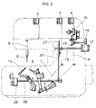
- FIG. 2 shows a conventional rolled seam which is formed by increasing bobbin thread tension (to about twice that in an ordinary over-edge chain stitch) and reducing the feed rate for retracting an upper looper thread to the back side of cloth while reducing the seam pitch.
- the over-edge chain stitch part and the rolled seam part are formed by needle threads 101, upper looper threads 102 and lower looper threads 103.
- Such a rolled seam is generally employed for an over-edge chain stitch for a handkerchief or the like since the cloth edge is rolled and beautified on the upper part.
- An object of the present invention is to provide an overlock sewing machine which can readily perform switching from an over-edge chain stitch to a rolled seam or reverse switching without carrying out a complicated tension adjustment operation.
- the overlock sewing machine comprises a main thread tensioner for providing a bobbin thread with thread tension which is necessary for forming an ordinary over-edge chain stitch, and an auxiliary thread tensioner for providing the bobbin thread with thread tension which is necessary for forming a rolled seam along with the main thread tensioner.
- tension adjustment ranges can be narrowed in both of the main thread tensioner and the auxiliary thread tensioner as compared with that carrying out tension adjustment in a wide range from the over-edge chain stitch to the rolled seam with one thread tensioner by one thread tensioner, whereby the degree of freedom in design of the thread tensioners is advantageously increased.
- the bobbin thread is guided along the main thread tensioner and the auxiliary thread tensioner for the rolled seam to be provided with thread tension from the two thread tensioners, while the bobbin thread is guided along only the main thread tensioner for the over-edge chain stitch along a thread path which is different from that for the rolled seam not to be passed through the auxiliary thread tensioner, or passed through the auxiliary thread tensioner along the same path as that for the rolled seam and tension provision of the auxiliary tensioner is canceled.
- switching of the auxiliary thread tensioner between action and inaction i.e., switching between provision of tension and cancellation thereof is carried out by operation of a manual operation member such as a dial, a lever, a push button or a foot pedal which is provided on an outer side of the sewing machine.
- the thread path may be changed or the auxiliary thread tensioner may be switched between action and inaction in switching between the over-edge chain stitch and the rolled seam, and it is not necessary to carry out tension adjustment in switching of the stitch as to both thread tensioners.
- a switching mechanism for the auxiliary thread tensioner and a feed rate adjusting mechanism are preferably interlocked with each other so that the feed rate is increased when the auxiliary thread tensioner is brought into an inaction state to carry out an over-edge chain stitch while the feed rate is reduced when a rolled seam is formed through action of the auxiliary thread tensioner.
- an end cam for switching the auxiliary thread tensioner may be provided on a shaft of a dial for feed rate adjustment to drive the aforementioned tension releasing pin or pawl or to push the spring or cancel the pushing by the cam.
- the feed rate can be adjusted in the over-edge chain stitch and the rolled seam respectively.
- the aforementioned end cam for switching which is provided on the shaft of the dial may be formed by a double-lift cam having high and low two types of lifts so that the shaft of the dial can be rotated by constant amounts respectively while not changing the state of tension provision or cancellation and the feed rate adjustment is carried out in the respective rotation ranges.
- a switching mechanism for switching the auxiliary thread tensioner to action or inaction is provided.
- the thread path may not be changed in switching between an over-edge chain stitch and a rolled seam.
- switching of the auxiliary thread tensioner to action or inaction and adjustment of the feed rate can be carried out by operation of one manual operation member.
- adjustment of the feed rate can be carried out in switching between the over-edge chain stitch and the rolled seam respectively in an overlock sewing machine interlocking the switching mechanism for the auxiliary thread tensioner and the feed rate adjusting mechanism with each other.
- the feed rate can be adjusted also in the rolled seam in addition to the over-edge chain stitch.
- the cam for switching the auxiliary thread tensioner to action or inaction is formed as a double-lift end cam having high and low two types of lifts, and mounted on the shaft of the dial of the feed rate adjusting mechanism.
- the end cam can be rotationally operated through the feed rate adjusting mechanism.
- the main thread tensioner and the auxiliary thread tensioner are so arranged that the thread paths of the respective thread tensioners are positioned in the same plane so that threads can be readily passed through the thread tensioners.
- thread passage can be carried out by unidirectionally operating the threads on the aforementioned same plane.
- Fig. 1 is a perspective view showing a conventional ordinary over-edge chain stitch with one needle and three threads.
- Fig. 2 is a perspective view showing a conventional rolled seam with one needle and three threads.
- Fig. 3 is a front elevational view showing an overlock sewing machine with one needle and three threads according to an embodiment of the present invention.
- Fig. 4 is a side elevational view of the overlock sewing machine shown in Fig. 3.
- Fig. 5 is a partially fragmented plan view of an auxiliary thread tensioner in an over-edge chain stitch in the overlock sewing machine shown in Fig. 3.
- Fig. 6 is a partially fragmented plan view of the auxiliary thread tensioner upon switching to a rolled seam in the overlock sewing machine shown in Fig. 3.
- Fig. 7 is a side elevational view showing a feed mechanism of the overlock sewing machine shown in Fig. 3.
- Fig. 8 is a perspective view showing another example of the switching mechanism shown in Fig. 3.
- Fig. 9 is a front elevational view of an overlock sewing machine comprising the switching mechanism shown in Fig. 8.
- Fig. 10 is a side elevational view of the overlock sewing machine shown in Fig. 9.
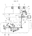
- Fig. 11 is a front elevational view of an overlock sewing machine comprising a switching mechanism of still another example of the switching mechanism shown in Fig. 3.
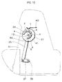
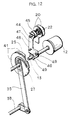
- Fig. 12 is a perspective view of the switching mechanism shown in Fig. 11.
- a thread tensioner 2 for a needle thread a thread tensioner 3 for an upper looper thread and a thread tensioner 4 for a lower looper thread are arranged on a front surface upper part of a sewing machine cover 1.
- a dial 12 for feed rate adjustment is protrudingly provided on a side surface of a sewing machine body 11. The feed rate is adjusted by a rotational operation of this dial 12.
- an auxiliary thread tensioner 15 through which the lower looper thread 9 on the thread path is passed, is provided in the vicinity of the thread tensioner 4. Further, a switching lever 16 for switching action or inaction of the auxiliary thread tensioner 15 is provided adjacently to the dial 12.
- the auxiliary thread tensioner 15 includes a mount 18, a screw shaft 19 which is fastened to the mount 18 to project sideward, a pair of tension discs 20 which are slidably engaged with the screw shaft 19, a spring seat 21 which is screwed to the screw shaft 19, and a coil spring 22 which is freely engaged (movably fitted) with the screw shaft 19 between the spring seat 21 and the tension discs 20 for pressing the tension discs 20, as shown in Figs. 5 and 6.
- An upper pawl 23 and a lower pawl 24 are further integrally attached to the mount 18.
- the upper pawl 23 is directed to the peripheral edges of the tension discs 20, while the lower pawl 24 is engaged with an end cam 25 for switching which is fixed coaxially with the switching lever 16.
- the lower pawl 24 is engaged with a high lift part of the end cam 25, whereby the upper pawl 23 rams the tension disc peripheral edges to incline the tension discs 20 and to expand a portion between the tension discs on the front surface side of the sewing machine cover, so that no presser bar pressure is applied to the lower looper thread 9 which is passed between the tension discs (see Fig. 5).
- the lower pawl 24 is engaged with a lower lift part of the end cam 25 to separate the upper pawl 23 from the tension discs 20, thereby applying tension to the lower looper thread 9 which is passed between the tension discs (see Fig. 6).
- the auxiliary thread tensioner is switched by the rotational operation of the switching lever 16 to inact in the over-edge chain stitch and to act in the rolled seam.
- the lower looper thread 9 is provided with tension by the thread tensioner 4 which is set at tension suitable for the over-edge chain stitch in inaction, while the tension provided by the thread tensioner 4 and tension provided by the auxiliary thread tensioner 15 are applied to the lower looper thread 9 in action so that tension which is suitable for the rolled seam is provided.
- the auxiliary thread tensioner is made to act for increasing the tension which is applied to the lower looper thread 9 as described above, while a presser foot and a needle plate are replaced with parts for the rolled seam, and the feed rate is adjusted to small in general.
- adjustment of the feed rate is carried out by rotationally operating the dial 12 for changing the inclination of a tension box 26 by a feed rate adjusting cam 27 which is fixed to a dial shaft 13.
- a slider 28 which is engaged with the tension box 26 is provided on one end with reference to Fig. 7, so that the slider 28 reciprocates along the tension box 26 by rotational driving of an eccentric shaft 29.
- the amount of reciprocation of a horizontal feed arm 31 reciprocating in the horizontal direction of the figure is changed by inclination of the tension box 26, whereby the amount of reciprocation of a feed dog 32, i.e., the feed rate is changed.
- the switching between action and inaction of the auxiliary thread tensioner 15 by the switching lever 16 and the adjustment of the feed rate by the rotational operation of the dial 12 are separately carried out independently of each other. Therefore, operations of the switching lever 16 and the dial 12 are necessary for switching between the over-edge chain stitch and the rolled seam.
- Figs. 8 to 10 show an example which is thus structured, and the aforementioned end cam 25 is mounted on a dial shaft 13 of a dial 12.
- a pin 36 which is protrudingly provided on a coupling plate 35 is engaged with a cam groove 34 which is formed in a feed rate adjusting cam 27.
- a tension shaft 38 is rotated through the coupling plate 35 and a lever 37 by rotation of the feed rate adjusting cam 27, whereby inclination of a tension box 27 is changed.
- a lower pawl 24 is engaged with a high lift part of the end cam 25 so that an over-edge chain stitch is carried out until the pin 37 is in the range of cam groove parts a to e , and the feed rate is increased from the point a where the feed rate is zero toward a point b , a point c and a point d , so that the feed rate is maximized at the point e .
- the lower pawl 24 is engaged with a lower lift part of the end cam 25 so that a rolled seam is formed, and the feed rate is increased from A toward B.
- a locating spring 40 shown in Fig. 10 is engaged with/stopped at a notch groove 41 which is formed in the peripheral surface of the feed rate adjusting cam 27, for adjustment to typical feed rates in the over-edge chain stitch and in the rolled seam.
- an end cam 25 is formed on a peripheral edge of a feed rate adjusting cam 27, and a spring cap 45 of a coil spring 24 is slidably engaged in a shaft 44 of an auxiliary thread tensioner 15.
- a presser plate 47 pressing the spring cap 45 is rotatably pivotally supported on a support block 46 which is freely engaged with a dial shaft 13 with axial movement being restricted by a retaining ring 49.
- a pin 48 which is engaged with the end cam 25 is protrudingly provided on one side end of the presser plate 47.
- the overlock sewing machine according to the present invention is capable of readily forming a rolled seam with no requirement for a complicated tension adjusting operation. Therefore, it is widely applicable to an overlock sewing machine forming a rolled seam in addition to an over-edge chain stitch.
Landscapes
- Engineering & Computer Science (AREA)
- Textile Engineering (AREA)
- Sewing Machines And Sewing (AREA)
Applications Claiming Priority (1)
| Application Number | Priority Date | Filing Date | Title |
|---|---|---|---|
| PCT/JP1995/000588 WO1996030579A1 (fr) | 1995-03-29 | 1995-03-29 | Machine a coudre surjeteuse |
Publications (3)
| Publication Number | Publication Date |
|---|---|
| EP0783049A1 true EP0783049A1 (fr) | 1997-07-09 |
| EP0783049A4 EP0783049A4 (fr) | 1998-08-12 |
| EP0783049B1 EP0783049B1 (fr) | 2002-10-16 |
Family
ID=14125808
Family Applications (1)
| Application Number | Title | Priority Date | Filing Date |
|---|---|---|---|
| EP95913366A Expired - Lifetime EP0783049B1 (fr) | 1995-03-29 | 1995-03-29 | Machine a coudre surjeteuse |
Country Status (5)
| Country | Link |
|---|---|
| US (1) | US5806448A (fr) |
| EP (1) | EP0783049B1 (fr) |
| AU (1) | AU702855B2 (fr) |
| DE (1) | DE69528595T2 (fr) |
| WO (1) | WO1996030579A1 (fr) |
Cited By (1)
| Publication number | Priority date | Publication date | Assignee | Title |
|---|---|---|---|---|
| US10094056B2 (en) | 2014-09-26 | 2018-10-09 | Abm International, Inc. | Automatic thread tensioning |
Families Citing this family (7)
| Publication number | Priority date | Publication date | Assignee | Title |
|---|---|---|---|---|
| US6202772B1 (en) * | 1998-06-24 | 2001-03-20 | Smith International | Cutting element with canted design for improved braze contact area |
| AT410681B (de) * | 1999-01-21 | 2003-06-25 | Sahl Johannes | Kettenstich-nähmaschine |
| SE526806C2 (sv) | 2004-03-15 | 2005-11-08 | Vsm Group Ab | Trådtillförsel vid symaskin |
| JP4822247B2 (ja) * | 2005-04-01 | 2011-11-24 | Juki株式会社 | ミシンのかがり幅調整装置 |
| CH697309B1 (de) * | 2005-05-09 | 2008-08-15 | Gegauf Fritz Ag | Vorrichtung zum Betätigen mehrerer Funktionen einer Nähmaschine. |
| CN101021034B (zh) * | 2007-03-20 | 2011-09-14 | 新杰克缝纫机股份有限公司 | 一种三针锁式线迹平缝机 |
| US8448588B1 (en) | 2011-08-18 | 2013-05-28 | Leonard Samuel Lindley | Force sensing device adapted for sensing thread tension in a long-arm or mid-arm sewing machine |
Family Cites Families (12)
| Publication number | Priority date | Publication date | Assignee | Title |
|---|---|---|---|---|
| US2157373A (en) * | 1936-12-29 | 1939-05-09 | Willcox & Gibbs Sewing Machine | Thread handling device for sewing machines |
| JPS5934780A (ja) * | 1982-08-21 | 1984-02-25 | Mitsubishi Electric Corp | 画像情報受信装置 |
| JPS5934780U (ja) * | 1982-08-30 | 1984-03-03 | ジューキ株式会社 | ミシンの糸張力調節装置 |
| JPS5946992A (ja) * | 1982-09-08 | 1984-03-16 | ヤマトミシン製造株式会社 | オ−バ−ロツクミシンの地縫と裾引縫との相互転換方法並びに其の装置 |
| JPH06101360B2 (ja) * | 1985-09-09 | 1994-12-12 | 宇宙開発事業団 | スリツプリング用ブラシとその製造方法 |
| JPH0333339Y2 (fr) * | 1985-09-30 | 1991-07-15 | ||
| JPS6294196A (ja) * | 1985-10-18 | 1987-04-30 | ジューキ株式会社 | オ−バ−ロツクミシンの糸張力制御装置 |
| JPH074459B2 (ja) * | 1986-02-21 | 1995-01-25 | 株式会社ジユ−キ | ロツクミシンの糸調子装置 |
| US4825785A (en) * | 1987-05-18 | 1989-05-02 | Union Special Corporation | Latch tacker |
| US4803936A (en) * | 1987-11-04 | 1989-02-14 | Maruzen Sewing Machine Co., Ltd. | Thread tension device for overedge sewing machines |
| JP2864245B2 (ja) * | 1988-12-02 | 1999-03-03 | 蛇の目ミシン工業株式会社 | 縁かがりミシンのほつれ防止縫い装置 |
| JP2885530B2 (ja) * | 1991-04-12 | 1999-04-26 | 株式会社鈴木製作所 | オーバーロックミシンのかがり方式変換装置 |
-
1995
- 1995-03-29 EP EP95913366A patent/EP0783049B1/fr not_active Expired - Lifetime
- 1995-03-29 WO PCT/JP1995/000588 patent/WO1996030579A1/fr not_active Ceased
- 1995-03-29 AU AU20838/95A patent/AU702855B2/en not_active Ceased
- 1995-03-29 US US08/750,193 patent/US5806448A/en not_active Expired - Lifetime
- 1995-03-29 DE DE69528595T patent/DE69528595T2/de not_active Expired - Lifetime
Cited By (1)
| Publication number | Priority date | Publication date | Assignee | Title |
|---|---|---|---|---|
| US10094056B2 (en) | 2014-09-26 | 2018-10-09 | Abm International, Inc. | Automatic thread tensioning |
Also Published As
| Publication number | Publication date |
|---|---|
| AU2083895A (en) | 1996-10-16 |
| DE69528595D1 (de) | 2002-11-21 |
| EP0783049A4 (fr) | 1998-08-12 |
| AU702855B2 (en) | 1999-03-04 |
| EP0783049B1 (fr) | 2002-10-16 |
| US5806448A (en) | 1998-09-15 |
| WO1996030579A1 (fr) | 1996-10-03 |
| DE69528595T2 (de) | 2003-06-18 |
Similar Documents
| Publication | Publication Date | Title |
|---|---|---|
| US5806448A (en) | Overlock sewing machine | |
| JP2686188B2 (ja) | 糸調子器の調節つまみ定位置戻し装置 | |
| JP2008245731A (ja) | ミシン | |
| US6145457A (en) | Sewing machine having needle bar oscillating mechanism, needle bar interrupting mechanism and thread tension releasing mechanism | |
| US4756263A (en) | Fabric feed device of a sewing machine | |
| US5711238A (en) | Overlock sewing machine | |
| JP4822247B2 (ja) | ミシンのかがり幅調整装置 | |
| JPH02211197A (ja) | ミシンの上糸つかみ装置 | |
| US6050205A (en) | Sewing machine with thread tension releasing mechanism | |
| US5875724A (en) | Forward and reverse fabric feed control device with feed control cams for buttonhole sewing machine | |
| US5313900A (en) | Feed direction and stitch length cam for zigzag sewing machine | |
| US4953484A (en) | Overedge sewing machine for cutting the edge of a fabric while sewing an overedge stitch | |
| JPH02154788A (ja) | ロック縫一巻縫自動変換装置 | |
| JPH03286797A (ja) | 刺繍ミシン | |
| US5450804A (en) | Lock stitch machine | |
| JP2917477B2 (ja) | 糸通し装置付きミシン | |
| JPH0796093A (ja) | オーバーロックミシン | |
| JPH05123473A (ja) | 刺しゆう機能付きミシンの押え高さ調整装置 | |
| JPH04135594A (ja) | 糸通過制御可能なミシン | |
| JP2993295B2 (ja) | 刺繍ミシンのジャンプ縫い機構 | |
| JP3818686B2 (ja) | ミシンの糸調子迅速切替え装置 | |
| JPH0938367A (ja) | ミシン | |
| JP2636774B2 (ja) | まとめ縫いミシンのほつれ止め装置 | |
| JP2679512B2 (ja) | ミシンの上送り歯駆動機構 | |
| JP2004141440A (ja) | 飾り縫いミシン |
Legal Events
| Date | Code | Title | Description |
|---|---|---|---|
| PUAI | Public reference made under article 153(3) epc to a published international application that has entered the european phase |
Free format text: ORIGINAL CODE: 0009012 |
|
| 17P | Request for examination filed |
Effective date: 19961220 |
|
| AK | Designated contracting states |
Kind code of ref document: A1 Designated state(s): DE IT |
|
| A4 | Supplementary search report drawn up and despatched | ||
| AK | Designated contracting states |
Kind code of ref document: A4 Designated state(s): DE IT |
|
| 17Q | First examination report despatched |
Effective date: 20000929 |
|
| GRAG | Despatch of communication of intention to grant |
Free format text: ORIGINAL CODE: EPIDOS AGRA |
|
| GRAG | Despatch of communication of intention to grant |
Free format text: ORIGINAL CODE: EPIDOS AGRA |
|
| GRAH | Despatch of communication of intention to grant a patent |
Free format text: ORIGINAL CODE: EPIDOS IGRA |
|
| GRAH | Despatch of communication of intention to grant a patent |
Free format text: ORIGINAL CODE: EPIDOS IGRA |
|
| GRAA | (expected) grant |
Free format text: ORIGINAL CODE: 0009210 |
|
| AK | Designated contracting states |
Kind code of ref document: B1 Designated state(s): DE IT |
|
| REF | Corresponds to: |
Ref document number: 69528595 Country of ref document: DE Date of ref document: 20021121 |
|
| PLBE | No opposition filed within time limit |
Free format text: ORIGINAL CODE: 0009261 |
|
| STAA | Information on the status of an ep patent application or granted ep patent |
Free format text: STATUS: NO OPPOSITION FILED WITHIN TIME LIMIT |
|
| 26N | No opposition filed |
Effective date: 20030717 |
|
| PGFP | Annual fee paid to national office [announced via postgrant information from national office to epo] |
Ref country code: IT Payment date: 20120321 Year of fee payment: 18 |
|
| PGFP | Annual fee paid to national office [announced via postgrant information from national office to epo] |
Ref country code: DE Payment date: 20130327 Year of fee payment: 19 |
|
| REG | Reference to a national code |
Ref country code: DE Ref legal event code: R119 Ref document number: 69528595 Country of ref document: DE |
|
| REG | Reference to a national code |
Ref country code: DE Ref legal event code: R119 Ref document number: 69528595 Country of ref document: DE Effective date: 20141001 |
|
| PG25 | Lapsed in a contracting state [announced via postgrant information from national office to epo] |
Ref country code: DE Free format text: LAPSE BECAUSE OF NON-PAYMENT OF DUE FEES Effective date: 20141001 |
|
| PG25 | Lapsed in a contracting state [announced via postgrant information from national office to epo] |
Ref country code: IT Free format text: LAPSE BECAUSE OF NON-PAYMENT OF DUE FEES Effective date: 20140329 |