EP0784246A2 - Gerät zur Bilderzeugung unter Verwendung eines Zwischenübertragungselementes - Google Patents
Gerät zur Bilderzeugung unter Verwendung eines Zwischenübertragungselementes Download PDFInfo
- Publication number
- EP0784246A2 EP0784246A2 EP97300098A EP97300098A EP0784246A2 EP 0784246 A2 EP0784246 A2 EP 0784246A2 EP 97300098 A EP97300098 A EP 97300098A EP 97300098 A EP97300098 A EP 97300098A EP 0784246 A2 EP0784246 A2 EP 0784246A2
- Authority
- EP
- European Patent Office
- Prior art keywords
- toner
- transfer
- intermediary transfer
- image
- bias
- Prior art date
- Legal status (The legal status is an assumption and is not a legal conclusion. Google has not performed a legal analysis and makes no representation as to the accuracy of the status listed.)
- Granted
Links
- 238000012546 transfer Methods 0.000 title claims abstract description 325
- 238000004140 cleaning Methods 0.000 claims abstract description 62
- 239000000463 material Substances 0.000 claims abstract description 53
- 238000000034 method Methods 0.000 claims description 16
- 239000003086 colorant Substances 0.000 claims description 10
- 238000011161 development Methods 0.000 claims description 2
- 239000002699 waste material Substances 0.000 description 14
- 230000008569 process Effects 0.000 description 9
- 230000007246 mechanism Effects 0.000 description 6
- 230000005684 electric field Effects 0.000 description 5
- 238000003854 Surface Print Methods 0.000 description 3
- 238000012423 maintenance Methods 0.000 description 3
- XAGFODPZIPBFFR-UHFFFAOYSA-N aluminium Chemical compound [Al] XAGFODPZIPBFFR-UHFFFAOYSA-N 0.000 description 1
- 229910052782 aluminium Inorganic materials 0.000 description 1
- 238000013459 approach Methods 0.000 description 1
- 230000015572 biosynthetic process Effects 0.000 description 1
- 210000000078 claw Anatomy 0.000 description 1
- 230000000593 degrading effect Effects 0.000 description 1
- 239000003989 dielectric material Substances 0.000 description 1
- 230000004069 differentiation Effects 0.000 description 1
- 238000004519 manufacturing process Methods 0.000 description 1
- 238000012986 modification Methods 0.000 description 1
- 230000004048 modification Effects 0.000 description 1
- 230000003287 optical effect Effects 0.000 description 1
- 230000004044 response Effects 0.000 description 1
- 238000000926 separation method Methods 0.000 description 1
- 229910001220 stainless steel Inorganic materials 0.000 description 1
- 239000010935 stainless steel Substances 0.000 description 1
Images



Classifications
-
- G—PHYSICS
- G03—PHOTOGRAPHY; CINEMATOGRAPHY; ANALOGOUS TECHNIQUES USING WAVES OTHER THAN OPTICAL WAVES; ELECTROGRAPHY; HOLOGRAPHY
- G03G—ELECTROGRAPHY; ELECTROPHOTOGRAPHY; MAGNETOGRAPHY
- G03G15/00—Apparatus for electrographic processes using a charge pattern
- G03G15/14—Apparatus for electrographic processes using a charge pattern for transferring a pattern to a second base
- G03G15/16—Apparatus for electrographic processes using a charge pattern for transferring a pattern to a second base of a toner pattern, e.g. a powder pattern, e.g. magnetic transfer
- G03G15/1605—Apparatus for electrographic processes using a charge pattern for transferring a pattern to a second base of a toner pattern, e.g. a powder pattern, e.g. magnetic transfer using at least one intermediate support
- G03G15/161—Apparatus for electrographic processes using a charge pattern for transferring a pattern to a second base of a toner pattern, e.g. a powder pattern, e.g. magnetic transfer using at least one intermediate support with means for handling the intermediate support, e.g. heating, cleaning, coating with a transfer agent
-
- G—PHYSICS
- G03—PHOTOGRAPHY; CINEMATOGRAPHY; ANALOGOUS TECHNIQUES USING WAVES OTHER THAN OPTICAL WAVES; ELECTROGRAPHY; HOLOGRAPHY
- G03G—ELECTROGRAPHY; ELECTROPHOTOGRAPHY; MAGNETOGRAPHY
- G03G2215/00—Apparatus for electrophotographic processes
- G03G2215/16—Transferring device, details
- G03G2215/1647—Cleaning of transfer member
- G03G2215/1652—Cleaning of transfer member of transfer roll
-
- G—PHYSICS
- G03—PHOTOGRAPHY; CINEMATOGRAPHY; ANALOGOUS TECHNIQUES USING WAVES OTHER THAN OPTICAL WAVES; ELECTROGRAPHY; HOLOGRAPHY
- G03G—ELECTROGRAPHY; ELECTROPHOTOGRAPHY; MAGNETOGRAPHY
- G03G2215/00—Apparatus for electrophotographic processes
- G03G2215/16—Transferring device, details
- G03G2215/1647—Cleaning of transfer member
- G03G2215/1657—Cleaning of transfer member of transfer drum
-
- G—PHYSICS
- G03—PHOTOGRAPHY; CINEMATOGRAPHY; ANALOGOUS TECHNIQUES USING WAVES OTHER THAN OPTICAL WAVES; ELECTROGRAPHY; HOLOGRAPHY
- G03G—ELECTROGRAPHY; ELECTROPHOTOGRAPHY; MAGNETOGRAPHY
- G03G2215/00—Apparatus for electrophotographic processes
- G03G2215/16—Transferring device, details
- G03G2215/1647—Cleaning of transfer member
- G03G2215/1661—Cleaning of transfer member of transfer belt
Definitions
- the present invention relates to a cleaning means installed in an image forming apparatus to clean an intermediary transfer member of the image forming apparatus in which a toner image formed on an image bearing member is transferred onto a transfer material with the use of the intermediary transfer member.
- the transfer material is conveyed by the intermediary transfer member and a transferring means, being pinched by the intermediary transfer member and transferring means in such a manner that the front and back sides of the transfer material make contact with the intermediary transfer member and transferring means, respectively.
- the means for cleaning the intermediary transfer member and transferring means there are a brush cleaner such as the one disclosed in Japanese Laid-Open Patent Application No. 102385/1991, a blade such as the one disclosed in Japanese Laid-Open Patent Application No. 60569/1994, a cleaning roller such as the one disclosed in Japanese Laid-Open Patent Application No. 134560/1993, and the like. Also, there is a method such as the one disclosed in Japanese Laid-Open Patent Application No. 164226/1992, in which cleaning is rendered easier by applying a reverse bias to an intermediary transfer member.
- each of the above described methods in which a brush cleaner, a blade, or cleaning roller is employed, requires a dedicated waste toner container to collect the untransferred toner removed by cleaning.
- the waste toner collected in this waste toner container must be removed therefrom and disposed before the waste toner container is filled up with the collected waste toner. Therefore, if the waste toner container is small, the waste toner disposal operation must be frequently carried out, which is quite annoying.
- the waste toner container is large, the frequency of the waste toner disposal operation is smaller. In other words, the large waste toner container is better in terms of maintenance. But it occupies a large space, being liable to increase the overall size of an image forming apparatus, which is a problem.
- the method in which a bias having the same polarity as the waste toner is applied to an intermediary transfer member itself to transfer the waste toner onto a photosensitive drum, is different from the aforementioned three methods in that it is unnecessary to provide the intermediary transfer member with a container for collecting the waste toner.
- this method also has a problem in that its cleaning performance is low.
- a primary object of the present invention is to provide an image forming apparatus comprising an intermediary transfer member, which further comprises such a cleaning means that is capable of displaying desirable cleaning efficiency, without degrading maintenance efficiency, and also without inviting increase in apparatus size.
- an image forming apparatus which employs an intermediary transfer member to form a toner image on a piece of transfer material, comprises: an image bearing member; a toner image forming means for forming a toner image on the image bearing member; an intermediary endless transfer member placed in contact with the image bearing member; a first bias applying means for generating a first transfer bias between the image bearing member and the intermediary transfer member to transfer the toner image formed on the image bearing member onto the intermediary transfer member at a first transfer point of the intermediary transfer member (primary transfer); a second bias applying means for generating a second transfer bias between the intermediary transfer member and a transferring means to transfer the toner image having been transferred onto the intermediary transfer member onto the transfer material at a second transfer point of the intermediary transfer member; and a third bias applying means for applying voltage to an electrode for charging the residual toner remaining on the intermediary transfer member, to transfer the residual toner remaining on the intermediary transfer member back to the image bearing member after the primary transfer, wherein the first bias applying means for generating a first
- Figure 1 is a schematic drawing depicting the intermediary transfer drum and cleaning means in the first embodiment of the present invention.
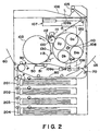
- Figure 2 is a longitudinal sectional view of the image forming apparatus in the first embodiment, depicting the general structure thereof.
- Figure 3 is a timing chart showing the operational timing for each of the switches in the first embodiment.
- Figure 4 is a schematic drawing of the intermediary transfer drum and cleaning means in the second embodiment of the present invention.
- Figure 5 is a timing chart showing the operational timing for each of the switches in the second embodiment.
- FIG. 2 shows the general structure of a full-color (based on four primary colors) laser beam printer (LBP) as a typical image forming apparatus in accordance with the present invention.
- LBP laser beam printer
- electrostatic latent images corresponding to yellow (Y), cyan (C), black (Bk), and magenta (M) colors are sequentially formed on the surface of a photosensitive drum 100 by an optical unit 107 in response to the image information sent per each of the four primary colors. They are sequentially developed into toner images by the color-correspondent developing devices Dy, Dc, Db and Dm (hereinafter, "developing device 120" when differentiation is unnecessary among them), and then are sequentially transferred onto an intermediary transfer drum 103, as the intermediary transfer member, at a first transfer point, effecting thereby a multicolor image.
- developer device 120 when differentiation is unnecessary among them
- the toner images integrally effecting the multicolor image are transferred together onto a transfer material P conveyed to the nip formed by the second transfer point of the intermediary transfer drum 103 and a transfer/conveyance belt (hereinafter, simply "transfer belt 50") as a transfer member.
- the transfer material P having received the multi-color toner image is sent to a fixing unit 104, in which the toner image is fixed to the transfer material P.
- the transfer material P is discharged from a sheet delivery portion 105 into a top sheet delivery tray 106 or a bottom sheet delivery tray 115.
- the developing device 120 it is supported in such a manner that it can be rotated, maintaining a predetermined orientation, by a developing device selection mechanism 108.
- the developing device selection mechanism 108 is rotatively supported by a selection mechanism support frame 109. Further, the selection mechanism support frame 109 is pivoted by a top support point 109b, at the top portion, and is connected to a solenoid 109a, at the bottom portion.
- the developing device 120 selected for developing the next image is moved to a predetermined position by the rotation of the developing device selection mechanism 108, and then, the selection mechanism support frame 109 is moved leftward of the drawing by the solenoid 109a, whereby the developing device 120 is moved to a predetermined developing position (position of developing device Dy in the same drawing).
- the photosensitive drum 100 is uniformly charged (to -700 V, for example) to a predetermined polarity by a charger 111, and then, is exposed to a laser beam L.
- the first latent image for example, the latent image corresponding to the magenta color
- the photosensitive drum is developed in reverse by the magenta image developing device Dm, whereby the first toner image, that is, the magenta toner image, is formed on the photosensitive drum 100.
- a transfer bias voltage (for example, +100 V) having the polarity opposite to that of the toner is applied to the intermediary transfer drum 103 with a predetermined timing, whereby the first toner image on the photosensitive drum 100 is transferred onto the intermediary transfer drum 103 at the first transfer point (primary transfer).
- the photosensitive drum 100 is cleaned of the residual toner remaining after the magenta image transfer, by a known cleaner 112 such as a blade or a brush, to be prepared for the following latent image formation process and latent image development process.
- the second latent image a cyan color image in this embodiment
- the photosensitive drum 100 by the laser beam L, and is developed by the cyan color developing device Dc, whereby the second toner image corresponding to the cyan toner is formed on the photosensitive drum 100.
- the second toner image that is, the image corresponding to the cyan color
- the intermediary transfer drum 103 is transferred onto the intermediary transfer drum 103 in a manner to be superimposed onto the first toner image, that is, the magenta color image, at the first transfer point (primary transfer).
- the third and fourth latent images correspondent to the yellow and black color, respectively, are sequentially formed on the photosensitive drum 100, are sequentially developed into the third and fourth toner images, that is, the yellow and block toner images, by the developing devices Dy and Db, and are sequentially transferred onto the intermediary transfer drum 103, in a manner to be superimposed onto the toner images having been transferred thereon ahead of them (primary transfer). Consequently, four toner images of different primary colors are superimposed on the intermediary transfer drum 103.
- a bias voltage for example, +2.0 kV
- a transfer belt 50 is placed in contact with the intermediary transfer drum 103.
- a transfer material P picked up from a manual sheet feeder tray, or a sheet feeder cassette 201, 202, 203, or 204 is fed into the nip formed by the intermediary transfer drum 103 and the transfer belt 50.
- the four color images of different primary colors, effecting the multicolor toner image are transferred together onto the transfer material P (secondary transfer).
- a bias having a value (for example, -3.0 kV) opposite to the value of the bias applied to the transfer belt 50 is applied to a discharge needle 51 disposed on the trailing end of the transfer belt 50 to discharge the accumulated electric charge (having the polarity opposite to that of the toner charge), until the trailing end of the transfer material P leaves the intermediary transfer drum 103. Meanwhile, as soon as the trailing end of the transfer material P reaches the primary transfer completion point (exit side of the nip formed by the photosensitive drum 100 and the intermediary transfer drum 103), the primary transfer bias voltage being applied to the intermediary transfer drum 103 is turned off (ground potential).
- the transfer material P having been separated from the transfer belt 50 and intermediary transfer drum 103 is conveyed to a fixing device 104, in which the toner image on the transfer material P is fixed to the transfer material P. Thereafter, the transfer material P is discharged into the top sheet delivery tray 115 or bottom sheet delivery tray 106.
- the transfer material P is conveyed toward a two surface printing unit after the toner image is fixed to the transfer material P in the aforementioned printing sequence.
- a switchback roller 70 is rotated in the sheet conveyance direction to hold the transfer material P, and then, immediately before the trailing end of the transfer material P reaches the switchback roller 70, the rotation of the switchback roller 70 is reversed to convey the transfer material P into the two surface printing sheet conveyance path 80 located below the fixing device 104. Thereafter, the aforementioned printing sequence is carried out. Then, the transfer material P printed on both surfaces is discharged onto the bottom sheet delivery tray 115 or top sheet delivery tray 106.
- a reference numeral 113 designates a separation claw for separating the transfer material P when the transfer material P sticks to the intermediary transfer drum 103 in a manner to wrap around it.
- FIG. 1 shows the basic structure therefor.
- switches S3 and S4 constitute the second bias applying means
- switches S5 and S6 constitutes the third bias applying means.
- These switches S3 - S6 join a cleaning member 130 in forming a cleaning means.
- the intermediary transfer drum 103 is composed of an electrically conductive base member, that is, a drum of stainless steel or aluminum, and a layer of dielectric material placed on the surface of the base member.
- the transfer bias is applied to the base member.
- the switches S1 and S2 for applying a positive bias and a negative bias, respectively, to the base member are connected to the base member (first bias applying means).
- the transfer belt 50 is composed of an electrically conductive belt, and the switches S3 and S4 for applying a positive bias and a negative bias, respectively, to the transfer belt 50 are connected to this belt (second bias applying means).
- a cleaning roller (cleaning means) 130 is positioned between the transfer belt 50 and the photosensitive drum 100, after the transfer belt 50 relative to the rotational direction of (counterclockwise direction in Figure 1) of the intermediary transfer drum 103, in a manner to be immediately adjacent to the surface of the intermediary transfer drum 103.
- the switches S5 and S6 for applying a positive bias and a negative bias, respectively, to the cleaning roller 130 is connected (third bias applying means).
- a switch S7 for applying an AC voltage and a negative bias is connected to a charger 111.
- the switch S7 connected to the charger 111 provided for charging the photosensitive drum 100 is turned on to apply a voltage composed by superposing an AC voltage component and a DC voltage component.
- the switch S1 which is connected to the intermediary transfer drum 103 to transfer the toner on the photosensitive drum 100 onto the intermediary transfer drum 103, is turned on to apply a position bias to the intermediary transfer drum 103 (intermediary transfer drum 103 is rotated in the counterclockwise direction).
- the toner image is transferred onto the intermediary transfer drum 103 (primary transfer).
- the transfer material P is conveyed to transfer the toner image onto the transfer material P.
- the cleaning roller 130 it is kept away from the intermediary transfer drum 130 until the above operational sequence ends.
- the switch S3 connected to the transfer belt 50 is turned on to apply a positive bias to the transfer belt 50.
- the transfer belt 50 is placed in contact with the intermediary transfer drum 103.
- the transfer belt 50 is moved away from the intermediary transfer drum 103.
- the cleaning roller 130 is placed in contact with the intermediary transfer drum 103, and the switch S5 connected to the cleaning roller 130 is turned on to apply a positive bias, which is a bias having the polarity opposite to the normal polarity of the toner, to the cleaning roller 130.
- the untransferred toner on the intermediary transfer drum 103 As the positive bias is applied to the cleaning roller 130, the untransferred toner on the intermediary transfer drum 103, which has been positively charged by the positive bias of the transfer belt 50, is re-charged.
- the intermediary transfer drum 130 As the intermediary transfer drum 130 is rotated, the positively re-charged untransferred toner carried on the surface of the intermediary transfer drum 130 is conveyed to a region in which an alternating electric field comprising a DC component is generated between the intermediary transfer drum 103 and the photosensitive drum 100.
- the positively re-charged residual toner is transferred from the surface of the intermediary transfer drum 103 to the surface of the photosensitive drum 100 by the alternating electric field.
- the untransferred toner is removed from the photosensitive drum 100 by the cleaner 112.
- the application of the alternating electric field is not a requisite; it may be applied as needed.
- the above method for removing the residual toner on the intermediary transfer drum 103 is effective also in the case of continuous printing. Since it can transfer the residual toner on the intermediary transfer drum 103 back to the photosensitive drum 100 while transferring the toner image formed on the photosensitive drum 100 onto the intermediary transfer drum 103, without disturbing the toner image, it can prints without reducing the throughput.
- the switches S2, S4, and S6 are kept in the OFF state. A typical timing therefor is shown in detail in Figure 3(a).
- the untransferred toner remaining on the intermediary transfer drum 103 during the aforementioned printing sequence includes not only the toner charged positively by the positive bias of the transfer belt 50, but also the untransferred toner remaining negatively charged after it is negative charged by the transfer device (unillustrated). This negatively charged untransferred toner, which is naturally attracted by the positive bias of the cleaning roller 130, adheres to the cleaning roller 130.
- the adhesion of the negatively charged untransferred toner to the cleaning roller 130 continuously occurs, and as the amount of the negatively charged untransferred toner adhering to the cleaning roller 130 increases, the contact surface between the cleaning roller 130 and the intermediary transfer drum 103 becomes uneven due to the appearance of stepped portions created by the toner adhering to the cleaning roller 130, which is liable to cause the intermediary transfer drum 103 to be insufficiently cleaned. Therefore, a countermeasure must be taken to prevent the occurrence of this problem. As for such a countermeasure, it is effective to clean the cleaning roller 130 at the completion of the printing sequence.
- the switch S7 connected to the charger 111 is turned on after the completion of a normal printing sequence, or during a period before the printing sequence, that is, a period in which an image is not formed. Then, the switch S2 connected to the intermediary transfer drum 103 is turned on to apply a negative bias to the intermediary transfer drum 103. Next, the cleaning roller 130 is placed in contact with the intermediary transfer drum 103, and the switch S6 is turned on to apply a negative bias to the cleaning roller 130. As a result, the negative charged untransferred toner adhering to the cleaning roller 130 transfers onto the intermediary transfer drum 103 due to electrostatic repulsion.
- the untransferred toner having transferred onto the intermediary transfer drum 103 is transferred from the intermediary transfer drum 103 to the photosensitive drum 100 by the electric field generated between the intermediary transfer drum 103 and the photosensitive drum 100 as described above, and is removed by the cleaner 112.
- This process is carried out while the intermediary transfer drum 103 rotates several times to return to its reference position.
- the cleaning roller 130 is kept always clean; the intermediary transfer drum 103 is always cleaned by the clean cleaning roller 130.
- the switches S1, S3, S4 and S5 are in the OFF status, and the transfer belt 50 is kept away from the intermediary transfer drum 103.
- a typical timing therefor is shown in detail in Figure 3(b).
- the transfer material P sometimes fails to reach the transfer belt 50 due to various causes, for example, a jam. Also, a jam sometimes occurs at the transfer point after the transfer material P reaches the transfer belt 50. In such a case, the image formed on the intermediary transfer drum 103 is transferred onto the transfer belt 50. If the next printing operation carried out while the apparatus is in this condition, the back side of the following transfer material P is soiled, and in addition, after the transfer, the transfer material conveyance path is liable to be soiled by the transfer material P which has been soiled on the back side. In order to prevent the occurrence of the above trouble, it is also necessary to clean the transfer belt 50.
- the transfer belt 50 and cleaning roller 130 which have been kept in contact with the intermediary transfer drum 103, are separated from the intermediary transfer drum 103, and then, the switch S3 and S5, which have been kept in the ON condition, are turned off. Thereafter, the switch S1 is turned off, and the switch S2 is turned on to apply a negative bias to the intermediary transfer drum 103, so that while the intermediary transfer drum 103 is rotated several time, the negatively charged untransferred toner on the intermediary transfer drum 103 is electrostatically transferred onto the photosensitive drum 100, and is removed by the cleaner 112.
- the switch S4 connected to the transfer belt 50 is turned on without changing the status of the switch S2, and the transfer belt 50 is placed in contact with the intermediary transfer drum 103, in order to transfer the untransferred toner having been transferred onto the transfer belt 50, back onto the intermediary transfer drum 103. Thereafter, the untransferred toner having been transferred back onto the intermediary transfer drum 103 is transferred back onto the photosensitive drum 100, and is removed by the cleaner 112. This operation is completed while the transfer belt 50 rotates several times.
- a reference symbol RS designates a pulse which serves as a reference for the operational timing of each switch.
- Figure 4 is a schematic drawing of the image forming apparatus in the second embodiment of the present invention, depicting the general structure thereof.
- a reference numeral 200 designates a intermediary transfer belt as the intermediary transfer member, which has the same function as the intermediary transfer drum 103 described in the first embodiment. Since this embodiment is substantially the same in terms of structure as the first embodiment, except for the intermediary transfer belt 200, and the switches S1 and S2 for applying a positive bias and a negative bias, respectively, to the intermediary transfer belt 200, the description thereof will be omitted.
- the cleaning sequence in this second embodiment 2 which is shown in Figures 5(a), 5(b) and 5(c), is the same as the sequence shown in FIgure 3(a), 3(b) and 3(c) depicting the first embodiment, except that in Figures 5(a), 5(b) and 5(c), switches S11 and S12 are employed in place of the switch S1 and S2 illustrated in Figures 3(a), 3(b) and 3(c).
- the switches S11 and S12 function in the same manner as the switch S1 and switch S12, respectively.
- the voltage applied to the charger is a voltage composed by superposing a DC voltage component in a range of -570 V to -600 V, and an AC voltage component having a frequency of 1100 Hz and a Vpp of 2300 V, and is applied under constant current control.
- the voltage applied to the intermediary transfer drum 103 it is a DC voltage of +100 V during a transfer period, and is a DC voltage of -1000 V during a cleaning period.
- the voltage applied to the transfer belt it is a DC voltage in a range of 1000 V to 2000 V during a transfer period, and is a DC voltage of -1000 V during a cleaning period.
- the voltage applied to the electrode roller 130 it is a DC voltage of 2000 V when it is a positive voltage, and is a DC voltage of -1000 V when it is a negative voltage.
- the transfer belt and the electrode roller are under constant current control.
- a bias is applied to a cleaning member to charge the untransferred toner remaining on an intermediary transfer member.
- the charge given to the untransferred toner on the intermediary transfer member makes it easier for the untransferred toner on the intermediary transfer member to be transferred onto an image bearing member. Therefore, the untransferred toner can be effectively removed without the need for the container for collecting the untransferred toner, and hence, without reducing maintenance efficiency or inviting increase in the apparatus size.
- electric power sources having opposing polarity are paired to be used as first, second and third bias applying means, but this arrangement is not requisite. All that is necessary is to generate an electric field capable of transferring toner in the cleaning direction. Therefore, electric power sources which are the same in polarity but different in potential may be employed.
- the configuration of the photosensitive member is not limited to a drum-like configuration; the photosensitive member may be in the form of a belt, for example.
- the electrode for charging the transferring means or the electrode for charging the residual toner may be in the modified form; for example, it may be in the form of a roller or a belt.
- the means for charging the photosensitive member comprises an alternating electric power source; a DC electric power alone can be effectively used.
Landscapes
- Physics & Mathematics (AREA)
- General Physics & Mathematics (AREA)
- Electrostatic Charge, Transfer And Separation In Electrography (AREA)
Applications Claiming Priority (2)
| Application Number | Priority Date | Filing Date | Title |
|---|---|---|---|
| JP2640/96 | 1996-01-10 | ||
| JP264096 | 1996-01-10 |
Publications (3)
| Publication Number | Publication Date |
|---|---|
| EP0784246A2 true EP0784246A2 (de) | 1997-07-16 |
| EP0784246A3 EP0784246A3 (de) | 1999-03-10 |
| EP0784246B1 EP0784246B1 (de) | 2006-04-19 |
Family
ID=11534981
Family Applications (1)
| Application Number | Title | Priority Date | Filing Date |
|---|---|---|---|
| EP97300098A Expired - Lifetime EP0784246B1 (de) | 1996-01-10 | 1997-01-09 | Gerät zur Bilderzeugung unter Verwendung eines Zwischenübertragungselementes |
Country Status (3)
| Country | Link |
|---|---|
| US (1) | US5923939A (de) |
| EP (1) | EP0784246B1 (de) |
| DE (1) | DE69735690T2 (de) |
Cited By (1)
| Publication number | Priority date | Publication date | Assignee | Title |
|---|---|---|---|---|
| DE19837418A1 (de) * | 1997-08-18 | 1999-04-29 | Ricoh Kk | Bilderzeugungsapparat |
Families Citing this family (11)
| Publication number | Priority date | Publication date | Assignee | Title |
|---|---|---|---|---|
| TW510153B (en) * | 2001-05-09 | 2002-11-11 | Hannstar Display Corp | Low cross-section circuit apparatus for liquid crystal display module and manufacturing method of the same |
| JP4386262B2 (ja) * | 2004-02-04 | 2009-12-16 | キヤノン株式会社 | 画像形成装置 |
| JP2005221676A (ja) * | 2004-02-04 | 2005-08-18 | Canon Inc | 画像形成装置およびその制御方法 |
| JP2005221677A (ja) * | 2004-02-04 | 2005-08-18 | Canon Inc | 画像形成装置 |
| JP4418689B2 (ja) * | 2004-02-04 | 2010-02-17 | キヤノン株式会社 | 画像形成装置 |
| JP4371840B2 (ja) * | 2004-02-06 | 2009-11-25 | キヤノン株式会社 | シート処理装置及び画像形成装置 |
| US7228088B2 (en) * | 2005-01-21 | 2007-06-05 | Kabushiki Kaisha Toshiba | Color image forming apparatus and color image forming method |
| JP4372716B2 (ja) * | 2005-04-27 | 2009-11-25 | シャープ株式会社 | 転写装置および画像形成装置 |
| JP4760365B2 (ja) * | 2005-12-26 | 2011-08-31 | ブラザー工業株式会社 | 画像形成装置 |
| JP2008185989A (ja) * | 2007-01-31 | 2008-08-14 | Ricoh Co Ltd | 画像形成装置 |
| JP5590873B2 (ja) * | 2009-12-18 | 2014-09-17 | キヤノン株式会社 | 画像形成装置 |
Citations (4)
| Publication number | Priority date | Publication date | Assignee | Title |
|---|---|---|---|---|
| JPH03102385A (ja) | 1989-09-18 | 1991-04-26 | Minolta Camera Co Ltd | クリーニング装置 |
| JPH04164226A (ja) | 1990-10-29 | 1992-06-09 | Eiken Kizai Kk | 液状検体細胞診検査用固定液 |
| JPH05134560A (ja) | 1991-11-08 | 1993-05-28 | Mita Ind Co Ltd | 転写装置 |
| JPH0660569A (ja) | 1992-08-05 | 1994-03-04 | Hitachi Ltd | 磁気ディスク装置 |
Family Cites Families (24)
| Publication number | Priority date | Publication date | Assignee | Title |
|---|---|---|---|---|
| JPS5463838A (en) * | 1977-10-31 | 1979-05-23 | Ricoh Co Ltd | Method of cleaning trasfer roller of zerographic copying machine |
| JPS56153357A (en) * | 1980-04-29 | 1981-11-27 | Konishiroku Photo Ind Co Ltd | Copying device |
| US4461563A (en) * | 1982-10-22 | 1984-07-24 | Xerox Corporation | Copy sheet contamination prevention |
| JPH01105980A (ja) * | 1987-10-19 | 1989-04-24 | Sharp Corp | 残留物転写機構を有する画像形成装置 |
| CN1038277C (zh) * | 1987-12-28 | 1998-05-06 | 佳能公司 | 成象设备 |
| US5198863A (en) * | 1988-06-29 | 1993-03-30 | Canon Kabushiki Kaisha | Image forming apparatus |
| US5179397A (en) * | 1989-04-03 | 1993-01-12 | Canon Kabushiki Kaisha | Image forming apparatus with constant voltage and constant current control |
| US5264902A (en) * | 1990-02-07 | 1993-11-23 | Canon Kabushiki Kaisha | Image forming device |
| US5173735A (en) * | 1990-06-07 | 1992-12-22 | Minolta Camera Kabushiki Kaisha | Image forming apparatus with improved cleaning operation |
| US5079597A (en) * | 1990-12-24 | 1992-01-07 | Eastman Kodak Company | Cleaning method and apparatus for intermediate transfer member |
| JPH04296785A (ja) * | 1991-03-26 | 1992-10-21 | Canon Inc | 画像形成装置 |
| JPH04340564A (ja) * | 1991-05-16 | 1992-11-26 | Matsushita Electric Ind Co Ltd | カラー画像形成装置 |
| JP2840483B2 (ja) * | 1991-06-28 | 1998-12-24 | キヤノン株式会社 | 画像形成装置 |
| US5187526A (en) * | 1991-09-23 | 1993-02-16 | Eastman Kodak Company | Method and apparatus of forming a toner image on a receiving sheet using an intermediate image member |
| JP2945531B2 (ja) * | 1992-01-07 | 1999-09-06 | シャープ株式会社 | 画像形成装置 |
| JP3110539B2 (ja) * | 1992-02-17 | 2000-11-20 | キヤノン株式会社 | 画像形成装置 |
| JP3193113B2 (ja) * | 1992-04-21 | 2001-07-30 | 株式会社リコー | 画像形成方法 |
| JP3057121B2 (ja) * | 1992-04-28 | 2000-06-26 | 株式会社リコー | 画像形成装置 |
| JP3196329B2 (ja) * | 1992-05-29 | 2001-08-06 | キヤノン株式会社 | 画像形成装置 |
| US5438398A (en) * | 1992-05-29 | 1995-08-01 | Canon Kabushiki Kaisha | Image forming apparatus with intermediate transfer member |
| NL9201348A (nl) * | 1992-07-27 | 1994-02-16 | Oce Nederland Bv | Inrichting voor het overdragen van een tonerbeeld van een beeldvormingsmedium naar een ontvangstmateriaal. |
| JPH0777879A (ja) * | 1993-09-07 | 1995-03-20 | Canon Inc | 画像形成装置 |
| US5485256A (en) * | 1994-01-12 | 1996-01-16 | Eastman Kodak Company | Method and apparatus for forming combined toner images |
| US5565975A (en) * | 1994-06-10 | 1996-10-15 | Matsushita Electric Industrial Co., Ltd. | Color image forming apparatus and method having toner images transferred to a paper sheet |
-
1997
- 1997-01-09 DE DE69735690T patent/DE69735690T2/de not_active Expired - Lifetime
- 1997-01-09 US US08/780,813 patent/US5923939A/en not_active Expired - Lifetime
- 1997-01-09 EP EP97300098A patent/EP0784246B1/de not_active Expired - Lifetime
Patent Citations (4)
| Publication number | Priority date | Publication date | Assignee | Title |
|---|---|---|---|---|
| JPH03102385A (ja) | 1989-09-18 | 1991-04-26 | Minolta Camera Co Ltd | クリーニング装置 |
| JPH04164226A (ja) | 1990-10-29 | 1992-06-09 | Eiken Kizai Kk | 液状検体細胞診検査用固定液 |
| JPH05134560A (ja) | 1991-11-08 | 1993-05-28 | Mita Ind Co Ltd | 転写装置 |
| JPH0660569A (ja) | 1992-08-05 | 1994-03-04 | Hitachi Ltd | 磁気ディスク装置 |
Cited By (3)
| Publication number | Priority date | Publication date | Assignee | Title |
|---|---|---|---|---|
| DE19837418A1 (de) * | 1997-08-18 | 1999-04-29 | Ricoh Kk | Bilderzeugungsapparat |
| DE19837418C2 (de) * | 1997-08-18 | 2000-09-28 | Ricoh Kk | Bilderzeugungsapparat |
| US6160969A (en) * | 1997-08-18 | 2000-12-12 | Ricoh Company, Ltd. | Image forming apparatus with a voltage applying unit for image transfer |
Also Published As
| Publication number | Publication date |
|---|---|
| DE69735690T2 (de) | 2006-11-02 |
| US5923939A (en) | 1999-07-13 |
| EP0784246A3 (de) | 1999-03-10 |
| EP0784246B1 (de) | 2006-04-19 |
| DE69735690D1 (de) | 2006-05-24 |
| HK1001425A1 (en) | 1998-06-19 |
Similar Documents
| Publication | Publication Date | Title |
|---|---|---|
| KR101045477B1 (ko) | 화상 형성 장치 | |
| EP0401977B1 (de) | Bilderzeugungsgerät | |
| EP0298505B1 (de) | Bilderzeugungsgerät | |
| US5923939A (en) | Image forming apparatus employing intermediary transfer member | |
| EP1262840B1 (de) | Bilderzeugungsgerät mit einer Entladungsvorrichtung zur Vermeidung der Wiederbefestigung von Resttoner auf einem Zwischenübertragungselement | |
| KR100305164B1 (ko) | 중간전사부재를갖춘화상형성장치 | |
| US6721515B2 (en) | Electrostatic transfer type image forming apparatus with control of start timing of transfer output | |
| JP3596531B2 (ja) | 画像形成装置 | |
| JP3461215B2 (ja) | 画像形成装置 | |
| HK1001425B (en) | Image forming apparatus employing intermediary transfer member | |
| JP3573335B2 (ja) | クリーニング装置 | |
| US7689152B2 (en) | Image forming apparatus with first and second transfer sections | |
| JP4580099B2 (ja) | 画像形成装置 | |
| JP3277721B2 (ja) | 画像形成装置 | |
| JP3651827B2 (ja) | 接触帯電式画像形成装置 | |
| JP2780266B2 (ja) | 画像形成方法 | |
| JPH09251249A (ja) | 中間転写体を採用した画像形成装置 | |
| JP2005017424A (ja) | 画像形成装置 | |
| JP3256938B2 (ja) | 画像形成装置 | |
| JPH05341670A (ja) | 中間転写装置 | |
| JP2000242091A (ja) | 画像形成装置 | |
| JPH10282814A (ja) | 転写装置 | |
| JPH08194398A (ja) | 画像転写装置 | |
| JP2003241613A (ja) | 画像形成装置 | |
| JP2003330344A (ja) | 画像形成装置 |
Legal Events
| Date | Code | Title | Description |
|---|---|---|---|
| PUAI | Public reference made under article 153(3) epc to a published international application that has entered the european phase |
Free format text: ORIGINAL CODE: 0009012 |
|
| AK | Designated contracting states |
Kind code of ref document: A2 Designated state(s): DE FR GB IT |
|
| PUAL | Search report despatched |
Free format text: ORIGINAL CODE: 0009013 |
|
| AK | Designated contracting states |
Kind code of ref document: A3 Designated state(s): DE FR GB IT |
|
| 17P | Request for examination filed |
Effective date: 19990721 |
|
| 17Q | First examination report despatched |
Effective date: 20010919 |
|
| GRAP | Despatch of communication of intention to grant a patent |
Free format text: ORIGINAL CODE: EPIDOSNIGR1 |
|
| GRAS | Grant fee paid |
Free format text: ORIGINAL CODE: EPIDOSNIGR3 |
|
| GRAA | (expected) grant |
Free format text: ORIGINAL CODE: 0009210 |
|
| AK | Designated contracting states |
Kind code of ref document: B1 Designated state(s): DE FR GB IT |
|
| PG25 | Lapsed in a contracting state [announced via postgrant information from national office to epo] |
Ref country code: IT Free format text: LAPSE BECAUSE OF FAILURE TO SUBMIT A TRANSLATION OF THE DESCRIPTION OR TO PAY THE FEE WITHIN THE PRESCRIBED TIME-LIMIT;WARNING: LAPSES OF ITALIAN PATENTS WITH EFFECTIVE DATE BEFORE 2007 MAY HAVE OCCURRED AT ANY TIME BEFORE 2007. THE CORRECT EFFECTIVE DATE MAY BE DIFFERENT FROM THE ONE RECORDED. Effective date: 20060419 |
|
| REG | Reference to a national code |
Ref country code: GB Ref legal event code: FG4D |
|
| REF | Corresponds to: |
Ref document number: 69735690 Country of ref document: DE Date of ref document: 20060524 Kind code of ref document: P |
|
| REG | Reference to a national code |
Ref country code: HK Ref legal event code: GR Ref document number: 1001425 Country of ref document: HK |
|
| ET | Fr: translation filed | ||
| PLBE | No opposition filed within time limit |
Free format text: ORIGINAL CODE: 0009261 |
|
| STAA | Information on the status of an ep patent application or granted ep patent |
Free format text: STATUS: NO OPPOSITION FILED WITHIN TIME LIMIT |
|
| 26N | No opposition filed |
Effective date: 20070122 |
|
| PGFP | Annual fee paid to national office [announced via postgrant information from national office to epo] |
Ref country code: IT Payment date: 20070611 Year of fee payment: 11 |
|
| PGFP | Annual fee paid to national office [announced via postgrant information from national office to epo] |
Ref country code: FR Payment date: 20070123 Year of fee payment: 11 |
|
| REG | Reference to a national code |
Ref country code: FR Ref legal event code: ST Effective date: 20081029 |
|
| PG25 | Lapsed in a contracting state [announced via postgrant information from national office to epo] |
Ref country code: FR Free format text: LAPSE BECAUSE OF NON-PAYMENT OF DUE FEES Effective date: 20080131 |
|
| PG25 | Lapsed in a contracting state [announced via postgrant information from national office to epo] |
Ref country code: IT Free format text: LAPSE BECAUSE OF NON-PAYMENT OF DUE FEES Effective date: 20080109 |
|
| PGFP | Annual fee paid to national office [announced via postgrant information from national office to epo] |
Ref country code: DE Payment date: 20150131 Year of fee payment: 19 |
|
| PGFP | Annual fee paid to national office [announced via postgrant information from national office to epo] |
Ref country code: GB Payment date: 20150123 Year of fee payment: 19 |
|
| REG | Reference to a national code |
Ref country code: DE Ref legal event code: R119 Ref document number: 69735690 Country of ref document: DE |
|
| GBPC | Gb: european patent ceased through non-payment of renewal fee |
Effective date: 20160109 |
|
| PG25 | Lapsed in a contracting state [announced via postgrant information from national office to epo] |
Ref country code: GB Free format text: LAPSE BECAUSE OF NON-PAYMENT OF DUE FEES Effective date: 20160109 Ref country code: DE Free format text: LAPSE BECAUSE OF NON-PAYMENT OF DUE FEES Effective date: 20160802 |