EP0784246B1 - Gerät zur Bilderzeugung unter Verwendung eines Zwischenübertragungselementes - Google Patents
Gerät zur Bilderzeugung unter Verwendung eines Zwischenübertragungselementes Download PDFInfo
- Publication number
- EP0784246B1 EP0784246B1 EP97300098A EP97300098A EP0784246B1 EP 0784246 B1 EP0784246 B1 EP 0784246B1 EP 97300098 A EP97300098 A EP 97300098A EP 97300098 A EP97300098 A EP 97300098A EP 0784246 B1 EP0784246 B1 EP 0784246B1
- Authority
- EP
- European Patent Office
- Prior art keywords
- toner
- transfer
- intermediary transfer
- bias
- intermediary
- Prior art date
- Legal status (The legal status is an assumption and is not a legal conclusion. Google has not performed a legal analysis and makes no representation as to the accuracy of the status listed.)
- Expired - Lifetime
Links
- 238000012546 transfer Methods 0.000 title claims description 274
- 238000004140 cleaning Methods 0.000 claims description 58
- 239000000463 material Substances 0.000 claims description 50
- 238000000034 method Methods 0.000 claims description 16
- 239000002699 waste material Substances 0.000 description 14
- 239000003086 colorant Substances 0.000 description 9
- 230000008569 process Effects 0.000 description 9
- 230000007246 mechanism Effects 0.000 description 6
- 230000005684 electric field Effects 0.000 description 5
- 238000003854 Surface Print Methods 0.000 description 3
- 238000012423 maintenance Methods 0.000 description 3
- XAGFODPZIPBFFR-UHFFFAOYSA-N aluminium Chemical compound [Al] XAGFODPZIPBFFR-UHFFFAOYSA-N 0.000 description 1
- 229910052782 aluminium Inorganic materials 0.000 description 1
- 238000013459 approach Methods 0.000 description 1
- 230000015572 biosynthetic process Effects 0.000 description 1
- 210000000078 claw Anatomy 0.000 description 1
- 230000000593 degrading effect Effects 0.000 description 1
- 238000011161 development Methods 0.000 description 1
- 239000003989 dielectric material Substances 0.000 description 1
- 230000004069 differentiation Effects 0.000 description 1
- 238000004519 manufacturing process Methods 0.000 description 1
- 238000012986 modification Methods 0.000 description 1
- 230000004048 modification Effects 0.000 description 1
- 230000003287 optical effect Effects 0.000 description 1
- 239000002245 particle Substances 0.000 description 1
- 230000004044 response Effects 0.000 description 1
- 238000000926 separation method Methods 0.000 description 1
- 229910001220 stainless steel Inorganic materials 0.000 description 1
- 239000010935 stainless steel Substances 0.000 description 1
Images

Classifications
-
- G—PHYSICS
- G03—PHOTOGRAPHY; CINEMATOGRAPHY; ANALOGOUS TECHNIQUES USING WAVES OTHER THAN OPTICAL WAVES; ELECTROGRAPHY; HOLOGRAPHY
- G03G—ELECTROGRAPHY; ELECTROPHOTOGRAPHY; MAGNETOGRAPHY
- G03G15/00—Apparatus for electrographic processes using a charge pattern
- G03G15/14—Apparatus for electrographic processes using a charge pattern for transferring a pattern to a second base
- G03G15/16—Apparatus for electrographic processes using a charge pattern for transferring a pattern to a second base of a toner pattern, e.g. a powder pattern, e.g. magnetic transfer
- G03G15/1605—Apparatus for electrographic processes using a charge pattern for transferring a pattern to a second base of a toner pattern, e.g. a powder pattern, e.g. magnetic transfer using at least one intermediate support
- G03G15/161—Apparatus for electrographic processes using a charge pattern for transferring a pattern to a second base of a toner pattern, e.g. a powder pattern, e.g. magnetic transfer using at least one intermediate support with means for handling the intermediate support, e.g. heating, cleaning, coating with a transfer agent
-
- G—PHYSICS
- G03—PHOTOGRAPHY; CINEMATOGRAPHY; ANALOGOUS TECHNIQUES USING WAVES OTHER THAN OPTICAL WAVES; ELECTROGRAPHY; HOLOGRAPHY
- G03G—ELECTROGRAPHY; ELECTROPHOTOGRAPHY; MAGNETOGRAPHY
- G03G2215/00—Apparatus for electrophotographic processes
- G03G2215/16—Transferring device, details
- G03G2215/1647—Cleaning of transfer member
- G03G2215/1652—Cleaning of transfer member of transfer roll
-
- G—PHYSICS
- G03—PHOTOGRAPHY; CINEMATOGRAPHY; ANALOGOUS TECHNIQUES USING WAVES OTHER THAN OPTICAL WAVES; ELECTROGRAPHY; HOLOGRAPHY
- G03G—ELECTROGRAPHY; ELECTROPHOTOGRAPHY; MAGNETOGRAPHY
- G03G2215/00—Apparatus for electrophotographic processes
- G03G2215/16—Transferring device, details
- G03G2215/1647—Cleaning of transfer member
- G03G2215/1657—Cleaning of transfer member of transfer drum
-
- G—PHYSICS
- G03—PHOTOGRAPHY; CINEMATOGRAPHY; ANALOGOUS TECHNIQUES USING WAVES OTHER THAN OPTICAL WAVES; ELECTROGRAPHY; HOLOGRAPHY
- G03G—ELECTROGRAPHY; ELECTROPHOTOGRAPHY; MAGNETOGRAPHY
- G03G2215/00—Apparatus for electrophotographic processes
- G03G2215/16—Transferring device, details
- G03G2215/1647—Cleaning of transfer member
- G03G2215/1661—Cleaning of transfer member of transfer belt
Definitions
- an intermediary transfer member also called intermediate transfer member.
- a toner image of each primary color is independently formed on a photosensitive drum (image bearing member), and is transferred onto an intermediary member (hereinafter, "primary transfer"), at a first transfer point.
- This process of forming a toner image and transferring it onto the intermediary transfer member is sequentially carried out for each of the first to fourth colors to superimpose four images of different primary colors on the intermediary transfer member.
- each of the above described methods in which a brush cleaner, a blade, or cleaning roller is employed, requires a dedicated waste toner container to collect the untransferred toner removed by cleaning.
- the waste toner collected in this waste toner container must be removed therefrom and disposed of before the waste toner container is filled up with the collected waste toner. Therefore, if the waste toner container is small, the waste toner disposal operation must be frequently carried out, which is quite annoying.
- the waste toner container is large, the frequency of the waste toner disposal operation is smaller. In other words, the large waste toner container is better in terms of maintenance. But it occupies a large space, being liable to increase the overall size of an image forming apparatus, which is a problem.
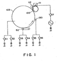
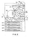
- the photosensitive drum 100 is uniformly charged (to -700 V, for example) to a predetermined polarity by a charger 111, and then, is exposed to a laser beam L.
- the first latent image for example, the latent image corresponding to the magenta color
- the photosensitive drum is developed in reverse by the magenta image developing device Dm, whereby the first toner image, that is, the magenta toner image, is formed on the photosensitive drum 100.
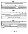
- the switch S3 connected to the transfer belt 50 is turned on to apply a positive bias to the transfer belt 50.
- the transfer belt 50 is placed in contact with the intermediary transfer drum 103.
- the transfer belt 50 is moved away from the intermediary transfer drum 103.
- the cleaning roller 130 is placed in contact with the intermediary transfer drum 103, and the switch S5 connected to the cleaning roller 130 is turned on to apply a positive bias, which is a bias having the polarity opposite to the normal polarity of the toner; to the cleaning roller 130.
- the transfer belt 50 and cleaning roller 130 which have been kept in contact with the intermediary transfer drum 103, are separated from the intermediary transfer drum 103, and then, the switch S3 and S5, which have been kept in the ON condition, are turned off. Thereafter, the switch S1 is turned off, and the switch S2 is turned on to apply a negative bias to the intermediary transfer drum 103, so that while the intermediary transfer drum 103 is rotated several times, the negatively charged untransferred toner on the intermediary transfer drum 103 is electrostatically transferred onto the photosensitive drum 100, and is removed by the cleaner 112.
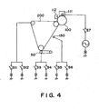
- Figure 4 is a schematic drawing of the image forming apparatus in the second embodiment of the present invention, depicting the general structure thereof.
- the configuration of the photosensitive member is not limited to a drum-like configuration; the photosensitive member may be in the form of a belt, for example.
- the electrode for charging the transferring means or the electrode for charging the residual toner may be in the modified form; for example, it may be in the form of a roller or a belt.
Landscapes
- Physics & Mathematics (AREA)
- General Physics & Mathematics (AREA)
- Electrostatic Charge, Transfer And Separation In Electrography (AREA)
Claims (7)
- Bilderzeugungsvorrichtung zur Erzeugung eines Tonerbilds auf einem Übertragungsmaterial (P) unter Verwendung eines Zwischenübertragungselements (103), mit:einem Bildtragelement (100);einer Tonerbilderzeugungseinrichtung (111, 107, 120) zum Erzeugen eines Tonerbilds auf dem Bildtragelement (100);einem Zwischenübertragungselement (103), das entlang einer endlosen Bahn in Kontakt mit dem Bildtragelement (100) beweglich ist;einer ersten Vorspannungsanlegeinrichtung (S1, S2) zum Erzeugen einer ersten Übertragungsvorspannung zwischen dem Bildtragelement (100) und dem Zwischenübertragungselement (103), um eine primäre Übertragung des Tonerbilds von dem Bildtragelement (100) auf das Zwischenübertragungselement (103) zu bewirken, an einer ersten Übertragungsposition des Zwischenübertragungselements (103);einer zweiten Vorspannungsanlegeinrichtung (S3, S4) zum Erzeugen einer zweiten Übertragungsvorspannung zwischen dem Zwischenübertragungselement (103) und einer Übertragungseinrichtung (50), um eine sekundäre Übertragung des Tonerbilds von dem Zwischenübertragungselement (103) auf das Übertragungsmaterial (P) zu bewirken, an einer zweiten Übertragungsposition des Zwischenübertragungselements (103);einer dritten Vorspannungsanlegeinrichtung (S5, S6) zum Anlegen einer Spannung an eine Elektrode (130) zum Aufladen von restlichem Toner, der an dem Zwischenübertragungselement (103) verbleibt, um den restlichen Toner nach der Übertragung zurück auf das Bildtragelement (100) zu übertragen;wobei die erste, die zweite und die dritte Vorspannungsanlegeinrichtung fähig sind zum Anlagen von Vorspannungsspannungen entgegengesetzter Polaritäten;wobei die Vorrichtung betriebsfähig ist in:einer ersten Reinigungsbetriebsart, in der der Toner, der nach der sekundären Übertragung auf dem Zwischenübertragungselement (103) verbleibt, durch die Elektrode auf eine zu einer normalen Polarität des Toners entgegengesetzte Polarität aufgeladen wird, durch die der restliche Toner während der primären Übertragung gleichzeitig mit der primären Übertragung zurück auf das Bildtragelement (100) übertragen wird, wodurch der restliche Toner von dem Zwischenübertragungselement (103) entfernt wird;einer zweiten Reinigungsbetriebsart, in der die Übertragungseinrichtung (50), wenn das Zwischenübertragungselement (103) das Bild nicht hat, durch die zweite Vorspannungsanlegeinrichtung mit einer Vorspannungsspannung versorgt wird, wodurch der an der Übertragungseinrichtung (50) abgelagerte Toner auf elektrostatische Weise zurück auf das Zwischenelement (103) übertragen wird; undeiner dritten Reinigungsbetriebsart, in der die Elektrode (130) zum Aufladen des restlichen Toners, wenn das Zwischenübertragungselement (103) das Bild nicht hat, durch die dritte Vorspannungsanlegeinrichtung mit einer Vorspannungsspannung versorgt wird, durch die der an der Elektrode (130) abgelagerte Toner auf elektrostatische Weise zurück auf das Zwischenübertragungselement (103) übertragen wird.
- Vorrichtung gemäß Anspruch 1, bei der das Bildtragelement (100) ein elektrofotografisches lichtempfindliches Element ist und der restliche Toner in der ersten Reinigungsbetriebsart durch eine Elektrode, die mit der dritten Vorspannungsanlegeinrichtung verbunden ist, um den restlichen Toner aufzuladen, auf eine Polarität aufgeladen wird, die entgegengesetzt zu seiner normalen Polarität ist.
- Vorrichtung gemäß Anspruch 2, bei der die Tonerbilder einer Vielzahl von Farbtonermaterialien sequenziell auf dem Zwischenübertragungselement (103) erzeugt werden und die Farbtonerbilder durch die Übertragungseinrichtung (50) alle zusammen auf das Übertragungsmaterial (P) übertragen werden.
- Vorrichtung gemäß Anspruch 1, bei der die erste, die zweite und die dritte Vorspannungsanlegeinrichtung alle Schalteinrichtungen (S1, S2, S3, S4, S5, S6) zum Anlegen von Spannungen mit einer positiven oder einer negativen Spannungslcomponente aufweisen.
- Vorrichtung gemäß Anspruch 4, bei der in den Reinigungsbetriebsarten:die erste Vorspannungsanlegeinrichtung eine derartige Vorspannungsspannung zum Übertragen des Toners von dem Zwischenübertragungselement (103) auf das Bildtragelement (100) anlegt;die zweite Vorspannungsanlegeinrichtung eine derartige Vorspannungsspannung zum Übertragen des Toners von der Übertragungseinrichtung (50) auf das Zwischenübertragungselement (103) anlegt; unddie dritte Vorspannungsanlegeinrichtung an die Elektrode (130) zum Aufladen des restlichen Toners eine Vorspannungsspannung zum gleichmäßigen Aufladen des Toners auf dem Zwischenübertragungselement (103) anlegt.
- Vorrichtung gemäß Anspruch 5, bei der die zweite Vorspannungsspannung an die Übertragungseinrichtung (50) angelegt wird, wenn in der Vorrichtung eine Stauung auftritt.
- Verfahren zum Erzeugen von Bildern auf einem Aufzeichnungsmedium, das ein Zuführen des Aufzeichnungsmediums an eine Vorrichtung gemäß einem der Ansprüche 1 bis 6 und ein Durchführen eines Betriebs der Vorrichtung umfasst.
Applications Claiming Priority (2)
| Application Number | Priority Date | Filing Date | Title |
|---|---|---|---|
| JP264096 | 1996-01-10 | ||
| JP2640/96 | 1996-01-10 |
Publications (3)
| Publication Number | Publication Date |
|---|---|
| EP0784246A2 EP0784246A2 (de) | 1997-07-16 |
| EP0784246A3 EP0784246A3 (de) | 1999-03-10 |
| EP0784246B1 true EP0784246B1 (de) | 2006-04-19 |
Family
ID=11534981
Family Applications (1)
| Application Number | Title | Priority Date | Filing Date |
|---|---|---|---|
| EP97300098A Expired - Lifetime EP0784246B1 (de) | 1996-01-10 | 1997-01-09 | Gerät zur Bilderzeugung unter Verwendung eines Zwischenübertragungselementes |
Country Status (3)
| Country | Link |
|---|---|
| US (1) | US5923939A (de) |
| EP (1) | EP0784246B1 (de) |
| DE (1) | DE69735690T2 (de) |
Families Citing this family (12)
| Publication number | Priority date | Publication date | Assignee | Title |
|---|---|---|---|---|
| JP3654560B2 (ja) * | 1997-08-18 | 2005-06-02 | 株式会社リコー | 画像形成装置 |
| TW510153B (en) * | 2001-05-09 | 2002-11-11 | Hannstar Display Corp | Low cross-section circuit apparatus for liquid crystal display module and manufacturing method of the same |
| JP4418689B2 (ja) * | 2004-02-04 | 2010-02-17 | キヤノン株式会社 | 画像形成装置 |
| JP2005221676A (ja) * | 2004-02-04 | 2005-08-18 | Canon Inc | 画像形成装置およびその制御方法 |
| JP4386262B2 (ja) * | 2004-02-04 | 2009-12-16 | キヤノン株式会社 | 画像形成装置 |
| JP2005221677A (ja) * | 2004-02-04 | 2005-08-18 | Canon Inc | 画像形成装置 |
| JP4371840B2 (ja) * | 2004-02-06 | 2009-11-25 | キヤノン株式会社 | シート処理装置及び画像形成装置 |
| US7228088B2 (en) * | 2005-01-21 | 2007-06-05 | Kabushiki Kaisha Toshiba | Color image forming apparatus and color image forming method |
| JP4372716B2 (ja) * | 2005-04-27 | 2009-11-25 | シャープ株式会社 | 転写装置および画像形成装置 |
| JP4760365B2 (ja) * | 2005-12-26 | 2011-08-31 | ブラザー工業株式会社 | 画像形成装置 |
| JP2008185989A (ja) * | 2007-01-31 | 2008-08-14 | Ricoh Co Ltd | 画像形成装置 |
| JP5590873B2 (ja) * | 2009-12-18 | 2014-09-17 | キヤノン株式会社 | 画像形成装置 |
Family Cites Families (28)
| Publication number | Priority date | Publication date | Assignee | Title |
|---|---|---|---|---|
| JPS5463838A (en) * | 1977-10-31 | 1979-05-23 | Ricoh Co Ltd | Method of cleaning trasfer roller of zerographic copying machine |
| JPS56153357A (en) * | 1980-04-29 | 1981-11-27 | Konishiroku Photo Ind Co Ltd | Copying device |
| US4461563A (en) * | 1982-10-22 | 1984-07-24 | Xerox Corporation | Copy sheet contamination prevention |
| JPH01105980A (ja) * | 1987-10-19 | 1989-04-24 | Sharp Corp | 残留物転写機構を有する画像形成装置 |
| CN1038277C (zh) * | 1987-12-28 | 1998-05-06 | 佳能公司 | 成象设备 |
| US5198863A (en) * | 1988-06-29 | 1993-03-30 | Canon Kabushiki Kaisha | Image forming apparatus |
| US5179397A (en) * | 1989-04-03 | 1993-01-12 | Canon Kabushiki Kaisha | Image forming apparatus with constant voltage and constant current control |
| JPH03102385A (ja) | 1989-09-18 | 1991-04-26 | Minolta Camera Co Ltd | クリーニング装置 |
| US5264902A (en) * | 1990-02-07 | 1993-11-23 | Canon Kabushiki Kaisha | Image forming device |
| US5173735A (en) * | 1990-06-07 | 1992-12-22 | Minolta Camera Kabushiki Kaisha | Image forming apparatus with improved cleaning operation |
| JPH04164226A (ja) | 1990-10-29 | 1992-06-09 | Eiken Kizai Kk | 液状検体細胞診検査用固定液 |
| US5079597A (en) * | 1990-12-24 | 1992-01-07 | Eastman Kodak Company | Cleaning method and apparatus for intermediate transfer member |
| JPH04296785A (ja) * | 1991-03-26 | 1992-10-21 | Canon Inc | 画像形成装置 |
| JPH04340564A (ja) * | 1991-05-16 | 1992-11-26 | Matsushita Electric Ind Co Ltd | カラー画像形成装置 |
| JP2840483B2 (ja) * | 1991-06-28 | 1998-12-24 | キヤノン株式会社 | 画像形成装置 |
| US5187526A (en) * | 1991-09-23 | 1993-02-16 | Eastman Kodak Company | Method and apparatus of forming a toner image on a receiving sheet using an intermediate image member |
| JPH05134560A (ja) | 1991-11-08 | 1993-05-28 | Mita Ind Co Ltd | 転写装置 |
| JP2945531B2 (ja) * | 1992-01-07 | 1999-09-06 | シャープ株式会社 | 画像形成装置 |
| JP3110539B2 (ja) * | 1992-02-17 | 2000-11-20 | キヤノン株式会社 | 画像形成装置 |
| JP3193113B2 (ja) * | 1992-04-21 | 2001-07-30 | 株式会社リコー | 画像形成方法 |
| JP3057121B2 (ja) * | 1992-04-28 | 2000-06-26 | 株式会社リコー | 画像形成装置 |
| JP3196329B2 (ja) * | 1992-05-29 | 2001-08-06 | キヤノン株式会社 | 画像形成装置 |
| US5438398A (en) * | 1992-05-29 | 1995-08-01 | Canon Kabushiki Kaisha | Image forming apparatus with intermediate transfer member |
| NL9201348A (nl) * | 1992-07-27 | 1994-02-16 | Oce Nederland Bv | Inrichting voor het overdragen van een tonerbeeld van een beeldvormingsmedium naar een ontvangstmateriaal. |
| JPH0660569A (ja) | 1992-08-05 | 1994-03-04 | Hitachi Ltd | 磁気ディスク装置 |
| JPH0777879A (ja) * | 1993-09-07 | 1995-03-20 | Canon Inc | 画像形成装置 |
| US5485256A (en) * | 1994-01-12 | 1996-01-16 | Eastman Kodak Company | Method and apparatus for forming combined toner images |
| US5565975A (en) * | 1994-06-10 | 1996-10-15 | Matsushita Electric Industrial Co., Ltd. | Color image forming apparatus and method having toner images transferred to a paper sheet |
-
1997
- 1997-01-09 EP EP97300098A patent/EP0784246B1/de not_active Expired - Lifetime
- 1997-01-09 DE DE69735690T patent/DE69735690T2/de not_active Expired - Lifetime
- 1997-01-09 US US08/780,813 patent/US5923939A/en not_active Expired - Lifetime
Also Published As
| Publication number | Publication date |
|---|---|
| US5923939A (en) | 1999-07-13 |
| EP0784246A3 (de) | 1999-03-10 |
| DE69735690D1 (de) | 2006-05-24 |
| DE69735690T2 (de) | 2006-11-02 |
| EP0784246A2 (de) | 1997-07-16 |
| HK1001425A1 (en) | 1998-06-19 |
Similar Documents
| Publication | Publication Date | Title |
|---|---|---|
| EP0401977B1 (de) | Bilderzeugungsgerät | |
| EP0298505B1 (de) | Bilderzeugungsgerät | |
| KR20080073670A (ko) | 화상 담지 부재 상으로 전사 잔류 토너를 전사하는 화상형성 장치 | |
| US5287144A (en) | Image forming apparatus having transfer charger which is controlled according to ambient conditions | |
| US5923939A (en) | Image forming apparatus employing intermediary transfer member | |
| EP1262840B1 (de) | Bilderzeugungsgerät mit einer Entladungsvorrichtung zur Vermeidung der Wiederbefestigung von Resttoner auf einem Zwischenübertragungselement | |
| US5079597A (en) | Cleaning method and apparatus for intermediate transfer member | |
| US6721515B2 (en) | Electrostatic transfer type image forming apparatus with control of start timing of transfer output | |
| KR100305164B1 (ko) | 중간전사부재를갖춘화상형성장치 | |
| JP3461215B2 (ja) | 画像形成装置 | |
| HK1001425B (en) | Image forming apparatus employing intermediary transfer member | |
| JP2872691B2 (ja) | カラー画像形成装置 | |
| JP3573335B2 (ja) | クリーニング装置 | |
| JP3277721B2 (ja) | 画像形成装置 | |
| JP4580099B2 (ja) | 画像形成装置 | |
| JP2780266B2 (ja) | 画像形成方法 | |
| JP3256938B2 (ja) | 画像形成装置 | |
| JPH09251249A (ja) | 中間転写体を採用した画像形成装置 | |
| JP2000242091A (ja) | 画像形成装置 | |
| JPH05341670A (ja) | 中間転写装置 | |
| JPH10282814A (ja) | 転写装置 | |
| JPH05142955A (ja) | 電子写真記録装置 | |
| JPH03214182A (ja) | 画像形成装置 | |
| JPH04296784A (ja) | 画像形成装置 | |
| JPH04296774A (ja) | 画像形成装置 |
Legal Events
| Date | Code | Title | Description |
|---|---|---|---|
| PUAI | Public reference made under article 153(3) epc to a published international application that has entered the european phase |
Free format text: ORIGINAL CODE: 0009012 |
|
| AK | Designated contracting states |
Kind code of ref document: A2 Designated state(s): DE FR GB IT |
|
| PUAL | Search report despatched |
Free format text: ORIGINAL CODE: 0009013 |
|
| AK | Designated contracting states |
Kind code of ref document: A3 Designated state(s): DE FR GB IT |
|
| 17P | Request for examination filed |
Effective date: 19990721 |
|
| 17Q | First examination report despatched |
Effective date: 20010919 |
|
| GRAP | Despatch of communication of intention to grant a patent |
Free format text: ORIGINAL CODE: EPIDOSNIGR1 |
|
| GRAS | Grant fee paid |
Free format text: ORIGINAL CODE: EPIDOSNIGR3 |
|
| GRAA | (expected) grant |
Free format text: ORIGINAL CODE: 0009210 |
|
| AK | Designated contracting states |
Kind code of ref document: B1 Designated state(s): DE FR GB IT |
|
| PG25 | Lapsed in a contracting state [announced via postgrant information from national office to epo] |
Ref country code: IT Free format text: LAPSE BECAUSE OF FAILURE TO SUBMIT A TRANSLATION OF THE DESCRIPTION OR TO PAY THE FEE WITHIN THE PRESCRIBED TIME-LIMIT;WARNING: LAPSES OF ITALIAN PATENTS WITH EFFECTIVE DATE BEFORE 2007 MAY HAVE OCCURRED AT ANY TIME BEFORE 2007. THE CORRECT EFFECTIVE DATE MAY BE DIFFERENT FROM THE ONE RECORDED. Effective date: 20060419 |
|
| REG | Reference to a national code |
Ref country code: GB Ref legal event code: FG4D |
|
| REF | Corresponds to: |
Ref document number: 69735690 Country of ref document: DE Date of ref document: 20060524 Kind code of ref document: P |
|
| REG | Reference to a national code |
Ref country code: HK Ref legal event code: GR Ref document number: 1001425 Country of ref document: HK |
|
| ET | Fr: translation filed | ||
| PLBE | No opposition filed within time limit |
Free format text: ORIGINAL CODE: 0009261 |
|
| STAA | Information on the status of an ep patent application or granted ep patent |
Free format text: STATUS: NO OPPOSITION FILED WITHIN TIME LIMIT |
|
| 26N | No opposition filed |
Effective date: 20070122 |
|
| PGFP | Annual fee paid to national office [announced via postgrant information from national office to epo] |
Ref country code: IT Payment date: 20070611 Year of fee payment: 11 |
|
| PGFP | Annual fee paid to national office [announced via postgrant information from national office to epo] |
Ref country code: FR Payment date: 20070123 Year of fee payment: 11 |
|
| REG | Reference to a national code |
Ref country code: FR Ref legal event code: ST Effective date: 20081029 |
|
| PG25 | Lapsed in a contracting state [announced via postgrant information from national office to epo] |
Ref country code: FR Free format text: LAPSE BECAUSE OF NON-PAYMENT OF DUE FEES Effective date: 20080131 |
|
| PG25 | Lapsed in a contracting state [announced via postgrant information from national office to epo] |
Ref country code: IT Free format text: LAPSE BECAUSE OF NON-PAYMENT OF DUE FEES Effective date: 20080109 |
|
| PGFP | Annual fee paid to national office [announced via postgrant information from national office to epo] |
Ref country code: DE Payment date: 20150131 Year of fee payment: 19 |
|
| PGFP | Annual fee paid to national office [announced via postgrant information from national office to epo] |
Ref country code: GB Payment date: 20150123 Year of fee payment: 19 |
|
| REG | Reference to a national code |
Ref country code: DE Ref legal event code: R119 Ref document number: 69735690 Country of ref document: DE |
|
| GBPC | Gb: european patent ceased through non-payment of renewal fee |
Effective date: 20160109 |
|
| PG25 | Lapsed in a contracting state [announced via postgrant information from national office to epo] |
Ref country code: GB Free format text: LAPSE BECAUSE OF NON-PAYMENT OF DUE FEES Effective date: 20160109 Ref country code: DE Free format text: LAPSE BECAUSE OF NON-PAYMENT OF DUE FEES Effective date: 20160802 |