EP0786328A2 - Dispositif pour retenir une tringle de talon pourvue d'un élément de remplissage - Google Patents
Dispositif pour retenir une tringle de talon pourvue d'un élément de remplissage Download PDFInfo
- Publication number
- EP0786328A2 EP0786328A2 EP97300412A EP97300412A EP0786328A2 EP 0786328 A2 EP0786328 A2 EP 0786328A2 EP 97300412 A EP97300412 A EP 97300412A EP 97300412 A EP97300412 A EP 97300412A EP 0786328 A2 EP0786328 A2 EP 0786328A2
- Authority
- EP
- European Patent Office
- Prior art keywords
- ring body
- radial direction
- extending
- retaining
- swing
- Prior art date
- Legal status (The legal status is an assumption and is not a legal conclusion. Google has not performed a legal analysis and makes no representation as to the accuracy of the status listed.)
- Withdrawn
Links
Images

Classifications
-
- B—PERFORMING OPERATIONS; TRANSPORTING
- B29—WORKING OF PLASTICS; WORKING OF SUBSTANCES IN A PLASTIC STATE IN GENERAL
- B29D—PRODUCING PARTICULAR ARTICLES FROM PLASTICS OR FROM SUBSTANCES IN A PLASTIC STATE
- B29D30/00—Producing pneumatic or solid tyres or parts thereof
- B29D30/06—Pneumatic tyres or parts thereof (e.g. produced by casting, moulding, compression moulding, injection moulding, centrifugal casting)
- B29D30/08—Building tyres
- B29D30/20—Building tyres by the flat-tyre method, i.e. building on cylindrical drums
- B29D30/32—Fitting the bead-rings or bead-cores; Folding the textile layers around the rings or cores
-
- B—PERFORMING OPERATIONS; TRANSPORTING
- B29—WORKING OF PLASTICS; WORKING OF SUBSTANCES IN A PLASTIC STATE IN GENERAL
- B29D—PRODUCING PARTICULAR ARTICLES FROM PLASTICS OR FROM SUBSTANCES IN A PLASTIC STATE
- B29D30/00—Producing pneumatic or solid tyres or parts thereof
- B29D30/06—Pneumatic tyres or parts thereof (e.g. produced by casting, moulding, compression moulding, injection moulding, centrifugal casting)
- B29D30/08—Building tyres
- B29D30/20—Building tyres by the flat-tyre method, i.e. building on cylindrical drums
- B29D30/24—Drums
- B29D30/26—Accessories or details, e.g. membranes, transfer rings
- B29D30/2607—Devices for transferring annular tyre components during the building-up stage, e.g. from the first stage to the second stage building drum
-
- B—PERFORMING OPERATIONS; TRANSPORTING
- B29—WORKING OF PLASTICS; WORKING OF SUBSTANCES IN A PLASTIC STATE IN GENERAL
- B29D—PRODUCING PARTICULAR ARTICLES FROM PLASTICS OR FROM SUBSTANCES IN A PLASTIC STATE
- B29D30/00—Producing pneumatic or solid tyres or parts thereof
- B29D30/06—Pneumatic tyres or parts thereof (e.g. produced by casting, moulding, compression moulding, injection moulding, centrifugal casting)
- B29D30/08—Building tyres
- B29D30/20—Building tyres by the flat-tyre method, i.e. building on cylindrical drums
- B29D30/32—Fitting the bead-rings or bead-cores; Folding the textile layers around the rings or cores
- B29D2030/3207—Positioning the beads
Definitions
- the present invention relates to a mechanism for retaining a bead with a filler.
- each of the extending/retracting means includes a linear guide which is mounted to the ring body and a movable rod which is movably supported by the linear guide in the radial direction of the ring body, and the radially extending line thereof intersects the central axis of the ring body, with the
- the movable rod of each of the extending/ retracting means is moved by the driving means inwardly in the radial direction of the ring body. Accordingly, the retaining bodies reach the predetermined positions in the radial direction of the ring body and all of the arc-shaped retaining bodies are positioned on the same circle which centers around the central axis of the ring body. Thereafter, a bead with a filler is supplied to and retained by the retaining body. Then, the bead with the filler retained as such is delivered from the retaining body to a tire forming drum.
- the movable rod of each of the extending/ retracting means is moved by the driving means outwardly in the radial direction of the ring body.
- the retaining body is moved further outward in the radial direction of the ring body than the outer end of the filler in the radial direction thereof.
- An object of the present invention is to provide a mechanism for retaining a bead with a filler which is small, inexpensive, and in which maintenance of accuracy can be simplified.
- a mechanism for maintaining a bead with a filler comprising: a ring body; a plurality of extending/ retracting means which are separately provided at the ring body in the circumferential direction of said ring body; an arc-shaped retaining body which is provided at each of the plurality of said extending/retracting means and which can retain a bead with a filler; and driving means which applies driving force to said extending/ retracting means and synchronously operates said extending/retracting means so as to move and extend/retract said retaining body in the radial direction of the ring body, said extending/retracting means further including: a pair of parallel links separated in the radial direction of the ring body and disposed parallel to each other, and the base end portions of the parallel links being rotatably connected to said ring body; and a connecting link which is rotatably connected to the distal end portions of said pair of parallel links,
- a mechanism for maintaining a bead with a filler comprising: a ring body; a plurality of extending/ retracting means which are separately provided at the ring body in the circumferential direction of said ring body; an arc-shaped retaining body which is provided at each of the plurality of said extending/ retracting means and which can retain a bead with a filler; and driving means which applies driving force to said extending/ retracting means and synchronously operates said extending/retracting means so as to move and extend/retract said retaining body in the radial direction of the ring body, said extending/ retracting means further including: a pair of swing links separated in the radial direction of the ring body and disposed substantially parallel to each other, and the base end portions of the swing links being rotatably connected to said ring body; and a connecting link which is rotatably connected to the distal end portions of said pair of swing links, and said retaining body being provided at the inner end portion of the connecting link wherein
- a mechanism for maintaining a bead with a filler comprising: a ring body; a plurality of extending/ retracting means which are separately provided at the ring body in the circumferential direction of said ring body; an arc-shaped retaining body which is provided at each of the plurality of said extending/ retracting means and which can retain a bead with a filler; and driving means which applies driving force to said extending/retracting means and synchronously operates said extending/retracting means so as to move and extend/retract said retaining body in the radial direction of the ring body, said extending/retracting means further including: a pair of swing links separately disposed in the radial direction of the ring body, and the base end portions of the swing links being rotatably connected to said ring body; and a connecting link which is rotatably connected to the distal end portions of said pair of swing links, and said retaining body being provided at the inner end portion of the connecting link wherein, among said swing
- each of the retaining bodies reaches the predetermined position in the radial direction of the ring body, and all of the arc-shaped retaining bodies are positioned on the same circle, which centers around the central axis of the ring body and which has the predetermined radius.
- the bead with the filler having the predetermined radius can be retained. In this state, the bead with the filler having the predetermined radius is supplied to and retained by the retaining body.
- the retaining body retains the bead with the filler (when the retaining body is positioned at the predetermined position in the radial direction of the ring body), these arc-shaped retaining bodies are positioned so as to superpose on the same circle having a predetermined radius, i.e., so as to superpose on the bead correctly.
- the retention is thereby reliably effected.
- the retaining bodies deviate from the predetermined positions in the radial direction of the ring body to any positions in the radial direction thereof, these retaining bodies are not correctly superposed on the bead and are superposed on the bead in a slightly inclined state. The retention may be insufficient.
- the connecting link extends to the radial direction outer side further than the area which connects the connecting link and the parallel link positioned at the radial direction outer side. Therefore, it is possible to prevent the case in which the connecting link protrudes from the ring body to the radial direction outer side.
- the entire retaining mechanism can be made compact.
- the connecting link when the retaining body moves from the predetermined position in the radial direction of the ring body to the radial direction outer side and the extending line of the connecting link moves away from the central axis of the ring body, as the connecting link is influenced by the difference between the length of the swing link positioned at the radial direction outer side and the length of the swing link positioned at the radial direction inner side, the connecting link inclines so that the extending line of the connecting link approaches the central axis of the ring body.
- Fig. 1 is a schematic elevational view illustrating a first embodiment of the present invention.
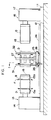
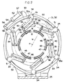
- Fig. 2 is a cross sectional view, taken along line I-I in Fig. 1.
- Fig. 3 is a perspective view, in which the portion of a vicinity of a retaining body is broken.
- Fig. 4 is a partial side view illustrating a second embodiment of the present invention.
- a base 1 1 is disposed on a floor surface 12.
- a tire forming device 13 is disposed at one end portion of the base 11.
- the tire forming device 13 includes a driving portion 14 and a tire forming drum 15, which is provided at the other side (i.e., the righthand side) of the driving portion 14 and is driven and rotated by the driving portion 14.
- Bead supporting portions 15a, 15b, which are movable in the radial direction of the tire forming drum 15, are disposed at the axial direction end portions of the tire forming drum 15.
- a band forming device 16 is provided at the other end portion of the base 11.
- the band forming device 16 includes a driving portion 17 and an extendible/retractable band forming drum 18 which is provided at one side (i.e., the left-hand side) of the driving portion 17 and is driven and rotated by the driving portion 17.
- the band forming drum 18 is coaxial with the above-described tire forming drum 15.
- a tire forming material e.g., carcass ply
- the tire forming material is wound around the periphery of the band forming drum 18 so as to form a cylindrical band D.
- a pair of guide rails 24 are placed on the base 1 1 and extend parallel to the axis of the tire forming drum 15.
- the movable frame 25 moves along the axis of the band D while being guided by the guide rails 24.
- Retaining mechanisms 31, 32 are respectively provided at one end portion of the movable frame 25 and the other end portion thereof.
- Each of the retaining mechanisms 31, 32 is coaxial with the axis of the tire forming drum 15 and includes a ring body 33 which stands upright having an internal radius larger than that of the band D.
- a plurality of (here, six) extending/retracting means 34 are provided at the ring body 33 at equal intervals in the circumferential direction thereof.
- Each of the extending/ retracting means 34 includes a pair of parallel links 35, 36 whose base end portions are rotatably connected to the ring body 33 via pins 37, 38. These parallel links 35, 36 are separated in the radial direction of the ring body 33 and are disposed parallel to each other.
- a connecting link 39 rotatably connects the distal end portions of the parallel links 35, 36 via pins 40, 41 and extend substantially in the radial direction of the ring body 33.
- the radial direction outer end of the connecting link 39 ends at the distal end of the parallel link 35 and does not project further than the radial direction outer side.
- a distance L i.e., the length L of the parallel link 35, is a distance between a point (the central axis of the pin 40) which connects the connecting link 39 and the parallel link 35 and a point (the central axis of the pin 37) which connects the parallel link 35 and the ring body 33.
- a distance M i.e., the length M of the parallel link 36, is a distance between a point (the central axis of the pin 41) which connects the connecting link 39 and the parallel link 36 and a point (the central axis of the pin 38) which connects the parallel link 36 and the ring body 33.
- the distance L is equal to the distance M.
- a line which connects the central axes of the pins 40, 41 is parallel to a line which connects the central axes of the pins 37, 38.
- the extending line N slightly deviates in the circumferential direction of the ring body 33 due to the swings of the parallel links 35, 36, only when the parallel links 35, 36 form a predetermined inclined angle with respect to the radial direction of the ring body 33, the extending line N practically intersects the central axis P of the ring body 33.
- a substantially triangular connecting portion 35a is integrally formed at the base end portion of the parallel link 35.
- An arc-shaped retaining body 45 which extends substantially along a ring body 33, is removably mounted to each of the extending/ retracting means 34, more specifically, to the inner end portion of the connecting link 39 in the radial direction of the ring body 33.
- the radius of curvature of the retaining body 45 is equal to the distance between the central axis P and the point at which the retaining body 45 is positioned.
- all of the retaining bodies 45 are positioned (superposed) on the same circle which centers around the central axis P of the ring body 33 and which has a predetermined radius.
- a plurality of accommodating holes 46 are respectively formed on the side surface (end surface) of the retaining body 45 at equal intervals in the circumferential direction thereof.
- a permanent magnet 47 which attracts and retains a bead B with a filler F, is accommodated and fixed to the respective accommodating holes 46.
- the retaining body 45 is replaced with the one having the radius of curvature in accordance with the bead B.
- An arc-shaped connecting rod 50 connects the extending/retracting means 34.
- the both ends of the connecting rod 50 are rotatably connected to the connecting portions 35a of the adjacent parallel links 35 via pins 51.
- the head side of a cylinder 52 is rotatably connected to the ring body 33 via a bracket 53.
- a transmitting arm 55 which is fixed to the pin 37 of any of the extending/retracting means 34, is rotatably connected to the distal end of a piston rod 54 of the cylinder 52.
- the formed cylindrical band D is supported on the band forming drum 18 of the band forming device 16, and that a formed green tire is supported on the tire forming drum 15 of the tire forming device 13.
- the movable frame 25 waits between the band forming drum 18 and the tire forming drum 15.
- the beads B with the fillers F are respectively delivered to and held at the holding mechanisms 31, 32.
- the cylinder 52 of the holding mechanisms 31, 32 is operated so as to project the piston rod 54, and the driving force from the cylinder 52 is applied to each of the extending/retracting means 34 via the connecting rod 50.
- the parallel links 35, 36 of the extending/ retracting means 34 maintain a parallel relationship
- the parallel links 35, 36 swing around the base end portions, i.e., the pins 37, 38, from the position shown by an imaginary line in Fig. 2 to the radial direction inner side.
- the parallel links 35, 36 synchronize with the connecting link 39 and are moved to the radial direction inner side.
- the base end portions of the parallel links 35, 36 are rotatably connected to the ring body 33 via the pins 37, 38, the extending line N of the connecting link 39 deviates in the circumferential direction of the ring body 33 due to the swings of the aforementioned parallel links 35, 36.
- the extending line N gradually moves away from the central axis P of the ring body 33, and thereafter, the extending line N gradually moves closer to the central axis P thereof.
- the retaining body 45 moves in the radial direction of the ring body 33 in this way, the retaining body 45 slightly deviates in the circumferential direction (transverse direction) of the ring body 33. At this time, because the retaining body 45 does not retain the bead B with the filler F, the problem does not occur.
- each of the retaining bodies 45 reaches a predetermined position in the radial direction shown by a solid line in Fig. 2.
- all of the arc-shaped retaining bodies 45 are positioned(superposed) on the same circle which centers around the central axis P and has a predetermined radius.
- the bead B with the filler F having the predetermined radius can be retained by the retaining body 45.
- the bead B with the filler F having the predetermined radius is supplied to and retained by each of the retaining bodies 45.
- the moving means is operated.
- the movable frame 25, the band retaining mechanism 27, and the retaining mechanisms 31, 32 are integrally moved to the other side.
- the band retaining mechanism 27 reaches the predetermined position of the band D in the outer side thereof (the position at which the center of the band retaining mechanism 27 coincides with the axial direction center of the band D)
- the above movement is stopped.
- the band D is retained from the outer side thereof by the band retaining mechanism 27 and the radius of the band forming drum 18 is decreased.
- the band D is delivered from the band forming drum 18 to the band retaining mechanism 27.
- the bead supporting portions 15a, 15b of the tire forming drum 15 are moved to the radial direction inner side and the retention of the formed green tire is released.
- the released green tire is conveyed by an unillustrated conveying device.
- the moving means is operated again.
- the movable frame 25, the band retaining mechanism 27 which retains the band D, and the retaining mechanisms 31, 32 which retain the beads B with the fillers F are integrally moved to one side.
- the band D reaches the predetermined position (the position at which the axial direction center of the band D coincides with the axial direction center of the tire forming drum 15 and at which the beads B with the fillers F superpose the bead supporting portions 15a, 15b)
- the above movement is stopped.
- the bead supporting portions 15a, 15b are moved to the radial direction outer side (the radii thereof are increased) and the beads B with the fillers F are retained from the inner sides thereof via the band D.
- the beads B with the fillers F are set to predetermined positions on the band D.
- the cylinder 52 of the retaining mechanisms 31, 32 is operated so as to withdraw the piston rod 54.
- the parallel links 35, 36 of the extending/retracting means 34 synchronously swing to the radial direction outer side, and the retaining body 45 is removed from the bead B with the filler F.
- the band retaining mechanism 27 is also removed from the band D. Consequently, the band D and the bead B with the filler F are delivered to the tire forming drum 15 from the band retaining mechanism 27 and the retaining mechanisms 31, 32.
- the connecting link 39 does not extend to the radial direction outer side further than the area which connects the parallel link 35, which is positioned at the radial direction outer side, and the connecting link 39 (the connecting link 39 ends at the above-described connecting area). Accordingly, even if the connecting link 39 moves to the outermost side in the radial direction, the connecting link 39 can not protrude from the ring body 33 and the connecting rod 50 to the radial direction outer side. Thus, the entire retaining mechanisms 31, 32 can be made compact.
- the retaining body 45 in the radial direction of the ring body 33 is effected by the swings of the parallel links 35, 36, it is not necessary to use an expensive linear guide. Further, because the swinging resistance of the parallel links is remarkably smaller than the sliding resistance of a linear guide, it suffices if the driving means which is small, inexpensive, and which generates small driving force is used (here, the cylinder 52 is used). Moreover, at this time, since the driving means is used only for swinging the parallel links 35, 36, the retaining mechanisms 31, 32 can be smoothly operated for a long period of time in a state in which the necessary accuracy is maintained in a simple way. Accordingly, the maintenance of the accuracy of the retaining mechanisms 31, 32 can be simplified.
- the moving means is operated.
- the movable frame 25, the band retaining mechanism 27 which is empty, and the retaining mechanisms 31, 32 are integrally moved to the other side and returned to the initial standby positions.
- the retaining bodies 45 of the retaining mechanisms 31, 32 are withdrawn by a large amount from the predetermined positions in the radial direction of the ring body 33, at which the beads B with the fillers F are retained as mentioned above, to the radial direction outer side, the retaining bodies 45 do not contact the fillers F.
- the tire forming member is supplied to and wound around the periphery of the band forming drum 18 so as to form the band D.
- the tire forming device 13 while the bead supporting portions 15a, 15b are approached to each other, air is injected into the band D between the beads B with the fillers F so as to deform the band D between the beads B with the fillers F into a troidal shape.
- Fig. 4 illustrates the second embodiment of the present invention.
- a pair of swing links 59, 60 are used which are substantially parallel to each other and in which the length Q of the link 59 positioned at the radial direction outer side is slightly longer than the length R of the link 60 positioned at the radial direction inner side.
- the swing links 59, 60 swing outwardly in the radial direction of the ring body 33, the retaining body 45 moves from the predetermined position in the radial direction of the ring body 33 to the radial direction outer side, and the extending line N of the connecting link 39 deviates from the central axis P of the ring body 33.
- the connecting link 39 is influenced by the difference between the length Q of the swing link 59 positioned at the radial direction outer side and the length R of the swing link 60 positioned at the radial direction inner side, the connecting link 39 inclines so that the extending line N of the connecting link 39 approaches the central axis P of the ring body 33. Accordingly, these movements offset each other, and the extending line N of the connecting link 39 practically intersects the central axis P of the ring body 33 from the predetermined position at which the retaining body 45 is placed in the radial direction of the ring body 33 to the position at the radial direction outer side which is slightly away from the predetermined position.
- a pair of swing links are used in which the length Q of the link positioned at the radial direction outer side is slightly shorter than the length R of the link positioned at the radial direction inner side and, for example, as from the base ends to the distal ends thereof, the distance between the links become narrow.
- the two movements offset each other, and the beads with the fillers having slightly different radii can be retained.
- the present invention provides a mechanism for retaining a bead with a filler which can be small, inexpensive, and in which maintenance of accuracy can be simplified.
Landscapes
- Engineering & Computer Science (AREA)
- Mechanical Engineering (AREA)
- Tyre Moulding (AREA)
Applications Claiming Priority (2)
| Application Number | Priority Date | Filing Date | Title |
|---|---|---|---|
| JP31270/96 | 1996-01-25 | ||
| JP8031270A JPH09201883A (ja) | 1996-01-25 | 1996-01-25 | フィラー付きビードの保持機構 |
Publications (2)
| Publication Number | Publication Date |
|---|---|
| EP0786328A2 true EP0786328A2 (fr) | 1997-07-30 |
| EP0786328A3 EP0786328A3 (fr) | 1997-12-29 |
Family
ID=12326651
Family Applications (1)
| Application Number | Title | Priority Date | Filing Date |
|---|---|---|---|
| EP97300412A Withdrawn EP0786328A3 (fr) | 1996-01-25 | 1997-01-23 | Dispositif pour retenir une tringle de talon pourvue d'un élément de remplissage |
Country Status (3)
| Country | Link |
|---|---|
| US (1) | US5858165A (fr) |
| EP (1) | EP0786328A3 (fr) |
| JP (1) | JPH09201883A (fr) |
Cited By (8)
| Publication number | Priority date | Publication date | Assignee | Title |
|---|---|---|---|---|
| WO2012093007A1 (fr) * | 2011-01-04 | 2012-07-12 | Continental Reifen Deutschland Gmbh | Procédé de fabrication d'une ébauche de pneu |
| CN107498901A (zh) * | 2017-09-22 | 2017-12-22 | 青岛软控机电工程有限公司 | 一种带束层传递环 |
| WO2021110364A1 (fr) * | 2019-12-02 | 2021-06-10 | Vmi Holland B.V. | Élément de retenue de cordon |
| US11807741B2 (en) | 2015-06-30 | 2023-11-07 | BiologiQ, Inc. | Articles formed with renewable green plastic materials and starch-based polymeric materials lending increased biodegradability |
| US11840623B2 (en) | 2015-06-30 | 2023-12-12 | BiologiQ, Inc. | Methods for lending biodegradability to non-biodegradable polyolefin and nylon materials |
| US11879058B2 (en) | 2015-06-30 | 2024-01-23 | Biologiq, Inc | Yarn materials and fibers including starch-based polymeric materials |
| US11926940B2 (en) | 2015-06-30 | 2024-03-12 | BiologiQ, Inc. | Spunbond nonwoven materials and fibers including starch-based polymeric materials |
| US11926929B2 (en) | 2015-06-30 | 2024-03-12 | Biologiq, Inc | Melt blown nonwoven materials and fibers including starch-based polymeric materials |
Families Citing this family (12)
| Publication number | Priority date | Publication date | Assignee | Title |
|---|---|---|---|---|
| JP3808603B2 (ja) * | 1997-09-17 | 2006-08-16 | 株式会社ブリヂストン | ビードフィラー付きビードの自動供給装置 |
| US6623583B2 (en) | 2001-06-05 | 2003-09-23 | The Goodyear Tire And Rubber Company | Bead holder |
| WO2003061954A1 (fr) * | 2001-12-27 | 2003-07-31 | Gian Luigi Bosio | Appareil de montage de pneumatiques |
| JP4188756B2 (ja) * | 2003-05-29 | 2008-11-26 | 横浜ゴム株式会社 | 物品把持装置 |
| DE102004032511A1 (de) * | 2004-07-06 | 2006-02-16 | Continental Aktiengesellschaft | Verfahren und Vorrichtung zum Positionieren von Wulstkernen |
| JP4748448B2 (ja) * | 2005-12-26 | 2011-08-17 | 横浜ゴム株式会社 | ビード保持装置の傾倒検知装置 |
| JP5025256B2 (ja) * | 2006-12-27 | 2012-09-12 | 株式会社ブリヂストン | 円筒状ゴム部材の処理方法および装置 |
| US20080247416A1 (en) * | 2007-04-04 | 2008-10-09 | Finisar Corporation | Circuit for tapping a line in a network diagnostic component |
| US7841634B2 (en) * | 2007-12-20 | 2010-11-30 | Mcneil & Nrm, Inc. | Tire loader basket |
| US9616628B2 (en) * | 2008-07-23 | 2017-04-11 | Pirelli Tyre S.P.A. | Apparatus and process for manufacturing tyres for vehicle wheels |
| US9701083B2 (en) * | 2008-07-23 | 2017-07-11 | Pirelli Tyre S.P.A. | Process and apparatus for manufacturing tyres for vehicle wheels |
| CN102205581B (zh) * | 2009-07-03 | 2013-09-18 | 江苏华瑞重工机械有限公司 | 机械手抓胎器 |
Family Cites Families (10)
| Publication number | Priority date | Publication date | Assignee | Title |
|---|---|---|---|---|
| US4105486A (en) * | 1977-03-30 | 1978-08-08 | Nrm Corporation | Tire component transfer |
| SU852632A1 (ru) * | 1979-12-07 | 1981-08-07 | Всесоюзный Научно-Исследовательскийи Конструкторский Институт Пооборудованию Для Шинной Промышленности | Устройство дл захвата и транспорти-РОВАНи КОльцЕВыХ зАгОТОВОК пОКРышЕКпНЕВМАТичЕСКиХ шиН |
| JPS57174236A (en) * | 1981-04-20 | 1982-10-26 | Mitsubishi Heavy Ind Ltd | Feeder for tire molding machine |
| ES2044079T3 (es) * | 1988-01-25 | 1994-01-01 | Bridgestone Corp | Aparato de transporte de miembros cilindricos y maquina de fabricacionde neumaticos. |
| JP2539657B2 (ja) * | 1988-01-25 | 1996-10-02 | 株式会社ブリヂストン | 円筒状部材の搬送装置 |
| JPH01255528A (ja) * | 1988-04-06 | 1989-10-12 | Mitsubishi Heavy Ind Ltd | タイヤ製造装置におけるバンドトランスフア |
| US4964931A (en) * | 1989-04-04 | 1990-10-23 | The Goodyear Tire & Rubber Company | Tire bead setter apparatus and method |
| JP2810114B2 (ja) * | 1989-06-03 | 1998-10-15 | 株式会社ブリヂストン | タイヤ成型装置 |
| JP2691066B2 (ja) * | 1990-10-02 | 1997-12-17 | 三菱重工業株式会社 | 真空吸着を用いたバンド搬送装置 |
| US5441587A (en) * | 1994-08-12 | 1995-08-15 | Wyko, Inc. | Transfer ring having selective adjustability of shoe movement |
-
1996
- 1996-01-25 JP JP8031270A patent/JPH09201883A/ja not_active Withdrawn
-
1997
- 1997-01-23 US US08/786,902 patent/US5858165A/en not_active Expired - Lifetime
- 1997-01-23 EP EP97300412A patent/EP0786328A3/fr not_active Withdrawn
Cited By (13)
| Publication number | Priority date | Publication date | Assignee | Title |
|---|---|---|---|---|
| WO2012093007A1 (fr) * | 2011-01-04 | 2012-07-12 | Continental Reifen Deutschland Gmbh | Procédé de fabrication d'une ébauche de pneu |
| US11807741B2 (en) | 2015-06-30 | 2023-11-07 | BiologiQ, Inc. | Articles formed with renewable green plastic materials and starch-based polymeric materials lending increased biodegradability |
| US11926929B2 (en) | 2015-06-30 | 2024-03-12 | Biologiq, Inc | Melt blown nonwoven materials and fibers including starch-based polymeric materials |
| US11926940B2 (en) | 2015-06-30 | 2024-03-12 | BiologiQ, Inc. | Spunbond nonwoven materials and fibers including starch-based polymeric materials |
| US11879058B2 (en) | 2015-06-30 | 2024-01-23 | Biologiq, Inc | Yarn materials and fibers including starch-based polymeric materials |
| US11840623B2 (en) | 2015-06-30 | 2023-12-12 | BiologiQ, Inc. | Methods for lending biodegradability to non-biodegradable polyolefin and nylon materials |
| CN107498901A (zh) * | 2017-09-22 | 2017-12-22 | 青岛软控机电工程有限公司 | 一种带束层传递环 |
| CN107498901B (zh) * | 2017-09-22 | 2023-05-09 | 青岛软控机电工程有限公司 | 一种带束层传递环 |
| CN112976628A (zh) * | 2019-12-02 | 2021-06-18 | Vmi荷兰公司 | 胎圈保持构件、胎圈保持设备与胎圈操纵组件 |
| US11752718B2 (en) | 2019-12-02 | 2023-09-12 | Vmi Holland B.V. | Bead retaining member, bead retaining device and bead handling assembly |
| CN112976628B (zh) * | 2019-12-02 | 2023-06-27 | Vmi荷兰公司 | 胎圈保持构件、胎圈保持设备与胎圈操纵组件 |
| NL2024349B1 (en) * | 2019-12-02 | 2021-08-31 | Vmi Holland Bv | Bead retaining member, bead retaining device and bead handling assembly |
| WO2021110364A1 (fr) * | 2019-12-02 | 2021-06-10 | Vmi Holland B.V. | Élément de retenue de cordon |
Also Published As
| Publication number | Publication date |
|---|---|
| EP0786328A3 (fr) | 1997-12-29 |
| US5858165A (en) | 1999-01-12 |
| JPH09201883A (ja) | 1997-08-05 |
Similar Documents
| Publication | Publication Date | Title |
|---|---|---|
| US5858165A (en) | Mechanism for retaining bead with filler | |
| KR920009931B1 (ko) | 타이어 구성부재의 되접는 방법 및 장치 | |
| EP0326365B1 (fr) | Dispositif pour transférer un élément cylindrique et machine de fabrication de pneumatiques ayant un tel dispositif | |
| US5709768A (en) | Apparatus with adjustable circumference made up of a plurality of interconnected shoes | |
| JP6371097B2 (ja) | タイヤインフレーション装置 | |
| EP1595694B1 (fr) | Procede et dispositif permettant de replier un element de structure de pneu | |
| SK155299A3 (en) | Tyre building drum with turn-up apparatus | |
| EP0402013B1 (fr) | Dispositif de fabrication de pneumatiques | |
| JP5562470B1 (ja) | 環状体の把持方法および装置 | |
| US6209684B1 (en) | Tire bead soaper | |
| CA1339252C (fr) | Appareil de transfert d'elements constitutifs de pneus | |
| CN117509151A (zh) | 一种轮胎码垛装置及其使用方法 | |
| EP1297946A2 (fr) | Tambour pour la fabrication d'une carcasse de pneu et appareil comprenant ledit tambour | |
| US4452577A (en) | Tire loader | |
| US7104303B2 (en) | Stabilizer for cantilevered tire building drum | |
| US20020104620A1 (en) | Tyre-assembling apparatus | |
| JP4557465B2 (ja) | ビードリングの搬送装置、及びビードリングの搬送方法 | |
| JP2519069B2 (ja) | タイヤ成形装置 | |
| JPS5850193B2 (ja) | ラジアルタイヤ用グリ−ンケ−ス製造装置 | |
| JPH09183168A (ja) | ビード・バンド供給方法および装置 | |
| US4627884A (en) | Method of and apparatus for applying looped rubber member onto tire building drum | |
| JPS6331380B2 (fr) | ||
| CN112440497A (zh) | 轮胎成型装置 | |
| JPH04323028A (ja) | タイヤ成型装置 | |
| EP0376405B1 (fr) | Dispositif de positionnement des tringles d'un pneumatique |
Legal Events
| Date | Code | Title | Description |
|---|---|---|---|
| PUAI | Public reference made under article 153(3) epc to a published international application that has entered the european phase |
Free format text: ORIGINAL CODE: 0009012 |
|
| AK | Designated contracting states |
Kind code of ref document: A2 Designated state(s): DE ES FR GB IT |
|
| PUAL | Search report despatched |
Free format text: ORIGINAL CODE: 0009013 |
|
| AK | Designated contracting states |
Kind code of ref document: A3 Designated state(s): DE ES FR GB IT |
|
| 17P | Request for examination filed |
Effective date: 19980527 |
|
| 17Q | First examination report despatched |
Effective date: 20001128 |
|
| STAA | Information on the status of an ep patent application or granted ep patent |
Free format text: STATUS: THE APPLICATION IS DEEMED TO BE WITHDRAWN |
|
| 18D | Application deemed to be withdrawn |
Effective date: 20010410 |