EP0790129A2 - Flüssigkeitsausstossapparat, Kopfeinheit und Tintenstrahlkassette - Google Patents
Flüssigkeitsausstossapparat, Kopfeinheit und Tintenstrahlkassette Download PDFInfo
- Publication number
- EP0790129A2 EP0790129A2 EP97300906A EP97300906A EP0790129A2 EP 0790129 A2 EP0790129 A2 EP 0790129A2 EP 97300906 A EP97300906 A EP 97300906A EP 97300906 A EP97300906 A EP 97300906A EP 0790129 A2 EP0790129 A2 EP 0790129A2
- Authority
- EP
- European Patent Office
- Prior art keywords
- ink
- ejection
- ejecting
- liquid
- ejection opening
- Prior art date
- Legal status (The legal status is an assumption and is not a legal conclusion. Google has not performed a legal analysis and makes no representation as to the accuracy of the status listed.)
- Granted
Links
Images


Classifications
-
- B—PERFORMING OPERATIONS; TRANSPORTING
- B41—PRINTING; LINING MACHINES; TYPEWRITERS; STAMPS
- B41J—TYPEWRITERS; SELECTIVE PRINTING MECHANISMS, i.e. MECHANISMS PRINTING OTHERWISE THAN FROM A FORME; CORRECTION OF TYPOGRAPHICAL ERRORS
- B41J2/00—Typewriters or selective printing mechanisms characterised by the printing or marking process for which they are designed
- B41J2/005—Typewriters or selective printing mechanisms characterised by the printing or marking process for which they are designed characterised by bringing liquid or particles selectively into contact with a printing material
- B41J2/01—Ink jet
- B41J2/21—Ink jet for multi-colour printing
- B41J2/2107—Ink jet for multi-colour printing characterised by the ink properties
- B41J2/2114—Ejecting specialized liquids, e.g. transparent or processing liquids
-
- B—PERFORMING OPERATIONS; TRANSPORTING
- B41—PRINTING; LINING MACHINES; TYPEWRITERS; STAMPS
- B41J—TYPEWRITERS; SELECTIVE PRINTING MECHANISMS, i.e. MECHANISMS PRINTING OTHERWISE THAN FROM A FORME; CORRECTION OF TYPOGRAPHICAL ERRORS
- B41J2/00—Typewriters or selective printing mechanisms characterised by the printing or marking process for which they are designed
- B41J2/005—Typewriters or selective printing mechanisms characterised by the printing or marking process for which they are designed characterised by bringing liquid or particles selectively into contact with a printing material
- B41J2/01—Ink jet
- B41J2/135—Nozzles
- B41J2/165—Prevention or detection of nozzle clogging, e.g. cleaning, capping or moistening for nozzles
- B41J2/16505—Caps, spittoons or covers for cleaning or preventing drying out
- B41J2/16508—Caps, spittoons or covers for cleaning or preventing drying out connected with the printer frame
Definitions
- the present invention relates to a head unit, an ink-jet cartridge and a liquid ejection apparatus.
- the invention relates to an ink-jet head unit, an ink-jet cartridge and an ink-jet printing apparatus for performing printing with ejecting an ink and a printing ability improving liquid (hereinafter simply referred to as "processing liquid") which makes a coloring material in the ink insoluble or coagulates the coloring material.
- processing liquid a printing ability improving liquid
- the present invention is applicable for all of devices or apparatus which employ a paper, a cloth, a leather, a non-woven fabric, an OHP sheet and so forth, and even a metal and so forth as media (hereinafter simply referred to as "printing medium") receiving inks and the printing ability improving liquid.
- the present invention is applicable for an office machine, such as a printer, a copy machine and a facsimile machine, an industrial production machine and so forth.
- an ink-jet system has been widely used in a printer, a copy machine and so forth for advantages in low noise, low running cost, compactness of an apparatus, easiness of color printing.
- an ink provided water resistance for a coloring material contained in the ink has been recently put into practiced.
- the water resistance of the ink is still insufficient.
- such water resistive ink is difficult to be dissolved in the water after once dried in principle, it has a tendency to easily cause plugging in ejection openings or so forth in an ink-jet printing head.
- a construction of the apparatus required for preventing plugging of the ejection openings becomes complicate.
- Japanese Patent Application Laid-open No. 24486/1978 proposes an art, in which a printed product is subject to a post treatment for converting a dye into a lake for fixing in order to enhance color fastness against wetness of the printed product.
- Japanese Patent Application Laid-open No. 43733/1979 discloses a method for performing printing with employing a substance containing two or more components which increases a layer forming ability by contacting with each other under room temperature or heated condition, in the ink-jet system.
- a printed product having a layer firmly fixed on the printing medium can be obtained by contacting the components on the printing medium.
- Japanese Patent Application Laid-open No. 150396/1978 discloses a method for, after printing, applying an agent for making the dye water resistive to a water base ink so as to react with the dye in the ink to form a lake.
- Japanese Patent Application Laid-open No. 128862/1983 discloses an ink-jet printing apparatus for performing printing by preliminarily recognizing positions on which dots are formed and by giving a printing ink and a processing ink on the recognized positions in overlaying manner.
- enhancement of water resistance of the printing product has been attempted by ejecting the processing ink in advance of ejection of the printing ink, conversely by ejecting the processing ink over the preliminarily ejected printing ink, or by ejecting the printing ink after overlaying the printing ink on the preliminarily ejected processing ink.
- a fine ink droplet which is much smaller than an ink droplet to be ejected may be generated associating with ejection of the ink droplet. Further, a fine liquid droplet may be generated when the ink droplet ejected rebounds on the printing medium. These liquid droplets will occasionally form mist of fine liquid droplets, and such mist may deposit on a surface of an ink-jet head on which an ejection opening are formed.
- ink ejection can be affected to cause varying in an ejecting direction of the ink droplet (hereinafter also simply referred to "deflection"), failure of ejection of the ink droplet and so forth.
- the fine ink droplet to be the ink mist may not be polarized at specific polarity upon separation into the fine droplet, and also, the ink droplet not polarized may be generated. As a result, control of the region of deposition of the ink mist by the electric field can not be performed effectively.
- recovery of normal ejection is also performed by sucking the ink of increased viscosity in the ejection opening or the ink deposited on the ejection opening forming surface with a suction pump connected to the cap, so as to expel the ink of increased viscosity or so forth.
- the ink is evaporated and promoted drying of the ink on the ejection opening and of the ink or the ejection opening forming surface of the head where the ink ejection is not performed to result in lowering of ejection performance and whereby to cause lowering of printed image quality.
- ink ejection is performed at a predetermined position irrespective of the printing data at a given interval so as to expel the ink in the ejection opening and introducing fresh ink to maintain an appropriate condition of the head for ejection.
- the preliminary ejection is performed by ejecting the ink into the cap of the recovery unit or toward a preparatory ejection receptacle member provided separately, for example, so that scattering of the ejected ink to the printing medium or the inside of the apparatus to cause contamination, can be successfully avoided.
- the processing liquid which makes the ink insoluble is used in view point of water resistance and enhancement of the image quality, while water resistance and the image quality of so forth can be improved, the inks of mist state which becomes insoluble, are deposited at the ejection opening portions and the vicinity thereof or the ejection opening forming surface, and such deposition becomes difficult to be removed by wiping or preliminary ejection set forth above to results in more critical problem, such as relatively serious ejection failure.
- Deposition of the insoluble ink is caused mainly by the following two phenomena.
- First phenomenon is the case where the ink droplet and the processing liquid ejected from the ink-jet heads rebound on the printing medium and deposit on the ink-jet head in admixed form.
- the first phenomena are in the case where the ink droplet is ejected to a portion to which the processing liquid is already ejected and where the processing liquid and the ink droplet rebound and deposit as already reacted insoluble substance.
- the second phenomenon is that the printed portion of the paper is in contact with the ejection opening portion of the ink-jet head so as to form the insoluble substance upon occurrence of jamming of the paper or so forth as the printing medium or occurrence of feeding of a plurality of papers in a stacked manner.
- the inventors of the present application have made study for the ink mist generated in the conventional apparatus and obtained the results of study that most of the conventionally recognized ink mist have the droplet of relatively large volume so as to have relatively high motion speed. More specifically, the conventionally well known ink mist is moved by own motion energy along a direction which is determined when the motion energy is given to the ink mist to certainly reach the head, the printing medium or functional portion within the apparatus so as to cause deposition phenomena set forth above. Accordingly, in order to prevent deposition phenomena of the ink mist, certain means which can oppose against the motion energy of the ink mist, becomes necessary.
- the inventors have re-studied generating condition of the ink mist and made extensive research at viewpoint which has not been considered conventionally to reach novel invention.
- the processing liquid is used together with the ink
- the rebounding mist has large motion energy to deposit on the non-specified positions. The inventors have made study for this case to reach the present invention.
- Another object of the present invention is to provide an ink-jet head, an ink-jet cartridge and an ink-jet printing apparatus which can prevent deposition of ink droplet or processing liquid or the mixture thereof on the ejection opening portion of the ink-jet head due to rebounding of the liquid or generation of the mist which occur during printing operation.
- a further object of the present invention is to provide a head unit, an ink-jet cartridge and an ink-jet printing apparatus which can prevent deposition of insoluble substance from deposition on an ejection opening portion when an ejection opening forming surface of an ink-jet head and a printing medium are contact to each other.
- a still further object of the present invention to provide a head unit, an ink-jet cartridge and an ink-jet printing apparatus which has means for appropriately determining a range at which an ejection opening forming surface are covered on a basis of behavior of mist generated by rebounded liquid due to collision of an ink and a processing liquid on a printing medium.
- a yet further object of the present invention to provide a technology fundamentally improving generation of an ink mist to establish a state facilitating control and restriction thereof.
- a further object of the present invention is to provide a liquid ejection apparatus and a liquid ejection method which positively control a range of deposition of insoluble substance to reduce an amount of the insoluble substance depositing on an ejection opening portion and in vicinity thereof so as to constantly maintain good ejecting condition.
- a still further object of the present invention is to provide a liquid ejection apparatus and a liquid ejection method, which can move mist generated associating with liquid ejection from a head in a direction away from ejection openings by air flow and whereby prevent ejection failure due to deposition of mist on the ejection openings, and which can make mist to be in floating condition, that is, facilitated condition to be controlled by air flow to easily control the range of deposition of the mist.
- a yet further object of the invention to provide a liquid ejection apparatus and a liquid ejection method which preliminarily controls position of deposition of mist due to ink, processing liquid or mixture thereof, to be away from the ejection openings, and reduces possibility of entering of the ink or so forth into the ejection openings when wiping is performed with a wiping member.
- a still further object of the invention to provide a liquid ejection apparatus which performs wiping of foreign matter with a wiping member away from ejection openings, and makes possibility of entering of the foreign matter into the ejection openings when the wiping is performed.
- a yet further object of the invention to provide a liquid ejection apparatus which can appropriately wipe a region despite of presence of stepping portion between an ejection opening forming surface and a cover member covering the former.
- an ink-jet printing apparatus for performing printing by using an ink-jet head ejecting an ink and by ejecting the ink toward a printing medium, comprising: covering means for covering a range around an ink ejecting opening in the ink-jet head at least when said ink-jet head performs ink ejection for printing.
- an ink-jet printing apparatus for performing printing by using an ink ejecting portion for ejecting an ink and a processing liquid ejecting portion for ejecting a processing liquid for processing the ink, and by ejecting the ink and the processing liquid on a printing medium in overlaying manner, comprising: covering means for covering a range around at least one of an ink ejection opening of the ink ejecting portion and a processing liquid ejection opening of the processing liquid ejecting portion at least when said ink ejecting portion and said processing liquid ejecting portion perform ejection of the ink and the processing liquid, respectively, for printing.
- a head unit for ejecting an ink comprising: a plate member covering around an ink ejection opening in the head unit.
- a head unit having an ink ejecting portion for ejecting an ink and a processing liquid ejecting portion for ejecting a processing liquid for processing the ink, comprising: a plate member for covering a range around at least one of an ink ejection opening of the ink ejecting portion and a processing liquid ejection opening of the processing liquid ejecting portion.
- an ink-jet cartridge having an ink-jet head for ejecting an ink and an ink tank integral with the ink-jet head and storing an ink to be supplied to the ink-jet head, comprising: plate member for covering a range around an ink ejection opening in said ink-jet head.
- an ink-jet cartridge integrally having an ink ejecting portion for ejecting an ink, a processing liquid ejecting portion for ejecting a processing liquid for processing the ink, an ink tank storing the ink to be supplied to said ink ejecting portion and a processing liquid tank storing the processing liquid to be supplied to said processing liquid ejecting portion, comprising: a plate member covering a range around at least one of ink ejection opening of the ink ejecting portion and a processing liquid ejection opening of the processing liquid ejecting portion.
- a liquid ejection apparatus for ejecting a liquid to a medium by using ejecting means, comprising:
- a liquid ejecting method for ejecting a liquid to a medium from an ejection opening while ejection means provided with said ejection opening for ejecting the liquid more relative to said medium, comprising the step of: ejecting the liquid with generating air flow which is the air flow generated by utilizing relative movement of said ejection means and the medium, said air flow flowing away from the ejection opening in a vicinity space of an ejection opening forming surface of said ejection means where said ejection opening is provided.
- a liquid ejecting method for ejecting a liquid to a medium from an ejection opening while ejection means provided with said ejection opening for ejecting the liquid more relative to said medium, comprising the step of: ejecting the liquid with generating air flow which is the air flow floating the liquid between said ejection means and the medium and being generated by utilizing relative movement of said ejection means and the medium, said air flow flowing away from the ejection opening in a vicinity space of an ejection opening forming surface of said ejection means where said ejection opening is provided.
- a liquid ejection apparatus for ejecting a liquid to a medium by using ejection means provided with an ejection opening for ejecting the liquid,
- a liquid ejecting method comprising the steps of:
- a liquid ejection apparatus for ejecting a liquid to a medium by using ejecting means, comprising:
- an ejection recovery method in a liquid ejection apparatus for ejecting a liquid to a medium from an ejection opening while ejection means provided with said ejection opening for ejecting the liquid moves relative to the medium comprising the step of:
- a liquid ejection apparatus using ejection means for ejecting an ink and performing printing by ejecting the ink to a printing medium comprising: wiping means having a wiping member for removing a foreign matter deposited on a ejection opening forming surface of said ejection means, said wiping means removing the foreign matter deposited on the ejection opening forming surface in a direction away from said ejection opening.
- a liquid ejection apparatus using an ejecting portion for ejecting an ink and performing printing by ejecting the ink toward a printing medium comprising:
- the present invention has been worked out in novel view point resulting from study of behavior of mist generated due to rebounding of liquid from a printing medium caused when ejection.
- cover means covering a region of the head, which region is decided by study of behavior of the rebounding unit so that the insoluble matter can be prevented from being deposited on a ejection opening forming surface per se as well as on the ejection openings or the portion in the vicinity thereof or an amount of the insoluble matter deposited can be reduced.
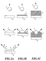
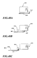
- Figs. 1A to 1C are diagrammatic illustrations for explaining behavior in rebounding or so forth caused when colliding of a liquid droplet with a liquid layer formed on the printing medium.
- Fig. 1A shows the case where the liquid droplet directly collides with the printing medium
- Fig. 1B shows the case where the liquid droplet collides with a relatively thin liquid layer on the printing medium
- Fig. 1C shows the case where the liquid droplet collides with a relatively thick liquid layer.
- respective of Figs. 1A to 1C show variation of behavior associating with elapsing of time from upper side to down in order.
- a speed of the liquid droplet is the same to each other.
- the direction of the rebounding liquid droplet (not shown) is the same as the former examples.
- most of the liquid forming the liquid droplets which forms the rebounding mist is the liquid of the liquid layer 3. This is because that, upon occurrence of collision of the liquid droplet 1 with the liquid layer 3, due to thickness of the liquid layer 3, an energy of collision is transferred to the liquid forming the liquid layer 3 rather than reactively acting on the liquid droplet 1. It should be noted that when the speed of the liquid droplet 1 is increased, the behavior upon collision becomes closer to the condition shown in Fig. 1B.
- the rebounding mist in cone shape has low possibility of deposit on the ejection opening per se which ejected the liquid droplet, such as the ink droplet or the processing liquid droplet. Even if deposited, the deposition amount is quite small. However, in the case of an ink-jet head arranged a plurality of ejection openings, it is possible that the rebounding mist caused by the ink or so forth ejected from adjacent ejection opening may be deposited on the ejection opening or in the vicinity thereof.
- the covering range is set to open only at the portion corresponding to the ejection opening and the circumference in the vicinity thereof. By this, the amount of deposition of the rebounding mist particularly on the adjacent ejection opening and in the vicinity thereof, can be reduced.
- the inventors have found that depositing condition of the liquid including the depositing region is significantly differentiated depending upon a distance between the ink-jet head and the printing medium (hereinafter referred to as "a paper distance").
- a paper distance a distance between the ink-jet head and the printing medium.
- the covering range is set appropriately in this viewpoint.
- Figs. 2A to 2D are diagrammatic illustration showing difference of rebounding mist and depositing condition depending upon the paper distance. Respective conditions shown in these figures are illustrated under a condition where the ejection amount of each ejection openings is 7 to 15 [p1] at ejection speed of 10 to 20 [m/sec]. In addition, respective ejection duties are mutually the same.
- Figs. 2A to 2D are illustrated under the condition where a phase of rebounding mist is symmetric with respect to the ejection openings of the ink-jet head.
- the ink-jet head moves relative to the printing medium. Therefore, symmetry of the phase in precise sense can not be guaranteed.
- a following discussion is in touch with the deposition of the rebounding mist and essentially not in touch with symmetry.
- offset from symmetric position due to component in the relative motion direction of the speed of the liquid droplet, is quite small. Accordingly, the following discussion is essentially reasonable even for the case where the ink-jet head moves relative to the printing medium.
- Fig. 2A is an illustration showing behavior of the rebounding mist at the paper distance of 2.0 mm and a condition of deposition of the mist on the ejection opening forming surface.
- ink droplets ejected from an ejection opening 6 of an ink-jet head 5 rebound on the printing medium 2 to form rebounding mist 7.
- Most of the droplets of rebounding mist 7 do not reach an ejection opening forming surface 5A for relatively large paper distance. Accordingly, little mist may be deposited on the ejection opening forming surface 5A.
- a little mist 7 start to be deposited on a portion around but distanced from the ejection openings.
- the mist may deposited on a region relatively close to the ejection openings 6.
- little mist is deposited on the ejection opening or in the vicinity thereof.
- mist may be deposited at both sides of array of the ejection openings substantially along alignment direction of the ejection openings.
- the condition of the rebounding mist becomes different from those discussed with respect to Figs. 2A and 2B. More specifically, paying attention to one ejection opening, when the ejection duty is relatively low and thus ejection is effected intermittently, for example, the rebounding mist to be formed with respect to the ejection opening in question becomes substantially the same as those discussed with reference to Figs. 2A and 2B. However, the ejection duty is increased beyond a some value, ejection becomes continuous to generate a swirl of the rebounding mist. For such swirl formation, the ejection duty is one of important factor, but the paper distance and the ejection period are also important factors.
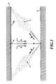
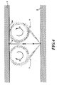
- Figs. 3 and 4 are diagrammatic illustrations for explaining the process of formation of the swirl by the rebounding mist. It should be noted that the following discussion including discussion for formation of the swirl has been given on a basis of prediction from condition of mist deposition on the ejection opening forming surface.
- the range to be covered with the member for covering the ejection opening forming surface is determined depending upon the paper distance set in an apparatus construction. For example, in the case of the apparatus in which the paper distance is relative large as shown in Fig. 2A and thus there is no the possibility of deposition of the rebounding mist, no problem will be arisen even when the covering member is not provided. Further, in the case of the apparatus, in which the range of deposition of the mist is the distanced circumferential portion as shown in Fig. 2B, it should be effective to cover at least the circumferential portion.
- substantially overall portion has to be covered with providing opening only at the portion corresponding to the ejection opening and the portion in the vicinity of the ejection opening.
- a construction for wiping the ejection opening forming surface should be differentiated.
- deposition of the insoluble matter on the ejection opening forming surface can be appropriately prevented.
- water droplet caused by dew condensation due to temperature variation of the ink-jet head or paper dust can be removed effectively.
- a covering manner of the cover means for the ink-jet head is differentiated depending upon ejection order of the ink and the processing liquid for making the ink insoluble or an ink containing the processing liquid.
- discussion will be given for conditions of deposition of the insoluble matter on respective ink-jet head depending upon the ejection order.
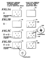
- Figs. 5A to 5D are diagrammatic illustrations for explaining difference of the liquid droplet to be deposited on respective ejection opening forming surface depending upon the order of ejection when an ink-jet head for ejecting a processing liquid S (hereinafter referred to as “processing liquid head”) and an ink-jet head for ejecting a black ink K (hereinafter referred to as “black ink head”) are employed.
- processing liquid head processing liquid S
- black ink head black ink head
- a liquid droplet of the processing liquid S containing one or two coagulated substance may be occasionally deposited on the ejection opening forming surface 5A of the processing liquid head, and a deposition amount is smaller than that of the black ink head shown in Fig. 5C.
- the liquid droplet of only black ink is deposited on the ejection opening forming surface 5A of the black ink head.
- Figs. 6A and 6B are illustration showing difference of liquid deposition depending upon difference of the order of ejection shown in Figs. 5C and 5D.
- Fig. 6A corresponds to Fig. 5C and shows generation of the rebounding mist when ejection is performed in the order of the processing liquid S and then the black ink K.
- Fig. 6B corresponds to Fig. 5D and shows generation of the rebounding mist when ejection is performed in the order of the black ink K and then the processing liquid S.
- the rebounding mist is generated in a manner that the liquid droplet collides with the printing medium so that a part of the colliding liquid droplet is separated to fly, as the rebounding mist. More specifically, when the processing liquid or the black ink has already been ejected depending upon order of ejection, the already ejected processing liquid or the black ink forms a thin layer of liquid on the printing medium. Then, subsequently hitting of the black ink or the processing liquid causes own deformation and separation to cause flying of fine droplets rather than splashing to generate the fine flying droplet of the liquid in the thin layer with crowding out the liquid surface of the thin layer. Accordingly, most part of the liquid droplet forming the rebounding mist is the later ejected liquid and partly contain the preliminarily ejected liquid at the boundary of two liquids contacting with the later ejected liquid upon collision.
- the processing liquid S has already been ejected and forms the thin layer
- collision of the black ink with the processing liquid cause flying fine droplet primarily containing the black ink and partly containing the black ink K.
- reaction having directionality directed from the processing liquid S side to the black ink K side is caused to generate the coagulated substance to contain relatively large amount of coagulated substance in the black ink which forms the rebounding mist.
- a deposition amount of the insoluble substance is different depending upon the order of ejection. Therefore, in the third example of the shown embodiment, in a plurality of ink-jet head ejecting the processing liquid S and other inks, arrangement of the covering means is differentiated depending upon order of ejection.
- the cover means is provided for preventing deposition of the insoluble substance at least on the ejection opening and in the vicinity thereof while deposition of the insoluble substance on the ejection opening forming surface is permitted.
- Fig. 7 shows one example of the fourth example of the covering means, which cover the circumferential portion distanced from the ejection opening array of the ejection opening forming surface 5A of the ink-jet head in certain extent in the case that, the paper distance is set at the distance shown in Fig. 2C.
- the fourth example has been worked out with paying attention for the fact that, when the cover shown in Fig. 7 is employed in the case of the foregoing paper distance, while the rebounding mist may be deposited on the ejection opening portion and in the vicinity thereof, a deposition distribution shown in Fig. 7 is caused by an effect of an air flow generated by scanning of the ink-jet head as discussed later in connection with a second embodiment.
- the covering member set forth above is intended to finally prevent or reduce deposition of the insoluble substance
- the covering member can of course achieve the similar function and effect in preventing of deposition of the ink on the ejection opening forming surface even in the ink-jet apparatus employing only normal ink.
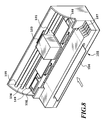
- Fig. 8 is a perspective view showing general construction of one embodiment of an ink-jet printing apparatus according to the present invention.
- a printing paper 106 inserted into a paper feeding position of an apparatus is fed to a region where printing can be effected by an ink-jet head unit 103 (hereinafter referred to as "printing region"), by a feeder roller 109.
- print region a region where printing can be effected by an ink-jet head unit 103 (hereinafter referred to as "printing region"), by a feeder roller 109.
- a platen 108 is provided on the back surface portion of the printing medium.
- a carriage 101 is constructed for movement in a predetermined direction by two guide bars 104 and 105.
- the ink-jet head unit 103 can reciprocally scan the printing region.
- the carriage 101 can mount respective of the following units. Namely, on the carriage 101, the ink-jet head unit 103 including ink-jet heads for ejecting a plurality of colors of inks and the processing liquid, ink tanks for supplying the ink or the processing liquid for respective of the ink-jet heads, is mounted.
- black (Bk), cyan (C), magenta (M) and yellow (Y) inks may be employed as a plurality of colors of inks.
- a recovery system unit 110 is provided at the lower portion.
- the ejection opening portion of the ink-jet head can be capped by the recovery system unit 110.
- the left end position is referred to as home position of respective ink-jet heads.
- the reference numeral 107 denotes a switch portion and a display element portion.
- the switch portion is used for turning ON and OFF of a power source of the ink-jet printing apparatus, setting of various printing modes and so forth.
- the display portion is used for displaying various states of the printing apparatus.
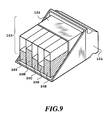
- Fig. 9 is a perspective view showing one example of the ink-jet head unit 103 which can be mounted on the carriage 101.
- ink-jet heads respectively ejecting Bk, C, M and Y inks and the processing liquid are mounted as a head unit 102.
- Bk ink tank 20K, C ink tank 20C, M ink tank 20M, T ink tank 20Y and processing liquid tank 21 are also mounted on the carriage 101.
- Respective tanks are connected to corresponding ink-jet heads through connecting portions for supplying the ink or the processing liquid.
- the construction of the ink-jet head unit is not specified to the shown construction but can be constructed in various fashion.
- the processing liquid tank and the Bk ink tank may be integrated with each other, and also the C ink tank, M ink tank and Y ink tank may be formed as integrated construction.
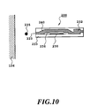
- Fig. 10 is an enlarged section showing a detailed construction of the ink-jet head for ejecting each color of ink or the processing liquid.
- an ink-jet head 200 employs a system, in which a plurality of ejection openings are provided, and a plurality of heating bodies of electrothermal transducers are arranged corresponding to respective ejection openings for ejecting the ink or the processing liquid by applying driving signals corresponding to ejection information to respective of the heater elements.
- the heater elements 230 are constructed to head independently per the ejection opening.
- the ink or the processing liquid in an ink passage 240 abruptly heated by heating of the heater element 230, generates bubble by film boiling for ejecting the ink or the processing liquid 235 toward the printing paper 106 by the pressure of generation of bubble.
- character, graphic image or so forth is printed on the printing medium 106.
- volume of any ejected liquid drop of colors of inks and the processing liquid are normally 5 to 80 ng.
- ink passage 240 communicated thereto is provided.
- a common liquid chamber 232 for supplying the ink or the processing liquid for respective of the ink passages 240.
- the foregoing heat elements 230 set forth above and electrode wiring (not shown) for supplying an electric power to the former are provided.
- These heater elements 230 and the electrode wiring are formed on a substrate 233 of silicon or so forth by layer forming technology.
- a protection layer 236 is formed for preventing the ink from directly contacting with the heater body.
- a partitioning wall 234 of resin or glass material is laminated to form the ejection opening, the ink passage and the common liquid chamber.
- the printing system employing the heater body utilizes bubble formed by charging of thermal energy upon ejection of the ink droplet, it is called as bubble-jet system.
- the processing liquid or solution for making ink dyestuff insoluble can be obtained in the following manner.
- the resultant mixture is pressure-filtered with the use of a membrane filter of 0.22 ⁇ m in pore size (tradename : Fuloroporefilter, manufactured by Sumitomo Electric Industries, Ltd.) so that yellow ink Y1, magenta ink M1, cyan ink C1 and black ink K1 can be obtained.
- a membrane filter of 0.22 ⁇ m in pore size (tradename : Fuloroporefilter, manufactured by Sumitomo Electric Industries, Ltd.) so that yellow ink Y1, magenta ink M1, cyan ink C1 and black ink K1 can be obtained.
- the aforementioned processing liquid and ink are mixed with each other at the position on the printing medium or at the position where they enter in the printing medium.
- the ingredient having a low molecular weight or cationic oligomer among the cationic material contained in the processing liquid and the water soluble dye used in the ink having anionic radical are associated with each other by an ionic mutual function as a first stage of reaction whereby they are instantaneously separated from the solution liquid phase.
- the aggregated material formed by the ingredient having a low molecular weight or the cationic oligomer of the cationic material and the anionic dye by way of the aforementioned mechanism has increased viscosity.
- the aggregated material does not move as the liquid medium moves, ink dots adjacent to each other are formed by inks each having a different color at the time of forming a full colored image but they are not mixed with each other. Consequently, a malfunction such as bleeding does not occur.
- the aggregated material is substantially water-insoluble, water resistibility of a formed image is complete. In addition, light resistibility of the formed image can be improved by the shielding effect of polymer.
- insoluble or “aggregation” refers to observable events in only the above first stage or in both the first and second stages.
- plain paper such as copying paper, bond paper or the like conventionally used
- coated paper specially prepared for ink jet printing and OHP transparent film are preferably used.
- ordinary high quality paper and bright coated paper can preferably be used.
- Fig. 11 is a perspective view showing one example of the recovery unit 110 in the shown embodiment of the printing apparatus.
- a Bk ink head cap 112 a C ink head cap 114, a M ink head cap 115, a Y ink head cap 116 and a processing liquid head cap 113 are provided. Respective caps are provided movably in vertical direction. By this, when the head unit is located at the home position, respective caps are fitted onto the ejection opening forming surface of respective of corresponding ink-jet heads for capping to prevent evaporation of the ink or the processing liquid in the ejection openings of the ink-jet heads and whereby to prevent ejection failure due to increasing of viscosity plugging of the ink caused by evaporation.
- Respective caps in the recovery unit is connected to not shown pump units so that vacuum pressure may be generated within the caps upon suction recovery process for sucking the ink in the condition where the cap units and the ink-jet heads are mated with each other.
- the pump units are provided as a pump unit dedicated for the processing liquid, and as respectively independent pump units for respective of heads for ejecting inks. Waste liquid resulting from suction recovery is fed to a waste tank through respectively independent waste liquid passages. This is for preventing respective colors of inks from contacting with the processing liquid in the cap or in the pump to be insoluble in the pump.
- the pump units may also be two, wherein one is for the processing liquid and the other is for respective colors of inks.
- a processing liquid wiping blade 117 for performing wiping of the ejection opening forming surface of the processing liquid ejecting ink-jet head, and a printing ink wiping blade 118 for wiping the ejection opening forming surface of the printing ink ejecting ink-jet heads are provided.
- These blades are formed of elastic member, such as rubber or so forth for wiping the ink or the processing liquid depositing on the ejection opening forming surfaces of respective ink-jet heads.
- respective wiping blades are movable between an extracted or lifted-up position for wiring the ejection opening forming surfaces by motion of respective ink-jet heads and a retracted or lowered position so as not to interfere with the ejection opening forming surfaces by means of a not shown lifting device. It should be noted that detailed operation will be discussed later.
- the processing liquid wiping blade 117 for wiping the processing liquid ejecting portion and the printing ink wiping blade 118 for wiping the ink ejecting portion are provided independently. Also, the processing liquid wiping blade 117 and the printing ink wiping blade 118 are constructed to independently move in vertical direction.
- Fig. 12 is a block diagram showing a construction of a control system of the shown embodiment of the ink-jet printing apparatus.
- image data data of character and image for printing (hereinafter referred to as "image data") from a host computer is input to a reception buffer 401 of the shown embodiment of the printing apparatus.
- image data data confirming whether the data is accurately transferred or not, or data for notifying operating condition at the printing apparatus side is transferred from the printing apparatus to the host computer.
- the image data stored in the reception buffer 401 is transferred to a memory portion 403 under management of a CPU 402 and is temporarily stored in a RAM (random-access memory).
- a mechanical component control portion 404 is responsive to a command from the CPU 402 for driving mechanical components 405, such as a carriage motor, a line feeding motor and so forth.
- a sensor/SW control portion 406 transfers signal from a sensor/SW portion 407 comprising various sensors and SW (switches).
- a display element control portion 408 controls a display element portion 409 comprising LED of display panel group, a liquid display element and so forth in response to a command from the CPU 402.
- a head control portion 410 is responsive to a command from the CPU 402 for controlling driving of respective ink-jet heads 200. On the other hand, concerning states of ink-jet heads 200, the head control portion 410 provides temperature information or so forth detected by not shown sensor to the CPU 402.
- Fig. 13 is an illustration showing one example of a head unit at the ejection opening forming surface, which can construct the ink-jet head unit 103 shown in Fig. 8.
- the head unit 102 is constructed with two ink-jet heads 200Bk1 and 200Bk2 both ejecting the black ink and a ink-jet head 200S ejecting the processing liquid S.
- Respective of the head chips 200Bk1, 200S and 200Bk2 have a construction similar to that shown in Fig. 10. The ejection characteristics is as shown below.
- the ink-jet heads 200Bk1 and 200Bk2 for ejecting black ink K are arranged at both sides of the ink-jet head 200S ejecting the processing liquid S.
- the head unit 102 printing of black image in both of scanning directions A and B of the carriage 101.
- ejection is performed in the order of the ink-jet head 200Bk1 and then the ink-jet head 200S during printing in the scanning direction A, and in the order of the ink jet head 200Bk2 and then the ink-jet head 200S during printing in the scanning direction B. Therefore, it is preferred that ejection of black ink K is always performed in advance of ejection of the processing liquid S. By this, concerning the rebounding mist depositing on the ink-jet head 200S, little insoluble substance is admixed. Then, in this case, if the cover member set out later is provided on the head though only little insoluble substance is admixed, the cover member can be set on the ejection opening forming surface of the ink-jet head 200S.
- the cover member in the case that the order of ejection is set to first eject the processing liquid S and then the black ink K, the cover member can be provided the ejection opening forming surfaces of the black ink ejecting heads 200Bk1 and 200Bk2. By this, it can be possible to prevent the rebounding mist containing relatively large amount of coagulates from deposition on the ejection openings and in the vicinity thereof.
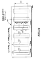
- Fig. 14 is a diagrammatic illustration showing another example of the head unit at the ejection opening forming surface, which forms the ink-jet head unit 103 shown in Fig. 8.
- the head unit in the shown embodiment is constructed with an ink jet head 200Bk for ejecting the black ink, an ink-jet head 200S ejecting the processing liquid, and an ink-jet head 200CMY, in which respective ejection portions ejecting the C, M and Y inks.
- Respective head chips of the ink-jet heads are arranged at a pitch of 1/2 inches or 1 heads 200Bk, 200S and 200CMY are arranged at distances of 1/2 inch and 1 inch, respectively by means of on frame 204.
- the reason why 1 inch of pitch is provided between the head 200S and the head 200CMY is for enabling to use an ink tank employed in the construction shown in Fig. 13 for black ink and the processing liquid.
- the ink-jet head 200Bk for ejecting the black ink K is similar to that illustrated in Fig. 13. Ejection characteristics of the ink-jet heads 200S and 200CMY of the processing liquid S and respective color inks C, M and Y, respectively are as follows:
- the head unit shown Fig. 14 is also employed for bidirectional printing.
- ejection is performed in the order of black ink K and then the processing liquid S in printing in the direction A, and ejection is performed in the order of cyan C, magenta M and yellow Y and then the processing liquid S in printing in the direction B.
- ejection is performed in the order of black ink K and then the processing liquid S in printing in the direction A
- ejection is performed in the order of cyan C, magenta M and yellow Y and then the processing liquid S in printing in the direction B.
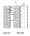
- Figs. 15A and 15B are diagrammatic illustrations for explaining the first example of a cover plate as the covering means which can be provided for respective ink-jet heads set out with respect to the shown embodiment
- Figs. 16A to 16E are illustrations for explaining wiping operation for the ejection opening forming surfaces of respective ink-jet heads when the cover plates are set.
- the cover plate 208 has an ejection hole 208A corresponding to respective ejection openings.
- the ejection opening forming surface 205A can be covered except for the ejection holes 208A.
- a diameter of the ejection hole 208A may be determined depending upon the paper distance as set forth above. Assuming that the paper distance in the shown embodiment of the apparatus is 1 mm for example, the swirl is generated by the rebounding mist to make it possible for the mist to be deposited on the positions quite close to the ejection opening. Therefore, the diameter of the ejection hole 208A is set to be 50 ⁇ m so that deposition of the mist may not occur even when the swirl of the rebounding mist is generated.
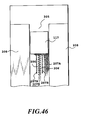
- Installation of the cover plate 208 onto the ink-jet head can be done by providing a spacer 201 on the ejection opening forming surface 205A as shown in Fig. 17 and by slidably providing the cover plate 208 with respect to the ink-jet head 200.
- fixing of the cover plate 208 to the ink-jet head can be done by forming the cover plate of a material which can be drawn by a magnetic force, and by forming a part of the spacer 201 of the ink-jet head as a part of the electromagnet. Upon wiping by the blade and capping, drawing force by the electromagnet is released to permit sliding of the cover plate 208 as shown in Fig. 15B.
- Figs. 16A to 16E show wiping operation associating with sliding stated above.
- Fig. 16A shows a condition where scanning is performed for printing with providing the cover plate 208 on each ejection opening forming surface of the ink-jet head unit 103 by holding force of the electromagnet.
- the ink-jet head unit 103 is moved to the home position and the cover plate 208 is opposed to a plate holder 209 located adjacent the recovery unit 116 (see Fig. 8). Then, by forming the plate holder 209 with the electromagnet, the cover plate 208 can be held by switching the electromagnet (Fig. 16B). At this time, the plate holder 209 is moved to high position than a stand-by position, and is lowered to the stand-by position after holding the cover plate 208 by a not shown sliding mechanism. Simultaneously with lowering, the ink-jet unit reverses moving direction after reaching to an end position of the apparatus (Fig. 16D). Associating with reversal motion, the blade 118 or 117 (see Fig. 11) is lifted up depending upon the timing of the corresponding ink-jet head for wiping respective ejection opening forming surface (Fig. 16E).
- Figs. 18A to 18C are plan views showing modifications of the first example of the cover plate, and Fig. 18D is a section of the ink-jet head covered by these cover plates.
- the ink-jet heads shown in these drawings respectively have two ejection opening arrays for each color of ink or for the processing liquid, and by offsetting arrangement positions of the ejection openings in respective arrays, the ejection opening array achieving twice higher resolution with respect to each color ink or the processing liquid can be provided.
- the ejecting system is adapted to eject ink droplet in a direction perpendicular to a plane of the heater 212 constructed with the electrothermal transducer.
- relatively fine ink droplet can be ejected by appropriately setting the distance between the heater 212 and the ejection opening 206.
- the ejection holes 208A are formed for respective of individual ejection openings similarly to the cover plate of Fig. 15.
- the ejection holes 208A are formed per every two ejection openings.
- an opening portion is provided corresponding to the entire ejection opening array. The configurations or the sizes of the opening in these examples are also determined in consideration of the deposition region of the rebounding mist determined depending upon the paper distance as second example of the shown embodiment.
- the cover plate 208 is slidably provided with respect to the ink-jet head to enable ejection recovery operation, such as wiping or so forth directly to the ejection opening forming surface of the ink-jet head.
- the cover plate is not necessarily slidable with respect to the ejection opening forming surface, and can be fixed thereon. In this case, capping is performed with respect to the cover plate.
- water droplet or so forth other than the rebounding mist depositing on the ejection opening forming surface cannot be removed by wiping.
- driving of the electrothermal transducer is appropriately controlled to generate bubble which does not cause ejection to project meniscus of the ink or so forth for admixing the water droplet located in the vicinity of the ejection opening to remove the water droplet through the preliminary ejection operation.
- cover plate may be fixedly set on the ink-jet head, or can be detachable with respect to the head.
- Fig. 19 is a diagrammatic illustration showing a second example of the head unit and the cover plate thereof.
- the cover plate of the shown example is adapted to the head unit in different form than the head unit shown in Fig. 13.
- the cover plate is slidably provided to the head unit.
- Figs. 21A to 21E are illustrations for explaining wiping operation in the shown example.
- the head unit of the shown example is provided two ejection opening arrays for each ink-jet head.
- the arrays are offset for half of a pitch of the ejection openings.
- the cover plates 208 are formed integrally for covering the ejection opening forming surfaces of two ink-jet heads except for opening portions 208B.
- the range to be covered is determined according to the second example of the shown embodiment set forth above.
- the amount of the insoluble substance contained in the mist tp be deposited on the ejection opening forming surface is not so large as set forth above. Therefore, no serious problem will be arisen even when this surface is not covered with the cover plate.
- the wiping operation with respect to the construction set forth above (and releasing operation of the cover plate for capping) is differentiated from the case of the foregoing first example.
- Directions of sliding of the cover plate and of wiping become aligning direction of the ejection openings of respective ink-jet head. More specifically, as shown in Fig. 21A, when the ink-jet unit 103 is moved at the position for opposing to the recovery unit 116 (see Fig. 8), at the condition where the ink-jet unit 103 stops, the cover plate 208 slides in the primary scanning direction and in the vertical direction (Fig. 21B). It should be noted that the sliding is enabled by not shown plate holding and sliding mechanism.
- the blades 118 and 117 mounted on this plate perform wiping of the ejection opening forming surface of the ink-jet head respectively corresponding thereto.
- the surface of the cover plate 208 is also wiped by a blade 210 (Fig. 21B).
- a solvent for dissolving the insoluble substance is impregnated in the blade 210.
- the cover plate 208 Furthermore, by sliding of the cover plate 208, the blades 118 and 117 mounted on the cover plate 208 are in contact with a wiper cleaner 211 so that water droplets and so forth depositing on the blades 118 and 117 may be removed by relative sliding movement (Fig. 21C). Subsequently, the cover plate slides in opposite direction to the former sliding direction, in which wiping operation by means of the blades 118, 117 and 210 similar to the foregoing is performed (Figs. 21D and 21E).
- cover plate of the foregoing example it should not be limited to the shown slidable cover plate but can be fixed cover plate or so forth.
- Fig. 20 is a perspective view showing modification of the cover plate 208.
- the head unit 102 of the shown modification is the same as that of Fig. 19, and only cover plate is differentiated.
- the cover plate 208 shown in Fig. 20 is adapted to cover the ejection opening forming surface 205 except for the portion around two ejection opening arrays even for the ink-jet head 200S.
- ink passages are provided in communication with the ejection opening.
- the electrothermal transducer for generating thermal energy is formed in each of the ink passages.
- a contact pad 210A provided on a wiring substrate 210 is used for establishing electrical contact between the ink-jet head and the apparatus main body.
- the cover plate 208 is formed by bonding a stainless (SUS) plate on the ejection opening forming surface by a bonding material.
- the ink-jet heads of respective colors are fixed by support members 209. Then, similarly to the above, ejection is performed in the order of heads 200BK2, 200S and then 200BK1, namely in the order of the black ink, the processing and then the black ink for printing one pixel.
- a thickness of the cover plate 208 is 0.3 mm, and a length of the opening portion of the cover plate 208 in x direction in the drawing is 2.5 mm and in y direction is 18 mm.
- Three opening portions illustrated are the same dimension.
- the entire cover plate has sizes of 40 mm in the x direction, and 20 mm in the y-direction in the drawing.
- a plate width between respective heads in the x direction is 10.2 mm.
- an edge of the opening portion is desirably substantially perpendicular to the general surface of the cover plate.
- Each ink-jet head is designed for ejecting 8.5 pl in volume ejected liquid droplet at 18 m/s of ejection speed.
- ejection openings are arranged for achieving resolution of 300 dpi in one array.
- a distance from the ejection openings to the printing paper 106, that is, the paper distance is 1.3 mm.
- the driving frequency of respective head is 10 kHz, and the printing resolution is 600 dpi.
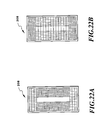
- Figs. 22A to 22B are diagrammatic illustrations showing a third example of the cover plate.
- the cover plate is constructed by forming a mesh of fiber of the predetermined material.
- the rebounding mist can be certainly captured.
- the example shown in Fig. 22B is designed to provide a distribution of the mesh density so that smaller density of the mesh for the portion corresponding to the ejection opening array than that of other portion so as not to interfere ejection of the ink or so forth and to capture the rebounding mist having greater diameter than possible diameter of the rebounding mist depositing in the vicinity of the ejection openings.
- the fourth example of the shown embodiment employs the cover plate as the covering means set forth above for controlling range of deposition of the rebounding mist.
- Ink usable for carrying out the present invention should not be limited only to dyestuff ink, and pigment ink having pigment dispersed therein can also be used. Any type of processing liquid can be used, provided that pigment is aggregated with it. The following pigment ink can be noted as an example of pigment ink adapted to cause aggregation by mixing with the processing liquid A1 previously discussed. As mentioned below, yellow ink Y2, magenta ink M2, cyan ink C2 and black ink K2 each containing pigment and anionic compound can be obtained.
- the following materials are poured in a batch type vertical sand mill (manufactured by Aimex Co.), glass beads each having a diameter of 1 mm is filled as media using anion based high molecular weight material P-1 (aqueous solution containing a solid ingredient of styrene methacrylic acid ethylacrylate of 20 % having an acid value of 400 and average molecular weight of 6000, neutralizing agent : potassium hydroxide) as dispersing agent to conduct dispersion treatment for three hours while water-cooling the sand mill. After completion of dispersion, the resultant mixture has a viscosity of 9 cps and pH of 10.0.
- the dispersing liquid is poured in a centrifugal separator to remove coarse particles, and a carbon black dispersing element having a weight-average grain size of 10 mm is produced.
- the final product has a solid ingredient of about 10 %.
- Anionic high molecular P-2 (aqueous solution containing a solid ingredient of 20 % of stylen-acrlylic acid methyl methaacrylate having an acid value of 280 and an average molecular weight of 11,000, neutralizing agent : diethanolamine) is used as a dispersing agent and dispersive treatment is conducted in the same manner as production of the black ink K2 whereby yellow color dispersing element having a weight-average grain size of 103 nm is produced.
- the thus obtained yellow dispersing element is sufficiently dispersed in water to obtain yellow ink Y2 for ink jet printing and having pigment contained therein.
- the final product of ink contains a solid ingredient of about 10 %.
- Cyan colored-dispersant element having a weight-average grain size of 120 nm is produced using anionic high molecular P-1 as dispersing agent, and moreover, using the following materials by conducting dispersing treatment in the same manner as the carbon black dispersing element.
- composition of cyan colored-dispersing element composition of cyan colored-dispersing element
- the thus obtained cyan colored dispersing element is sufficiently stirred to obtain cyan ink C2 for ink jet printing and having pigment contained therein.
- the final product of ink has a solid ingredient of about 9.6 %.
- Magenta color dispersing element having a weight-average grain size of 115 nm is produced by using the anionic high molecular P-1 used when producing the black ink K2 as dispersing agent, and moreover, using the following materials in the same manner as that in the case of the carbon black dispersing agent.
- composition of the magenta colored dispersing element composition of the magenta colored dispersing element
- Magenta ink M2 for ink jet printing and having pigment contained therein is obtained by sufficiently dispersing the magenta colored dispersing element in water.
- the final product of ink has a solid ingredient of about 9.2 %.
- the mist is generated by rebounding on the printing medium when the ink and the processing liquid are ejected in overlaying manner, at least deposition of the mist on the ejection opening forming surface of the ink ejecting portion can be prevented by the covering means.
- the second embodiment of the present invention has been worked out in different viewpoint with respect to the cover plate shown in the first embodiment. More specifically, the second embodiment of the present invention has been made in consideration of behavior of air flow generated around the cover plate when the cover plate is provided.
- the shown embodiment is designed for controlling a deposition range of the mist of the ink or so forth by means of the air flow.
- the ink droplet or the processing liquid droplet hitted on the printing medium generates substantially cone shaped rebounding mist in a given angle.
- the mist flows back to the ink-jet head at substantially the given angle.
- the processing liquid and the ink are ejected from the ink-jet heads (from respectively different ink-jet heads) with a certain time difference, to the ink droplet or the processing liquid ejected in former ejection and already hitted on the printing medium, the later ejected processing droplet or the ink droplet is hitted. Then, in such case, substantially the cone shape rebounding mist is generated. In this case, the mist is generated by collision of the ink with the processing liquid having mutually different properties, and then mixture of the processing liquid and the ink may be contained in the mist.
- the content of the rebounding mist can be significantly differentiated depending upon order of ejection of the processing liquid and the ink.
- the processing liquid is ejected in advance of ejection of the ink, relatively large amount of coagulate or insoluble substance resulting from reaction of the processing liquid with the ink is contained in the mist.
- the ink is ejected first and subsequently the processing liquid hits on the ink droplet on the printing medium, little coagulate is contained in the mist.
- One example of the shown embodiment is designed for controlling deposition range of the mist in consideration of order of ejection of the ink and the processing liquid.
- the form of the rebounding mist may be varied primarily depending upon distance between the ink-jet head and the printing medium.
- mist Even if any form of the rebounding mist is generated, there is a possibility that the mist is deposited on the ejection opening portion or in the vicinity thereof on the ejection opening forming surface of the ink-jet head. Particularly, when the mist containing large amount of insoluble substance is deposited on the ejection opening portion or in the vicinity thereof, serious ejection failure can be caused as set forth above.
- Figs. 23 and 24 are illustrations for explaining such control of the deposition range.
- the cover plate in order to prevent deposition of the mist onto the ejection opening forming surface of the ink-jet head, the cover plate is positively used for controlling the deposition range.
- the condition of the rebounding mist depending upon the paper distance is to flow in cone shape (Fig. 23) or to form the swirl (Fig. 24).
- air flow relative to the ink-jet head is generated by scanning motion of the ink-jet head 5.
- This air flow causes turning flow E by presence of the cover plate 8 located at upstream side of the air flow. More specifically, the air flow flowing along the surface of the cover plate 8 causes separation of the flow at the corner 9j of the upstream side cover plate 8 to cause the flow E turning into the backside of the cover plate 8.
- the rebounding mist is guided to flow into the backside of the cover plate distanced away from the ejection opening 6.
- the cover plate 8 by appropriately arranging the cover plate 8, the deposited position of the rebounding mist can be controlled.
- projecting portions provided at the boundary of the ejection opening forming surfaces or respective colors of ink ejecting portions may be utilized in place of the cover plate as set forth above. More specifically, by appropriately determining the configuration or so forth of such projection portions, deposition range of the rebounding mist can be controlled to the desired range.
- desired configuration of the general projecting portion including the cover plate set forth above is to cause a flow turning into the back side of the projecting portion as the projecting portion located upstream side of the air flow.
- a configuration which initially cause flow along the profile of the projecting portion and then cause separation therefrom may be considered.
- a configuration which may not disturb a flow caused at a position distanced therefrom is desired.
- control of the mist deposition range is positively utilized.
- the mist formed as set forth above is in floating condition between the ink-jet head and the printing medium.
- a motion energy applied for the mist upon ejection from the head particularly for the energy applied when a droplet in amount less than or equal to 25 pl is ejected in kinetic momentum less than or equal to 400 p1.m/sec is consumed by air resistance or so forth after rebounding on the printing medium, and finally becomes quite small in cone shape or swirl form.
- the mist becomes floating condition.
- the mist in the floating condition can be easily moved utilizing the air flow, for example. In the shown example, utilizing this fact, position of deposition is varied depending upon primary component contained in the mist.
- the ink and the processing liquid for making the ink insoluble are employed, or in the case that the same color or different colors of inks mutually reacting to be insoluble are employed, it is not desirable to deposit the insoluble substance on the ejection opening or in the vicinity thereof. Therefore, by appropriately determining the air flow and/or the position of the projecting portion, such as the cover plate or so forth, deposited position of the mist can be set away from the ejection opening.
- the mist deposited on the ejection opening forming surface may be removed by wiping.
- the second embodiment of the present invention will be discussed hereinafter more concretely.
- the ink-jet printing apparatus, the processing liquid and so forth to be employed in the shown embodiment are similar to those employed in the first embodiment. Therefore, discussion for those will be neglected for avoiding redundant discussion and for maintaining the disclosure simple enough to facilitate clear understanding of the invention.
- Fig. 25 is an illustration showing a condition where the head unit 102 is performing printing operation. It should be noted that in these drawings, the head units 102 for Y, M and C inks are neglected from illustration.
- ejection openings 206 are arranged in two arrays. Arrangements of ejection openings in respective arrays are offset for 1/2 of pitch of the ejection openings relative to each other. By this, it becomes possible to perform printing at twice higher resolution of the resolution to be realized by one ejection opening array.
- the cover plate 208 covers the ejection opening forming surface 205 except for the portion around two ejection opening arrays.
- ink passages are provided in communication therewith.
- the electrothermal transducer for generating thermal energy is formed in each of the ink passages.
- a contact pad 210A provided on a wiring substrate 210 is used for establishing electrical contact between the ink-jet head and the apparatus main body.
- the cover plate 208 is formed by bonding a stainless (SUS) plate on the ejection opening forming surface by a bond.
- the ink-jet heads of respective colors are fixed by support members 209. Then, similarly to the above, ejection is performed in the order of heads 200BK2, 200S and then 200BK1, namely in the order of the black ink, the treatment and then the black ink for printing one pixel.
- the thickness of the cover plate 208 is 0.3 mm, and the length of the opening portion of the cover plate 208 in x direction in the drawing is 2.5 mm and in y direction is 18 mm. Three opening portions illustrated are the same dimension.
- the entire cover plate has sizes of 40 mm in the x direction, and 20 mm in the y-direction in the drawing.
- a plate width between respective heads in the x direction is 10.2 mm.
- the edge of the opening portion is desirably substantially perpendicular to the general surface of the cover plate.
- Each ink-jet head is designed for ejecting 8.5 pl in volume ejected liquid droplet at 18 m/s of ejection speed.
- ejection openings are arranged for achieving resolution of 300 dpi in one array.
- a distance from the ejection openings to the printing paper 106 is 1.3 mm.
- the driving frequency of respective head is 10 kHz, and the printing resolution is 1200 dpi.
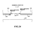
- Fig. 25 the carriage travels in the direction shown by arrow at a speed of 211.7 m/s.
- the carriage travels in the direction shown by arrow at a speed of 211.7 m/s.
- relative flow of the air is generated in the direction opposite to the traveling direction of the carriage.
- the rebounding mist from the paper surface is deposited on the ejection opening forming surface of each head as shown in Fig. 26 to reduce the mist deposition amount in the vicinity of the ejection opening.
- the ejection opening portion may directly contact with the flat surface portion to be damaged to cause ejection failure.
- the cover plate is provided, direct contract of the ejection opening portion with the flat surface portion can be successfully prevented.
- the present invention is not limited to construction, but metal, such as aluminum, resin material, such as Noryl (Trademark of General Electric), PP, polyethylene or so forth may be employed.
- cover plate and the ink-jet head integrally instead of forming separately. Also in this case, similar effect to the case where the cover plate and the ink-jet head are formed separately, can be obtained.
- the required condition is 5 pl to 25 pl of ink ejection amount, 8 m/s to 25 m/s of ejection speed, 0.5 mm to 20 mm of distance between the head and the paper, 0.1 to 1.0 mm in thickness of the plate, 1.0 to 6.0 mm in the length of x direction of the opening portion of the plate, greater than or equal to 1.0 mm in the width of the plate in x direction, higher than or equal to 50 mm/s in the carriage speed and more preferably higher than or equal to 100 mm/s.
- preferred kinetic momentum upon ejection from the head is less than or equal to 400 pl.Em/sec with respect to the droplet less than or equal to 25 pl.
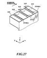
- Fig. 27 shows an example, in which only plate is differentiated in the construction shown in Figs. 25 or so forth. More specifically, as shown in Fig. 27, parts of the cover plate at both end portions in the direction of arrangement of the ejection opening in each head are removed.
- the ink droplet or so forth is deposited on the ejection opening forming surface during printing. Such deposited substance is removed by wiping.
- the shown embodiment provides good passing ability of a blade and improved wiping ability.
- the ejection openings are arranged in two ejection opening arrays, each of which has resolution of 300 dpi.
- a distance from the ejection opening to the printing paper is 1.6 mm.
- the driving frequency of each head is 10 kHz, and the printing resolution is 600 dpi.
- the mist deposition amount in the vicinity of the ejection opening can be reduced as shown in Fig. 26.
- Fig. 28 is an illustration showing a further example of the cover plate.
- the cover plate 208 is provided only around the ejection opening array of the head BK1.
- the thickness of the cover plate is 0.25 mm
- the length of the opening portion of the cover plate is 4.0 mm in x direction
- 20 mm in y direction The overall plate is 18.5 mm in x direction and 20 mm in y direction.
- the ejection volume in each ink-jet head is 4 pl, and ejection speed is 22 m/s.
- the ejection openings are arranged in two arrays at resolution of 300 dpi in each array.
- distance between the ejection opening and the paper is 1.0 mm.
- the driving frequency of each head is 15 kHz, and the printing resolution is 1200 dpi. Namely, the carriage speed becomes 317.5 mm/s.
- unidirectional printing is performed by performing ejection in the order of head BK2, then 200S and thereafter 200BK1.
- the black ink is ejected from the ink-jet head 200BK2.
- the content in the rebounding mist is only black ink. Accordingly, in this case, even when the cover plate is not provided around the ejection opening of the head 200BK2, the mist or so forth deposited can be relatively easily removed by wiping. There is no possibility to cause serious ejection failure due to the insoluble substance or so forth.
- the processing liquid is ejected from the ink-jet head 200S.
- ejection is performed in the order of black ink and then the processing liquid to generate the rebounding mist. Therefore, amount of the insoluble substance contained in the mist to be deposited is small. Furthermore, the insoluble substance is included in the processing liquid. Accordingly, even in this case, possibility of causing serious ejection failure is low.
- the ink-jet head 200BK1 when ejection of black ink is performed by the ink-jet head 200BK1, the ink is ejected on the processing liquid ejected immediately preceding timing. In this case, the rebounding mist containing large amount of insoluble substance is generated. Therefore, the cover plate 208 is provided and the mist deposition range is controlled.
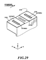
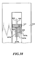
- Fig. 30 is a perspective view showing a still further example of the shown embodiment of the ink-jet head.
- the ejection openings are arranged in the width of 220 mm substantially corresponding to the length of the shorter edge of A4 size paper.
- the shown ink-jet head is so-called full line type and is used with fixing on the apparatus main body. With respect to the ink-jet head in fixed condition, the printing paper is fed relative thereto.
- the thickness of the cover plate is 0.4 mm
- the length of the opening portion of the cover plate is 6.0 mm in x direction and 240 mm in y direction.
- the size of the entire plate is 14 mm in x direction and 260 mm in y direction.
- the ejection volume in the ink-jet head is 17 pl, the ejection speed is 24 m/s.
- the ejection openings are arranged in the resolution of 600 dpi.
- the distance between the ejection opening and the paper is 1.2 mm.
- the driving frequency is 1 kHz and the printing density is 600 dpi. Namely, the feeding speed of the paper is 42.3 mm/s.
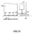
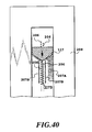
- the air flow flowing between the ink-jet head and the paper is generate by feeding of paper, and thus the velocity of the air flow is relatively small to possibly be insufficient for controlling the deposition range of the rebounding mist. Therefore, as shown in Fig. 31, a fan 220 may be provided for generating a sufficient velocity of air flow between the ink-jet head 200 and the paper 106.
- the fan 220 and a motor 221 for driving the fan are provided.
- the air flow generated by the fan 220 is guided by a guide 223 to cause 100 mm/s of air flow between the ejection opening and the paper to control deposition range of the mist, and whereby to reduce mist deposition amount in the vicinity of the ejection opening.
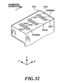
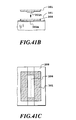
- Fig. 32 is a perspective view showing a yet further example of the shown embodiment of the head unit.
- a projecting portion 230 is provided around the region of the ejection opening array of each ink-jet head.
- the projecting portion 230 has 1.0 mm of width, 0.3 mm of height. Even in such construction, air flow shown in Figs. 23 and 24 can be caused to control range of deposition of the mist.
- the mist generated associating with liquid ejection from the head can be moved in a direction away from the ejection opening by the air flow.
- deposition of the mist on the ejection opening to cause ejection failure can be successfully prevented.
- the mist can be held in floating condition, namely in the condition easily controlled by the air flow, range of deposition of the mist can be easily controlled.
- the amount of the mist depositing on the ejection opening and in the vicinity thereof can be reduced to successfully prevent the serious ejection failure.
- a third embodiment of the present invention employs a cover plate partly covering the ejection opening forming surface for lowering the absolute amount of the insoluble substance deposited on the ejection opening forming surface of the ink-jet head (ejecting means).
- a cover plate partly covering the ejection opening forming surface for lowering the absolute amount of the insoluble substance deposited on the ejection opening forming surface of the ink-jet head (ejecting means).
- the shown embodiment is worked out in the novel viewpoint that, by the air flow generated upon scanning of the ink-jet head provided the cover plate or the step similarly to the former embodiment, deposition range of the insoluble substance can be controlled, and range of deposition is differentiated depending upon cause of mist generated by ejection of the ink and the processing liquid.
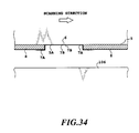
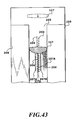
- Figs. 33 and 34 are illustrations for explaining the deposition range control by the air flow and difference of deposition range.
- the ejection opening forming surface 5A of the ink-jet head in which a plurality of ejection openings are arranged, is covered with the cover plate 8 except for the given range around the plurality of ejection openings.
- the cover plate 8 With such construction, while deposition of mixture of the ink and the processing liquid on the ejection opening forming surface 5A cannot be prevented completely, amount of the mist directly deposited on the ejection opening forming surface 5A can be significantly reduced. Also, deposition range can be moved away from the range of arrangement of the ejection openings 6.
- the mist of the ink and the processing liquid deposited on the ejection opening forming surface 5A includes the mist generated by rebounding of the ink and the processing liquid ejected from the ejection opening 6 and the mist ejected from the ejection opening and directly deposited on the ejection opening forming surface.
- Deposition amount of the rebounding mist 7A is relatively large, which can otherwise be deposited on the ejection opening 6 and in the vicinity thereof.
- the rebounding mist 7A is deposited on the surface of the cover plate 8 and the ejection opening forming surface 5A in the vicinity of the stepped portion by the cover plate 8.
- mist 7B ejected from the ejection opening 6 and directly deposited on the ejection opening forming surface has small deposition amount.
- the directly deposited mist 7B is deposited along the array of the ejection openings 6 and at the position in the vicinity of the ejection openings.
- the mist in deposition condition set forth above can be successfully removed by the blade.
- control of deposition range by the air flow is combined with wiping with the blade.
- relatively large amount of mist 7A is deposited at the position distanced away from the ejection opening 6 within wiping range of the blade.
- relatively large amount of the deposited mist 7A can be wiped away from the ejection opening 6 by providing directionality of the wiping force of the blade.
- wiping can be performed to move the deposited mist way from the ejection opening 6.
- the ink-jet printing apparatus similar to the apparatus discussed with reference to Figs. 8 to 12, is employed.
- Fig. 35 is a diagrammatic illustration for explaining operation of a wiping mechanism of the recovery unit 110 in the ink-jet printing apparatus shown in Fig. 8.
- the ink-jet head unit 103 shown in Fig. 8 is constructed with the head unit 102 and respective ink tanks 20BK1, 20S, 20BK2 (ink tanks for Y, M and C inks are neglected from illustration).
- the head unit 102 includes ink-jet heads for respective inks, namely the black ink head 200 BK1 and 200 BK2, the processing liquid ejecting head 200S, the cyan ink head 200C, the magenta ink head 200M and the yellow ink head 200Y.
- blades 117 and 118 for wiping the ejection opening forming surface of the ink-jet head and the cover plate covering a par of the ejection opening forming surface are provided for each ink-jet head.
- the blades 117 and 118 corresponding to respective heads are integrally operated during wiping operation. More specifically, the blades 117 and 118 are located at the position corresponding to the home position of the ink-jet head unit 103 and lifted up to the position to contact with the ejection opening forming surface and the cover plate at the timing for performing wiping operation. Subsequently, they are moved in wiping direction to perform wiping of the ejection opening forming surface and the cover plate.
- the stand-by position of the blades 117 and 118 positions in sliding in parallel to avoid interference with the head, instead of the positions requiring lifting up and down.
- Fig. 26 shows the condition, in which the head unit 102 is performing printing operation. It should be noted that, in these drawings, the head units 102 for Y, M and C are neglected from illustration.
- the ejection openings 206 are arranged in two arrays.
- the ejection openings in respective arrays are offset for 1/2 of the pitch of the ejection openings relative to each other for performing printing at the resolution twice of the resolution realized by one array of the ejection openings.
- the ink-jet head shown in the drawing performs in the direction perpendicular to the heater surface constructing the electrothermal transducer.
- relatively fine ink droplet can be ejected.
- the cover plate 208 covers the ejection opening forming surface except for the portion around the two ejection opening arrays.
- Fig. 37 is an illustration showing detail of wiping operation in the shown embodiment.
- the blade 118 wiping the surface of the cover plate 208 contacts to the cover plate, at first.
- the blade 117 comes to contacts with the ejection opening forming surface 205 with contacting the cover plate 208.
- the mist or so forth deposited on the ejection opening forming surface 205 can be removed by the blade 117.
- the method for performing wiping by relative motion of the blade and the head can be realized with relatively simple wiping construction.
- difficulty should be encountered in wiping only for the ejection opening forming surface by the first operated blade and necessarily perform wiping for the cover plate.
- the processing liquid, ink or so forth is depositing on the portion of the cover plate to be wiped, the ink may enter into the edge portion of the blade when the blade pass through the stepped portion between the cover plate and the ejection opening forming surface. Therefore, upon wiping of the ejection opening forming surface, the blade can serve as a kind of application blade. Therefore, in the shown embodiment, the cover plate is wiped in advance, and thereafter, the ejection opening forming surface is wiped for effectively remove the ink, the processing liquid or so forth.
- the blade shown in Fig. 38 is provided a width slightly smaller than a width of the portion not covered by the cover plate, and the cross-sectional configuration is rectangular.
- the deposition range of the relatively large amount of rebounding mist 207A is moved toward an end of the range to be wiped with the blade by the air flow, possibility of moving of the mist 207A toward the ejection opening 206 by wiping operation of the blade 117 per se can be reduced.
- mist 207B deposited on the vicinity of the ejection opening array there is a high possibility to enter into the ejection opening by moving toward the ejection opening 206 by wiping operation of the blade 117.
- the amount is relative small and the ink or the processing liquid ejected from own ejection opening is deposited directly, possibility of formation of the insoluble substance by admixing of the ink and the processing liquid is small. Therefore, possibility of causing serious ejection failure is little.
- the mist or so forth penetrating into the ejection opening can be removed by the performing preliminary ejection or suction process immediately after wiping operation with the blade.
- the insoluble substance of the ink and the processing liquid which can be contained in relatively large amount in the rebounding mist 207A becomes difficult to remove according to elapse of time after deposition on the ejection opening forming surface. Accordingly, it is desirable to determine the timing to perform the wiping operation depending upon amount of the mist deposited on the ejection opening forming surface and whether the deposited mist can be removed by wiping or not, such as to perform every given period during printing operation.
- the blade shown in Fig. 39 has a shape similar to that shown in Fig. 38. However, attitude of the blade in Fig. 39 during wiping operation is oblique to the direction of motion thereof. Obliquity of the blade is provided so that the end corresponding to the region where the mist 207A is primarily deposited by control of deposition range, is shifted rearwardly than the other end.
- the mist removed by the wiping operation of the blade 117 can be moved away from the ejection opening 206, namely toward the stepped portion formed by the cover plate 208. As a result, possibility of entering of the mist to be removed by wiping operation can be further reduced.
- the blade shown in Fig. 40 is provided a cross-sectional configuration with a triangular providing portion projecting toward traveling direction during wiping operation, and the peak of the triangular projection is located at the center of the range to be wiped.
- the blade shown in Fig. 40 can effectively remove the ink mist 207A caused in bidirectional printing by scanning of the carriage.
- the blade shown in Fig. 39 is effective in unidirectional printing. More specifically, the blade of Fig. 39 is effective in the case where the range of deposition of the mist 207 on the ejection opening forming surface 205A is limited in one side as shown in Fig. 39. However, even with the blade of the construction shown in Fig. 39, it becomes effective for bidirectional printing when direction of providing obliquity can be reversed depending upon the scanning direction.
- Fig. 41A is a perspective view showing the external appearance of another example of the head unit in the shown embodiment.
- Figs. 41B and 41C are sections showing a cap to be employed in the head unit of Fig. 41A.
- the shown example is differentiated from the first example of the shown embodiment, in that the cover plate 208 is not present in a range where the blade moves during wiping operation with respect to the range where the cover plate 208 covers the ejection opening forming surface 205. More specifically, both end portions in the arrangement direction of the ejection opening in the ejection opening forming surface 205 are not covered by the cover plate 208.
- the blade 117 has to contact with the cover plate 208 located at closer position before reaching the ejection opening forming surface 205 in wiping operation. Therefore, it is not possible to provide high bending stiffness for the blade in the contacting direction.
- the shown example permits to use the blade 117 having higher bending stiffness with respect to the ejection opening forming surface 205.
- Figs. 42 to 46 show various forms of the blade which can be employed in the shown example.
- the blade shown in Fig. 42 has rectangular cross section in non-deformed state, and is provided a width greater than a width between the cover plates 208 to pass through the blade.
- the blade 117 is deformed between two cover plates into convex shape toward the traveling direction.
- the similar effect to the blade shown in Fig. 40 can be achieved.
- Associating therewith by providing larger width than the width to pass through, contacting force to the stepped portion of the cover plate 208 can be increased at both ends. By this, passing through of the mist to the back side of the blade and residual mist can be reduced.
- the blade shown in Fig. 43 is designed to provide higher bending stiffness in contacting with the ejection opening forming surface 205 by providing greater thickness at a center portion, and can appropriately adjust the contact force with respect to the stepped portion of the cover plate 208 by providing smaller thickness at the both end portions.
- the shown blade 117 may deform by contacting with the cover plate 208 at both sides similarly to the blade shown in Fig. 42. Thus, shown blade can remove both of the depositing mists 207A and 207B away from the ejection opening 206.
- the blade shown in Fig. 44 increases contact force with respect to the ejection opening forming surface 205 by providing greater thickness at the center portion similarly to the blade of Fig. 43, and can appropriately adjust the contact force at the contact portion with the cover plate 208 at both ends to reduce the deposited mist passing through and, in conjunction therewith to enhance sliding ability of the blade.
- the blade shown in Figs. 45A and 45B is provided with a biasing member 117A at the backside of the blade 117 instead of increasing bending stiffness by increasing thickness at the center portion.
- the width of the biasing member 117A is set to be smaller than the width of the range to be wiped. Therefore, the blade may deform appropriately at the ends for reducing residual mist after wiping.
- the blade shown in Fig. 46 is provided greater thickness in the direction of wiping operation to increase bending stiffness by contact with the ejection opening forming surface.
- the both ends of the blade do not have a portion to contact with the cover plate 208 for providing an appropriate contact force.
- a distance to pass the deposited mist or so forth therethrough can be increased to successfully reduce amount of the mist or so forth passing through, namely residual after wiping operation.
- the cap employed in the shown embodiment of the head unit is designed as shown in Figs. 41B and 41C for presence of recessed portion having a bottom surface formed with the ejection opening forming surface and the surface continuous thereto by providing the cover plate.
- a cap 301 is provided a projecting capping portions 301A engaging with the recessed portions corresponding to both ends of the ejection opening forming surface as shown in Fig. 41C.
- FIG. 47 An example shown in Fig. 47 employs a cover plate different from those in the foregoing first and second examples for the ink-jet head similar to the ink-jet heads in the first and second examples. It should be noted that the ink-jet head employed in the shown example has a single ejection opening array.
- the cover plate 208 employed in the shown example is designed so as not to cover the ejection opening forming surface for the ink-jet head 200S ejecting the processing liquid. This is because that content of the insoluble substance (coagulates formed by admixing of the ink and the processing liquid) in the rebounding mist can be varied significantly depending upon order of ejection of the ink and the processing liquid onto the same position.
- printing is performed in both of the forward and reverse scanning of the carriage.
- ejection is performed by using the heads 200BK1 and 200S in this order during scanning in one direction
- ejection is performed by using the heads 200BK2 and 200Sin this order during scanning in the other direction.
- ejection is effected in the order of black ink and then the processing liquid.
- the ejection opening forming surface of the ink-jet head ejecting the processing liquid and receiving the rebounding mist containing little amount of the insoluble substance, is not required to be covered with the cover plate.
- Figs. 48A to 48C are illustrations for explaining the wiring operation in the example illustrated in Fig. 47.
- the blade 117 in the shown example is integrally mounted to the cover plate 208 corresponding to each ink-jet head as shown in Fig. 47.
- the cover plate 208 moved with holding the blade 117 by means of not shown holding mechanism to performing wiping of the ejection opening forming surface during motion of the cover plate.
- Fig. 49A is a perspective view showing the head unit having another example of the cover plate
- Figs. 49B and 49C are sections showing constriction of the cap to be applied for the shown example of the head unit.
- the cover plate of the shown embodiment is provided with a given width at both sides along two ejection opening arrays. In case of the head having such cover plate, capping is performed with including the cover plate.
- a cap 301 held by a cap holder 302 covers the cover plates at both sides the ejection opening forming surface, in which the ejection openings are arranged.
- the deposition position of the mist of the ink, the processing liquid and the mixture of the ink and the processing liquid is controlled so as to be located away from the ejection opening. Therefore, possibility of entering of the ink or so forth by wiping employing the wiping member, can be reduced. Also, since the wiping operation by means of the wiping member is performed so that deposition of foreign matters can be controlled to be moved away from the ejection opening , possibility of entering of the foreign matters into the ejection opening.
- the region between the stepped portion can be wiped appropriately.
Landscapes
- Ink Jet (AREA)
- Particle Formation And Scattering Control In Inkjet Printers (AREA)
Applications Claiming Priority (9)
| Application Number | Priority Date | Filing Date | Title |
|---|---|---|---|
| JP25646/96 | 1996-02-13 | ||
| JP8025646A JPH09216352A (ja) | 1996-02-13 | 1996-02-13 | 液体吐出装置および液体吐出方法 |
| JP25701/96 | 1996-02-13 | ||
| JP2570096 | 1996-02-13 | ||
| JP2570196 | 1996-02-13 | ||
| JP2564696 | 1996-02-13 | ||
| JP25700/96 | 1996-02-13 | ||
| JP2570196A JP3554099B2 (ja) | 1996-02-13 | 1996-02-13 | インクジェットプリント装置 |
| JP8025700A JPH09216353A (ja) | 1996-02-13 | 1996-02-13 | 液体吐出装置および吐出回復方法 |
Publications (3)
| Publication Number | Publication Date |
|---|---|
| EP0790129A2 true EP0790129A2 (de) | 1997-08-20 |
| EP0790129A3 EP0790129A3 (de) | 1998-10-14 |
| EP0790129B1 EP0790129B1 (de) | 2004-10-06 |
Family
ID=27285090
Family Applications (1)
| Application Number | Title | Priority Date | Filing Date |
|---|---|---|---|
| EP97300906A Expired - Lifetime EP0790129B1 (de) | 1996-02-13 | 1997-02-12 | Flüssigkeitsausstossapparat, Kopfeinheit und Tintenstrahlkassette |
Country Status (3)
| Country | Link |
|---|---|
| US (2) | US6435648B1 (de) |
| EP (1) | EP0790129B1 (de) |
| DE (1) | DE69731014T2 (de) |
Cited By (8)
| Publication number | Priority date | Publication date | Assignee | Title |
|---|---|---|---|---|
| EP0849083A3 (de) * | 1996-12-17 | 1999-03-24 | Canon Kabushiki Kaisha | Tintenstrahlkopf und Tintenstrahlapparat |
| EP0913259A3 (de) * | 1997-10-30 | 2000-05-03 | Hewlett-Packard Company | Apparat zum generieren kleinvolumiger Hochgeschwindigkeitstropfen in einem Tintenstrahldrucker |
| EP0995601A3 (de) * | 1998-10-19 | 2000-11-02 | Seiko Epson Corporation | Tintenstrahldruckkopf |
| US6193347B1 (en) | 1997-02-06 | 2001-02-27 | Hewlett-Packard Company | Hybrid multi-drop/multi-pass printing system |
| US6193345B1 (en) | 1997-10-30 | 2001-02-27 | Hewlett-Packard Company | Apparatus for generating high frequency ink ejection and ink chamber refill |
| US6259463B1 (en) | 1997-10-30 | 2001-07-10 | Hewlett-Packard Company | Multi-drop merge on media printing system |
| US6550882B2 (en) * | 2000-11-17 | 2003-04-22 | Canon Kabushiki Kaisha | Ink jet printing apparatus |
| US20130141491A1 (en) * | 2010-05-02 | 2013-06-06 | Xjet Ltd. | Printing system with self-purge, sediment prevention and fumes removal arrangements |
Families Citing this family (16)
| Publication number | Priority date | Publication date | Assignee | Title |
|---|---|---|---|---|
| ATE292562T1 (de) | 1999-06-30 | 2005-04-15 | Silverbrook Res Pty Ltd | Trägerstruktur und trägeranordnung für einen druckkopf |
| US6604810B1 (en) * | 2000-05-23 | 2003-08-12 | Silverbrook Research Pty Ltd | Printhead capping arrangement |
| US6969144B2 (en) * | 2002-11-23 | 2005-11-29 | Silverbrook Research Pty Ltd | Printhead capping mechanism with rotary platen assembly |
| US6824239B1 (en) * | 2000-09-13 | 2004-11-30 | Canon Kabushiki Kaisha | Printer with fast line-feed speed |
| JP2002273914A (ja) * | 2001-03-21 | 2002-09-25 | Olympus Optical Co Ltd | インクジェットプリンタ |
| AUPR399501A0 (en) * | 2001-03-27 | 2001-04-26 | Silverbrook Research Pty. Ltd. | An apparatus and method(ART107) |
| JP2004298787A (ja) * | 2003-03-31 | 2004-10-28 | Seiko Epson Corp | 描画装置、電子光学装置及び電子機器 |
| US20050156974A1 (en) * | 2004-01-21 | 2005-07-21 | Silverbrook Research Pty Ltd | Digital photofinishing system print head assembly |
| JP2006175743A (ja) * | 2004-12-22 | 2006-07-06 | Canon Inc | 記録装置、インクミスト回収方法、及び記録方法 |
| JP4541873B2 (ja) * | 2004-12-24 | 2010-09-08 | 株式会社Pfu | インク記録装置 |
| JP5231766B2 (ja) * | 2007-07-20 | 2013-07-10 | キヤノン株式会社 | インクジェット記録装置 |
| JP5235714B2 (ja) * | 2009-02-24 | 2013-07-10 | キヤノン株式会社 | インクジェット記録装置 |
| US8596742B2 (en) * | 2010-01-26 | 2013-12-03 | Hewlett-Packard Development Company, L.P. | Inkjet printhead and printing system with boundary layer control |
| JP5234089B2 (ja) | 2010-11-24 | 2013-07-10 | ブラザー工業株式会社 | 画像記録装置 |
| TWI513596B (zh) * | 2012-12-03 | 2015-12-21 | Kinpo Elect Inc | 列印裝置及使用此列印裝置的印表機 |
| WO2015088545A1 (en) * | 2013-12-13 | 2015-06-18 | Hewlett-Packard Development Company, L.P. | Replaceable shield for a printhead |
Family Cites Families (68)
| Publication number | Priority date | Publication date | Assignee | Title |
|---|---|---|---|---|
| JPS5324486A (en) | 1976-08-12 | 1978-03-07 | Sanyo Chemical Ind Ltd | Post treating method of dyed ariicle |
| JPS5441134A (en) | 1977-09-07 | 1979-04-02 | Ricoh Co Ltd | Removing method for satellite in ink jet recorder of high speed scanning type |
| JPS5443733A (en) | 1977-09-13 | 1979-04-06 | Toyo Ink Mfg Co | Printing method |
| JPS55150396A (en) | 1979-05-14 | 1980-11-22 | Fuji Photo Film Co Ltd | Method for attaining waterproof property to ink jet recorded sheet |
| JPS56144163A (en) | 1980-04-14 | 1981-11-10 | Ricoh Co Ltd | Ink jet printer |
| JPS5913387B2 (ja) | 1980-09-24 | 1984-03-29 | 日本ケ−ス株式会社 | 提手付き携行用容器に使用可能な包装用箱 |
| JPS5763637A (en) | 1980-09-30 | 1982-04-17 | Sumitomo Metal Ind Ltd | Production of steel plate for abrasion resistance |
| JPS5784858A (en) | 1980-11-18 | 1982-05-27 | Ricoh Co Ltd | Ink mist recovery device |
| DE3117028A1 (de) | 1981-04-29 | 1982-11-18 | Siemens AG, 1000 Berlin und 8000 München | Schreibkopf fuer tintenschreibeinrichtungen mit zylinderfoermigen tintenkanaelen |
| JPS57205157A (en) * | 1981-06-12 | 1982-12-16 | Sanyo Electric Co Ltd | Ink jet printer |
| JPS58128862A (ja) | 1982-01-26 | 1983-08-01 | Minolta Camera Co Ltd | インクジエツト記録方法 |
| DE3332491C2 (de) | 1983-09-08 | 1985-10-10 | Siemens AG, 1000 Berlin und 8000 München | Vorrichtung für Tintenschreibeinrichtungen zum Beschreiben eines Aufzeichnungsträgers |
| US4520366A (en) * | 1984-01-09 | 1985-05-28 | The Mead Corporation | Method and apparatus for air start/stop of an ink jet printing device |
| JPS61249755A (ja) | 1985-04-30 | 1986-11-06 | Canon Inc | 記録装置 |
| JPS631580A (ja) | 1986-06-20 | 1988-01-06 | Canon Inc | インクジエツト記録方法 |
| JPS635949A (ja) | 1986-06-27 | 1988-01-11 | Ricoh Co Ltd | インクジエツトヘツド |
| JP2676699B2 (ja) | 1987-09-03 | 1997-11-17 | 株式会社リコー | インクジェット記録方法 |
| JPS6471757A (en) | 1987-09-11 | 1989-03-16 | Canon Kk | Ink jet recorder |
| JPH01195048A (ja) | 1988-01-29 | 1989-08-04 | Canon Inc | インクジェット記録装置 |
| JPH01275047A (ja) | 1988-04-27 | 1989-11-02 | Canon Inc | インクジェット記録装置 |
| US5208604A (en) | 1988-10-31 | 1993-05-04 | Canon Kabushiki Kaisha | Ink jet head and manufacturing method thereof, and ink jet apparatus with ink jet head |
| JPH02187362A (ja) | 1989-01-13 | 1990-07-23 | Canon Inc | インクジェット記録ヘッド |
| EP0383019B1 (de) | 1989-01-13 | 1997-11-05 | Canon Kabushiki Kaisha | Tintenstrahlaufzeichnungskopf, Tintenstrahlaufzeichnungsgerät und Wischverfahren hierfür |
| US5148186A (en) | 1989-03-03 | 1992-09-15 | Canon Kabushiki Kaisha | Ink jet recording method |
| JP2752420B2 (ja) * | 1989-03-24 | 1998-05-18 | キヤノン株式会社 | インクジェット記録装置 |
| JPH02252564A (ja) | 1989-03-28 | 1990-10-11 | Canon Inc | インクジェット記録装置 |
| US5266974A (en) | 1989-05-18 | 1993-11-30 | Canon Kabushiki Kaisha | Ink jet recording apparatus including means for controlling speed of wiper member |
| US5189443A (en) | 1989-09-18 | 1993-02-23 | Canon Kabushiki Kaisha | Recording head having stress-minimizing construction |
| JP3066911B2 (ja) | 1989-12-06 | 2000-07-17 | キヤノン株式会社 | 記録ヘッド、その保管方法及びそれに用いられるキャップ |
| JPH03234539A (ja) | 1990-02-09 | 1991-10-18 | Canon Inc | インクジェット記録装置 |
| JPH03240554A (ja) * | 1990-02-19 | 1991-10-25 | Canon Inc | インクジェット記録装置 |
| JP2667277B2 (ja) | 1990-03-14 | 1997-10-27 | キヤノン株式会社 | インクジェット記録装置 |
| JP2756341B2 (ja) | 1990-03-24 | 1998-05-25 | キヤノン株式会社 | インクジェット記録装置 |
| JPH0372441A (ja) | 1990-07-25 | 1991-03-27 | Sankyo Co Ltd | カルバサイクリン類縁体の中間体 |
| JPH04169238A (ja) | 1990-11-02 | 1992-06-17 | Seiko Epson Corp | インクジェット記録ヘッド |
| JP2872415B2 (ja) | 1991-01-11 | 1999-03-17 | キヤノン株式会社 | 記録ヘッド、記録ヘッドカートリッジ及びインクジェット記録装置 |
| JP2953098B2 (ja) | 1991-05-15 | 1999-09-27 | セイコーエプソン株式会社 | インクジェット記録装置 |
| JPH04355150A (ja) | 1991-05-31 | 1992-12-09 | Nec Corp | ライン型インクジェット式記録装置 |
| CA2074906C (en) * | 1991-08-01 | 2000-09-12 | Hiromitsu Hirabayashi | Ink jet recording apparatus having temperature control function |
| JP3274154B2 (ja) | 1991-09-26 | 2002-04-15 | 株式会社シミズ | カチオン性官能基含有ポリシロキサン樹脂組成物、それを用いた塗料組成物およびカチオン性官能基含有ポリシロキサン樹脂組成物の製造方法 |
| JP3151903B2 (ja) | 1992-01-28 | 2001-04-03 | セイコーエプソン株式会社 | インクジェット記録ヘッド、及び記録装置 |
| JPH05293963A (ja) | 1992-04-20 | 1993-11-09 | Ricoh Co Ltd | インクジェットプリンタヘッド |
| US5287126A (en) | 1992-06-04 | 1994-02-15 | Xerox Corporation | Vacuum cleaner for acoustic ink printing |
| JPH05338204A (ja) | 1992-06-05 | 1993-12-21 | Seiko Epson Corp | インクジェット記録装置 |
| JPH05338160A (ja) | 1992-06-05 | 1993-12-21 | Seiko Epson Corp | インクジェット記録ヘッド |
| DE69322714T2 (de) | 1992-09-10 | 1999-07-22 | Canon K.K., Tokio/Tokyo | Verfahren und Vorrichtung für Tintenstrahlaufzeichnung |
| US5519420A (en) | 1992-12-21 | 1996-05-21 | Ncr Corporation | Air system to protect ink jet head |
| JP3120821B2 (ja) | 1993-03-09 | 2000-12-25 | セイコーエプソン株式会社 | インクジェット記録ヘッド |
| JP3416192B2 (ja) | 1993-05-12 | 2003-06-16 | キヤノン株式会社 | インクジェット記録方法、吐出安定化方法、記録ユニットおよびインクジェット記録装置 |
| US5500660A (en) | 1993-06-24 | 1996-03-19 | Hewlett-Packard Company | Wiper for inkjet printhead nozzle member |
| JP3152816B2 (ja) | 1993-09-03 | 2001-04-03 | キヤノン株式会社 | インクジェット記録装置 |
| JP3138371B2 (ja) | 1993-09-10 | 2001-02-26 | キヤノン株式会社 | 液体吐出装置 |
| JPH07148931A (ja) | 1993-11-29 | 1995-06-13 | Hitachi Ltd | インクジェット記録装置 |
| EP0657849B1 (de) | 1993-11-30 | 2000-01-05 | Hewlett-Packard Company | Farbtintenstrahldruckverfahren und -vorrichtung unter Verwendung eines farblosen Vorläufers |
| JPH07195784A (ja) * | 1993-12-28 | 1995-08-01 | Canon Inc | プリンタの駆動方法 |
| US5614930A (en) | 1994-03-25 | 1997-03-25 | Hewlett-Packard Company | Orthogonal rotary wiping system for inkjet printheads |
| JPH07305013A (ja) | 1994-05-13 | 1995-11-21 | Canon Inc | インク、これを用いたインクジェット記録方法及びかかるインクを備えた機器 |
| JPH0813358A (ja) | 1994-06-23 | 1996-01-16 | Canon Inc | インクジェット捺染用布帛、インクジェット捺染方法及び捺染物 |
| JPH0825801A (ja) | 1994-07-11 | 1996-01-30 | Canon Inc | カラー画像の形成方法及びそれに使用する液体組成物 |
| JPH0820720A (ja) | 1994-07-11 | 1996-01-23 | Canon Inc | 液体組成物、インクセット及びこれを用いた画像形成方法 |
| JP3288867B2 (ja) * | 1994-09-02 | 2002-06-04 | キヤノン株式会社 | インクジェット記録装置 |
| JP3337879B2 (ja) | 1995-02-13 | 2002-10-28 | キヤノン株式会社 | インクジェットプリント方法およびこれに用いられるインクジェットヘッド、インクジェットカートリッジおよびインクジェットプリント装置 |
| US6102537A (en) | 1995-02-13 | 2000-08-15 | Canon Kabushiki Kaisha | Method and apparatus for ink-jet printing |
| JP3313963B2 (ja) * | 1995-02-13 | 2002-08-12 | キヤノン株式会社 | インクジェットプリント方法およびプリント装置 |
| US5867184A (en) * | 1995-11-30 | 1999-02-02 | Hewlett-Packard Company | Universal cap for different style inkjet printheads |
| JPH09216352A (ja) | 1996-02-13 | 1997-08-19 | Canon Inc | 液体吐出装置および液体吐出方法 |
| EP0848110B1 (de) | 1996-12-13 | 2003-03-05 | Beloit Technologies, Inc. | Auftragskopf mit Formung der Klinge |
| JP3234539B2 (ja) | 1997-07-11 | 2001-12-04 | 株式会社ピカコーポレイション | 足場板 |
-
1997
- 1997-02-11 US US08/798,931 patent/US6435648B1/en not_active Expired - Lifetime
- 1997-02-12 DE DE69731014T patent/DE69731014T2/de not_active Expired - Lifetime
- 1997-02-12 EP EP97300906A patent/EP0790129B1/de not_active Expired - Lifetime
-
2002
- 2002-04-25 US US10/131,394 patent/US6883895B2/en not_active Expired - Fee Related
Cited By (16)
| Publication number | Priority date | Publication date | Assignee | Title |
|---|---|---|---|---|
| EP0849083A3 (de) * | 1996-12-17 | 1999-03-24 | Canon Kabushiki Kaisha | Tintenstrahlkopf und Tintenstrahlapparat |
| US6089694A (en) * | 1996-12-17 | 2000-07-18 | Canon Kabushiki Kaisha | Ink jet head and an ink jet apparatus |
| US6193347B1 (en) | 1997-02-06 | 2001-02-27 | Hewlett-Packard Company | Hybrid multi-drop/multi-pass printing system |
| US6259463B1 (en) | 1997-10-30 | 2001-07-10 | Hewlett-Packard Company | Multi-drop merge on media printing system |
| US6193345B1 (en) | 1997-10-30 | 2001-02-27 | Hewlett-Packard Company | Apparatus for generating high frequency ink ejection and ink chamber refill |
| US6234613B1 (en) | 1997-10-30 | 2001-05-22 | Hewlett-Packard Company | Apparatus for generating small volume, high velocity ink droplets in an inkjet printer |
| EP0913259A3 (de) * | 1997-10-30 | 2000-05-03 | Hewlett-Packard Company | Apparat zum generieren kleinvolumiger Hochgeschwindigkeitstropfen in einem Tintenstrahldrucker |
| US6502915B1 (en) | 1997-10-30 | 2003-01-07 | Hewlett-Packard Company | Apparatus for generating high frequency ink ejection and ink chamber refill |
| EP0995601A3 (de) * | 1998-10-19 | 2000-11-02 | Seiko Epson Corporation | Tintenstrahldruckkopf |
| US6206499B1 (en) | 1998-10-19 | 2001-03-27 | Seiko Epson Corporation | Ink-jet recording head |
| US6550882B2 (en) * | 2000-11-17 | 2003-04-22 | Canon Kabushiki Kaisha | Ink jet printing apparatus |
| EP1208990A3 (de) * | 2000-11-17 | 2004-02-04 | Canon Kabushiki Kaisha | Tintenstrahldruckapparat |
| US6945628B2 (en) | 2000-11-17 | 2005-09-20 | Canon Kabushiki Kaisha | Ink jet printing apparatus |
| EP2116381A3 (de) * | 2000-11-17 | 2010-05-05 | Canon Kabushiki Kaisha | Tintenstrahldruckapparat |
| US20130141491A1 (en) * | 2010-05-02 | 2013-06-06 | Xjet Ltd. | Printing system with self-purge, sediment prevention and fumes removal arrangements |
| US8770714B2 (en) * | 2010-05-02 | 2014-07-08 | Xjet Ltd. | Printing system with self-purge, sediment prevention and fumes removal arrangements |
Also Published As
| Publication number | Publication date |
|---|---|
| US20020109746A1 (en) | 2002-08-15 |
| EP0790129A3 (de) | 1998-10-14 |
| US6435648B1 (en) | 2002-08-20 |
| DE69731014D1 (de) | 2004-11-11 |
| US20030142165A1 (en) | 2003-07-31 |
| US6883895B2 (en) | 2005-04-26 |
| DE69731014T2 (de) | 2005-10-06 |
| EP0790129B1 (de) | 2004-10-06 |
Similar Documents
| Publication | Publication Date | Title |
|---|---|---|
| EP0790129B1 (de) | Flüssigkeitsausstossapparat, Kopfeinheit und Tintenstrahlkassette | |
| JP3768633B2 (ja) | インクジェットカートリッジおよびプリント装置 | |
| JP3029786B2 (ja) | インクジェット記録装置およびテストプリント方法 | |
| EP0802060B1 (de) | Tintenstrahldruckverfahren und -gerät unter Verwendung einer Druckqualität verbessernden Flüssigkeit | |
| JP3177128B2 (ja) | 吐出部、吐出部を用いたインクジェットカートリッジ、インクジェットプリント装置および方法 | |
| JP3337879B2 (ja) | インクジェットプリント方法およびこれに用いられるインクジェットヘッド、インクジェットカートリッジおよびインクジェットプリント装置 | |
| US6231156B1 (en) | Ink-jet printing apparatus and ejection recovery method of printing head | |
| JP3359217B2 (ja) | インクジェットプリント装置およびインクジェットプリント方法 | |
| JP3554099B2 (ja) | インクジェットプリント装置 | |
| US6299285B1 (en) | Ink-jet printing apparatus and ink-jet printing method | |
| EP0845356B1 (de) | Tintenstrahldruckvorrichtung zum Drucken mit Tinte und mit einer die Druckfähigkeit verbesserenden Flüssigkeit | |
| JP3313977B2 (ja) | インクジェット記録方法およびインクジェット記録装置 | |
| EP0788885B1 (de) | Tintenstrahldruckgerät und Druckverfahren | |
| JP2000015788A (ja) | インクジェット記録装置 | |
| JPH10226090A (ja) | 記録装置 | |
| JPH0852868A (ja) | インクジェット記録方法および記録装置 | |
| JP3372577B2 (ja) | インクジェット記録方法及びインクジェット記録装置 | |
| EP0858896B1 (de) | Tintenstrahldruckgerät und dieses verwendende Druckverfahren | |
| JPH10230627A (ja) | インクジェット記録装置およびテストパターン作成方法 | |
| JP3168136B2 (ja) | インクタンクおよびインクジェットカートリッジおよびそれを用いたインクジェットプリント装置 | |
| JPH09216353A (ja) | 液体吐出装置および吐出回復方法 | |
| JP2001301145A (ja) | インクジェット記録装置 | |
| JP3391968B2 (ja) | インクジェットプリント装置ならびに該装置における廃液処理方法および装置 | |
| JP3667097B2 (ja) | インクジェット記録方法およびインクジェット記録装置 | |
| JP2000127355A (ja) | インクジェット記録装置 |
Legal Events
| Date | Code | Title | Description |
|---|---|---|---|
| PUAI | Public reference made under article 153(3) epc to a published international application that has entered the european phase |
Free format text: ORIGINAL CODE: 0009012 |
|
| AK | Designated contracting states |
Kind code of ref document: A2 Designated state(s): DE FR GB IT |
|
| PUAL | Search report despatched |
Free format text: ORIGINAL CODE: 0009013 |
|
| AK | Designated contracting states |
Kind code of ref document: A3 Designated state(s): DE FR GB IT |
|
| 17P | Request for examination filed |
Effective date: 19990226 |
|
| 17Q | First examination report despatched |
Effective date: 20010918 |
|
| GRAP | Despatch of communication of intention to grant a patent |
Free format text: ORIGINAL CODE: EPIDOSNIGR1 |
|
| GRAS | Grant fee paid |
Free format text: ORIGINAL CODE: EPIDOSNIGR3 |
|
| GRAA | (expected) grant |
Free format text: ORIGINAL CODE: 0009210 |
|
| AK | Designated contracting states |
Kind code of ref document: B1 Designated state(s): DE FR GB IT |
|
| PG25 | Lapsed in a contracting state [announced via postgrant information from national office to epo] |
Ref country code: IT Free format text: LAPSE BECAUSE OF FAILURE TO SUBMIT A TRANSLATION OF THE DESCRIPTION OR TO PAY THE FEE WITHIN THE PRE;WARNING: LAPSES OF ITALIAN PATENTS WITH EFFECTIVE DATE BEFORE 2007 MAY HAVE OCCURRED AT ANY TIME BEFORE 2007. THE CORRECT EFFECTIVE DATE MAY BE DIFFERENT FROM THE ONE RECORDED.SCRIBED TIME-LIMIT Effective date: 20041006 Ref country code: FR Free format text: LAPSE BECAUSE OF NON-PAYMENT OF DUE FEES Effective date: 20041006 |
|
| REG | Reference to a national code |
Ref country code: GB Ref legal event code: FG4D |
|
| RIN1 | Information on inventor provided before grant (corrected) |
Inventor name: NAKAJIMA, YOSHINORI,CANON KABUSHIKI KAISHA Inventor name: UETSUKI, MASAYAC/O CANON KABUSHIKI KAISHA Inventor name: KOITABASHI, NORIBUMIC/O CANON KABUSHIKI KAISHA Inventor name: MURAKAMI, SHUICHIC/O CANON KABUSHIKI KAISHA |
|
| REF | Corresponds to: |
Ref document number: 69731014 Country of ref document: DE Date of ref document: 20041111 Kind code of ref document: P |
|
| PLBE | No opposition filed within time limit |
Free format text: ORIGINAL CODE: 0009261 |
|
| STAA | Information on the status of an ep patent application or granted ep patent |
Free format text: STATUS: NO OPPOSITION FILED WITHIN TIME LIMIT |
|
| 26N | No opposition filed |
Effective date: 20050707 |
|
| EN | Fr: translation not filed | ||
| PGFP | Annual fee paid to national office [announced via postgrant information from national office to epo] |
Ref country code: DE Payment date: 20140228 Year of fee payment: 18 |
|
| PGFP | Annual fee paid to national office [announced via postgrant information from national office to epo] |
Ref country code: GB Payment date: 20140220 Year of fee payment: 18 |
|
| REG | Reference to a national code |
Ref country code: DE Ref legal event code: R119 Ref document number: 69731014 Country of ref document: DE |
|
| GBPC | Gb: european patent ceased through non-payment of renewal fee |
Effective date: 20150212 |
|
| PG25 | Lapsed in a contracting state [announced via postgrant information from national office to epo] |
Ref country code: GB Free format text: LAPSE BECAUSE OF NON-PAYMENT OF DUE FEES Effective date: 20150212 Ref country code: DE Free format text: LAPSE BECAUSE OF NON-PAYMENT OF DUE FEES Effective date: 20150901 |