EP0799652A2 - Procédé pour le traitement col en bas de bouteilles ou analogues - Google Patents
Procédé pour le traitement col en bas de bouteilles ou analogues Download PDFInfo
- Publication number
- EP0799652A2 EP0799652A2 EP97102191A EP97102191A EP0799652A2 EP 0799652 A2 EP0799652 A2 EP 0799652A2 EP 97102191 A EP97102191 A EP 97102191A EP 97102191 A EP97102191 A EP 97102191A EP 0799652 A2 EP0799652 A2 EP 0799652A2
- Authority
- EP
- European Patent Office
- Prior art keywords
- bottles
- treatment
- bottle
- channels
- treated
- Prior art date
- Legal status (The legal status is an assumption and is not a legal conclusion. Google has not performed a legal analysis and makes no representation as to the accuracy of the status listed.)
- Granted
Links
- 238000000034 method Methods 0.000 title claims abstract description 12
- 230000001954 sterilising effect Effects 0.000 claims abstract description 10
- 238000004140 cleaning Methods 0.000 claims abstract description 6
- 239000000463 material Substances 0.000 claims abstract 2
- 238000004659 sterilization and disinfection Methods 0.000 claims description 5
- 239000007788 liquid Substances 0.000 claims description 4
- 239000011538 cleaning material Substances 0.000 abstract 1
- 230000036512 infertility Effects 0.000 description 2
- XLYOFNOQVPJJNP-UHFFFAOYSA-N water Substances O XLYOFNOQVPJJNP-UHFFFAOYSA-N 0.000 description 2
- 230000006978 adaptation Effects 0.000 description 1
- 244000052616 bacterial pathogen Species 0.000 description 1
- 239000007921 spray Substances 0.000 description 1
Images
Classifications
-
- B—PERFORMING OPERATIONS; TRANSPORTING
- B08—CLEANING
- B08B—CLEANING IN GENERAL; PREVENTION OF FOULING IN GENERAL
- B08B9/00—Cleaning hollow articles by methods or apparatus specially adapted thereto
- B08B9/08—Cleaning containers, e.g. tanks
- B08B9/20—Cleaning containers, e.g. tanks by using apparatus into or on to which containers, e.g. bottles, jars, cans are brought
-
- B—PERFORMING OPERATIONS; TRANSPORTING
- B08—CLEANING
- B08B—CLEANING IN GENERAL; PREVENTION OF FOULING IN GENERAL
- B08B9/00—Cleaning hollow articles by methods or apparatus specially adapted thereto
- B08B9/08—Cleaning containers, e.g. tanks
- B08B9/20—Cleaning containers, e.g. tanks by using apparatus into or on to which containers, e.g. bottles, jars, cans are brought
- B08B9/28—Cleaning containers, e.g. tanks by using apparatus into or on to which containers, e.g. bottles, jars, cans are brought the apparatus cleaning by splash, spray, or jet application, with or without soaking
- B08B9/30—Cleaning containers, e.g. tanks by using apparatus into or on to which containers, e.g. bottles, jars, cans are brought the apparatus cleaning by splash, spray, or jet application, with or without soaking and having conveyors
- B08B9/32—Rotating conveyors
Definitions
- the invention relates to a method according to the preamble of claims 1-3 and to a device according to the preamble of claim 4.
- a device designed in the manner of a rinser in which the bottle grippers are provided on a machine part or rotor rotating around a vertical axis and the bottles gripped by the bottle grippers, initially turned with their bottoms downward, are turned outwards by radial pivoting are so that the bottles are after turning with the bottle mouth over a nozzle opening forming a nozzle tube for the treatment medium.
- This nozzle tube is inserted at least when the treatment with a gaseous or vaporous treatment medium takes place through the bottle mouth from below into the interior of the flipped bottle.
- the bottle mouth of the respective bottle is exposed to a jet of a vaporous or gaseous medium, namely from a nozzle opening which is provided opposite the bottle mouth is.
- the jet emerging from the nozzle opening can be adjusted so that it does not, if at all only very slightly, enter the respective bottle, but at the bottle mouth produces a flow running radially outwards and at least partially also axially along the outer surface of the bottle.
- the medium used in the aftertreatment is a sterilization medium, e.g. B. steam, so an optimal sterilization of the bottle is achieved in the area of the bottle mouth.
- the medium used in the aftertreatment can also serve to remove residues or drops of a liquid treatment medium (e.g. water) that have reached the bottle mouth or to prevent such drops or residues from getting into the bottle.
- a liquid treatment medium e.g. water
- This aftertreatment which is carried out with the sterilization medium (e.g. steam) or with sterile air, is carried out before the bottle is turned back and / or when it is returned to its original starting position and thus prevents residues of a treatment medium and with this when it is turned back Germs get into the interior of the bottle.
- the media are guided to the individual nozzles via rotary valves, as is known from DE A1 3504 999.
- the media inflow paths are defined so that different inflow quantities occur depending on the speed of the rotary machine.
- the invention is based on the object of being able to precisely define the inflow amounts and to be able to adapt them to different needs, the ratio of amounts to one another also being able to be changed in the case of different treatment media.
- This object is achieved in a method of the type mentioned at the outset in that the duration of treatment for cleaning and / or sterilizing during the circulation of the bottles can be changed as a function of the selected cleaning program.
- the duration of treatment for rinsing and / or sterilizing can be set individually.
- a suitable device is characterized in that the changing opening cross section of at least one channel can be changed by adjusting a slide-through part.
- the spray or sterilization quantities can be set exactly to the specified needs and bottles or bottle sizes.
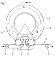
- 1 is the rotor rotating around a vertical machine axis in the direction of arrow A of a device designed as a rinser for treating bottles 2, which are fed to the device via a conveyor 3 and an inlet star 4 and which after treatment via an ejecting star and a conveyor 6 are discharged, on which the bottles 2 in turn upright, d. H. are led away with their bottom below.
- Each incoming bottle 2 is gripped and turned by a bottle gripper 7 provided on the rotor 1, so that the bottle bottom 21 finally points upwards and the bottle mouth 2 ′′ points downwards.
- This turning which takes place in a first angular range I following the inlet star 4, takes place in such a way that the respective bottle 2 is pivoted radially outward with its bottle bottom 2 '.
- the bottle 2 is treated in a further, subsequent angular range II.
- a subsequent angular range III of the rotary movement of the rotor 1 the respective bottle 2 is turned back into its original position and placed on the rotor 1.
- Curve 8 shown with a broken line, shows the vertical projection of the lower region of bottles 2 with rotating rotor 1.
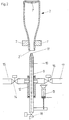
- each bottle gripper 7 is assigned a vertical nozzle tube 9 forming a treatment position.
- the nozzle tubes 9 are offset on the rotor 1 at equal angular intervals about its axis of rotation or are provided on an element (not shown) of the bottle gripper 7, so that each nozzle tube 9 is located below a bottle 2 that is gripped and turned by the associated bottle gripper 7, and in fact axially or approximately axially with the axis of the inverted bottle 2, as shown in FIG. 2.
- Each nozzle tube 9 has a nozzle channel 10 with an upper outlet or nozzle opening 11 and is displaceable in a bearing and distributor element 12 for a predetermined stroke in the vertical direction, specifically by an actuating element 13, which in the embodiment shown is formed by a pneumatic cylinder is.
- Each nozzle tube 9 is connected to a line 15 for warm water via the distributor element 12 and an individually controllable valve 14. Furthermore, each nozzle tube 9 is connected via the distributor element 12 and an individually controllable valve 18 to a line 17 for supplying steam.
- valve 2 shows at the lower end of the nozzle tube 9 a control valve 18 with which the respective nozzle tube 9 or the channel 10 there can be emptied.
- the valves 14, 16 and 18 are, for example, electrically or pneumatically operated valves.
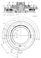
- FIG. 3 The actual design of the rotary valve 19 can be seen from FIG. 3.
- This consists of a stationary bearing part 20 with a central shaft 21 arranged thereon, which receives the upper part 22 of the rotary valve 19.
- This upper part has a multiplicity of bores 23 in which connecting hoses 24 to the individual nozzles 9 are received.
- the liquid-distributing disks 25, 26, 27 Between the upper part and the lower bearing part 20 are the liquid-distributing disks 25, 26, 27.
- the ring gears 25, 27 each have a toothing 30 on which a pinion 31 of an actuating device acts.
- a certain distance is provided for each channel 28, 29, which supplies the respective bores 23 with a certain amount of liquid. If, depending on the performance of the machine or the bottles to be treated, different amounts of media are to be discharged to the nozzles 9, a corresponding change in the media channel length is caused by motorized adjustment of a ring gear 25 or both ring gears 25, 27. For the media, you can adjust between a maximum and minimum channel length.
- the channels 28, 29 are equipped with openings, not shown, from which the medium from the bearing part 20 to the distributor disks or the channels 28, 29 and 32 arranged therein can be assigned.
- each media channel can be set separately from one another.
- the servomotor is also adjustable as a function of the speed of the rinser, so that the optimum amounts are passed to the nozzles 9 and thus to the bottles. This results in an optimal use of the media to be fed in relation to the desired cleaning and sterilizing effect.
Landscapes
- Engineering & Computer Science (AREA)
- Mechanical Engineering (AREA)
- Cleaning In General (AREA)
- Filling Of Jars Or Cans And Processes For Cleaning And Sealing Jars (AREA)
Applications Claiming Priority (2)
| Application Number | Priority Date | Filing Date | Title |
|---|---|---|---|
| DE19613267 | 1996-04-03 | ||
| DE19613267A DE19613267A1 (de) | 1996-04-03 | 1996-04-03 | Verfahren zur Überkopf-Behandlung |
Publications (3)
| Publication Number | Publication Date |
|---|---|
| EP0799652A2 true EP0799652A2 (fr) | 1997-10-08 |
| EP0799652A3 EP0799652A3 (fr) | 1998-08-12 |
| EP0799652B1 EP0799652B1 (fr) | 2001-12-19 |
Family
ID=7790330
Family Applications (1)
| Application Number | Title | Priority Date | Filing Date |
|---|---|---|---|
| EP97102191A Expired - Lifetime EP0799652B1 (fr) | 1996-04-03 | 1997-02-12 | Appareil pour le traitement col en bas de bouteilles |
Country Status (3)
| Country | Link |
|---|---|
| EP (1) | EP0799652B1 (fr) |
| BR (1) | BR9700485A (fr) |
| DE (2) | DE19613267A1 (fr) |
Cited By (4)
| Publication number | Priority date | Publication date | Assignee | Title |
|---|---|---|---|---|
| WO2005000488A1 (fr) | 2003-06-30 | 2005-01-06 | Suntory Limited | Rinceur rotatif |
| ITTO20090837A1 (it) * | 2009-10-30 | 2011-04-30 | Sidel Spa Con Socio Unico | Macchina sciacquatrice per il trattamento di contenitori, in particolare bottiglie |
| CN112774746A (zh) * | 2020-12-29 | 2021-05-11 | 深圳市天林智能科学仪器有限公司 | 一种有机测试小瓶中废液自动化处理工作站 |
| CN115739884A (zh) * | 2022-10-25 | 2023-03-07 | 湖南洪康新材料科技有限公司 | 药瓶清洗灭菌系统 |
Families Citing this family (2)
| Publication number | Priority date | Publication date | Assignee | Title |
|---|---|---|---|---|
| DE19909488A1 (de) * | 1999-03-04 | 2000-09-07 | Khs Masch & Anlagenbau Ag | Vorrichtung zur Überkopf-Behandlung von Flaschen |
| DE10010215A1 (de) * | 2000-03-02 | 2001-09-06 | Khs Masch & Anlagenbau Ag | Vorrichtung zur Überkopf-Behandlung von Flaschen oder dergleichen Behältern |
Citations (2)
| Publication number | Priority date | Publication date | Assignee | Title |
|---|---|---|---|---|
| DE3504999A1 (de) | 1984-03-26 | 1985-09-26 | Tekal s.r.l., Bergamo | Vorrichtung zum waschen und spuelen von flaschen |
| DE4229580A1 (de) | 1992-09-04 | 1994-03-10 | Seitz Enzinger Noll Masch | Verfahren und Vorrichtung zur Überkopf-Behandlung von Flaschen |
Family Cites Families (6)
| Publication number | Priority date | Publication date | Assignee | Title |
|---|---|---|---|---|
| US2418691A (en) * | 1944-03-14 | 1947-04-08 | Owens Illinois Glass Co | Machine for emptying and washing containers |
| GB1456601A (en) * | 1974-04-11 | 1976-11-24 | Le T I Im Lensoveta | Variable size orifice valve plates |
| IT1214795B (it) * | 1984-11-07 | 1990-01-18 | Enomec Srl | Mantenendo costante, anche al convogliatrice universale atta ad variare della velocita' di regime, eseguire diverse sequenze dile quantita' dei fluidi evolventi prefissate operazione tecnologiche addotti all'interno di ogni singolo contenitore in transito continuo. |
| DE3503752A1 (de) * | 1985-02-05 | 1986-08-07 | Gerhard 7520 Bruchsal Bühler | Blendenregulierventil |
| IT1259122B (it) * | 1992-06-30 | 1996-03-11 | Macchina sciacquatrice rotativa provvista di dispositivo di controllo e di distribuzione di prodotti per il trattamento di bottiglie, vasi o similari | |
| US5425385A (en) * | 1993-07-12 | 1995-06-20 | Pepsico. Inc. | Rotary washer spraying system |
-
1996
- 1996-04-03 DE DE19613267A patent/DE19613267A1/de not_active Withdrawn
-
1997
- 1997-02-12 EP EP97102191A patent/EP0799652B1/fr not_active Expired - Lifetime
- 1997-02-12 DE DE59705838T patent/DE59705838D1/de not_active Expired - Lifetime
- 1997-04-02 BR BR9700485A patent/BR9700485A/pt active Search and Examination
Patent Citations (2)
| Publication number | Priority date | Publication date | Assignee | Title |
|---|---|---|---|---|
| DE3504999A1 (de) | 1984-03-26 | 1985-09-26 | Tekal s.r.l., Bergamo | Vorrichtung zum waschen und spuelen von flaschen |
| DE4229580A1 (de) | 1992-09-04 | 1994-03-10 | Seitz Enzinger Noll Masch | Verfahren und Vorrichtung zur Überkopf-Behandlung von Flaschen |
Cited By (6)
| Publication number | Priority date | Publication date | Assignee | Title |
|---|---|---|---|---|
| WO2005000488A1 (fr) | 2003-06-30 | 2005-01-06 | Suntory Limited | Rinceur rotatif |
| EP1642656A4 (fr) * | 2003-06-30 | 2011-03-02 | Suntory Holdings Ltd | Rinceur rotatif |
| ITTO20090837A1 (it) * | 2009-10-30 | 2011-04-30 | Sidel Spa Con Socio Unico | Macchina sciacquatrice per il trattamento di contenitori, in particolare bottiglie |
| CN112774746A (zh) * | 2020-12-29 | 2021-05-11 | 深圳市天林智能科学仪器有限公司 | 一种有机测试小瓶中废液自动化处理工作站 |
| CN112774746B (zh) * | 2020-12-29 | 2022-11-15 | 深圳市天林智能科学仪器有限公司 | 一种有机测试小瓶中废液自动化处理工作站 |
| CN115739884A (zh) * | 2022-10-25 | 2023-03-07 | 湖南洪康新材料科技有限公司 | 药瓶清洗灭菌系统 |
Also Published As
| Publication number | Publication date |
|---|---|
| EP0799652A3 (fr) | 1998-08-12 |
| DE59705838D1 (de) | 2002-01-31 |
| EP0799652B1 (fr) | 2001-12-19 |
| DE19613267A1 (de) | 1997-10-09 |
| BR9700485A (pt) | 1998-11-03 |
Similar Documents
| Publication | Publication Date | Title |
|---|---|---|
| EP2035303B1 (fr) | Procede et machine de traitement de recipients | |
| EP2097184B1 (fr) | Poste de projection pour machine de nettoyage de bouteilles ou de récipients similaires et machine de nettoyage dotée d'au moins un poste de projection | |
| EP2307303B1 (fr) | Section de transport destinée à convoyer des bouchons ou des fermetures similaires servant à fermer des bouteilles ou des récipients similaires | |
| EP0303135B1 (fr) | Procédé pour le remplissage aseptique resp. stérile de récipients avec des liquides ainsi que l'installation pour la mise en oeuvre dudit procédé | |
| EP2059352B1 (fr) | Procédé pour traiter des bouteilles ou des récipients analogues dans une machine de nettoyage, et machine de nettoyage | |
| EP1820731B1 (fr) | Procédé de stérilisation de bouteilles ou récipients analogues tout comme dispositif d'exécution de ce procédé | |
| DE102009033809A1 (de) | Vorrichtung zum Behandeln von Behältnissen mit Trägersterilisation | |
| DE3918504C2 (de) | Verschließmaschine umlaufender Bauart | |
| EP2665676A1 (fr) | Élément de remplissage présentant une buse d'injection ou un ensemble buse d'injection, machine de traitement de récipients présentant une buse d'injection ou un ensemble buse d'injection et procédé de nettoyage d'éléments de machine | |
| EP3798193A1 (fr) | Dispositif de revêtement des récipients pourvu de dérivation et procédé de fonctionnement d'un tel dispositif | |
| EP0588134B1 (fr) | Méthode et dispositif de nettoyage de bouteilles en position inversées | |
| EP2332845A2 (fr) | Dispositif d'étiquetage et procédé d'étiquetage pour l'étiquetage de récipients dotés d'un dispositif de stérilisation | |
| EP0799652B1 (fr) | Appareil pour le traitement col en bas de bouteilles | |
| EP1354799B1 (fr) | Installation pour traiter des récipients d'emballage | |
| EP1048365B1 (fr) | Procédé et dispositif de nettoyage de bouteilles en position inversées | |
| WO2017021043A1 (fr) | Procédé de nettoyage et/ou de désinfection d'éléments de fermeture, machine de fermeture et élément de fermeture | |
| DE19735621A1 (de) | Verfahren und Vorrichtung zum Füllen von Behältern mit wenigstens einem dünnflüssigen bis pastösem Produkt, insbesondere unter aseptischen Bedingungen | |
| EP1129794B1 (fr) | Procédé pour le traitement col en bas de bouteilles ou conteneurs similaires | |
| DE4226616C2 (de) | Vorrichtung zur Behandlung von Behältern vor dem Befüllen | |
| DE10012909A1 (de) | Verfahren und Vorrichtung zur Reinigung von Flaschen in einer Reinigungsmaschine und zur Überkopf-Behandlung von Flaschen oder dergleichen Behälter | |
| DE29903939U1 (de) | Vorrichtung zur Überkopf-Behandlung von Flaschen | |
| DE29803902U1 (de) | Vorrichtung zur Überkopf-Behandlung von Flaschen | |
| DE102008059431A1 (de) | Vorrichtung sowie Verfahren zum Behandeln von Flaschen oder dergleichen Behältern | |
| DE9311106U1 (de) | Anlage zum sterilen Füllen und Verschließen von Flaschen o.dgl. Behälter | |
| DE975332C (de) | Vorrichtung zum Reinigen von Behaeltern, z. B. Flaschen |
Legal Events
| Date | Code | Title | Description |
|---|---|---|---|
| PUAI | Public reference made under article 153(3) epc to a published international application that has entered the european phase |
Free format text: ORIGINAL CODE: 0009012 |
|
| AK | Designated contracting states |
Kind code of ref document: A2 Designated state(s): DE FR GB IT NL |
|
| PUAL | Search report despatched |
Free format text: ORIGINAL CODE: 0009013 |
|
| AK | Designated contracting states |
Kind code of ref document: A3 Designated state(s): DE FR GB IT NL |
|
| 17P | Request for examination filed |
Effective date: 19980902 |
|
| 17Q | First examination report despatched |
Effective date: 20000522 |
|
| RTI1 | Title (correction) |
Free format text: APPARATUS FOR THE UPSIDE DOWN TREATMENT OF BOTTLES |
|
| GRAG | Despatch of communication of intention to grant |
Free format text: ORIGINAL CODE: EPIDOS AGRA |
|
| GRAG | Despatch of communication of intention to grant |
Free format text: ORIGINAL CODE: EPIDOS AGRA |
|
| GRAH | Despatch of communication of intention to grant a patent |
Free format text: ORIGINAL CODE: EPIDOS IGRA |
|
| GRAH | Despatch of communication of intention to grant a patent |
Free format text: ORIGINAL CODE: EPIDOS IGRA |
|
| ITF | It: translation for a ep patent filed | ||
| GRAA | (expected) grant |
Free format text: ORIGINAL CODE: 0009210 |
|
| AK | Designated contracting states |
Kind code of ref document: B1 Designated state(s): DE FR GB IT NL |
|
| REG | Reference to a national code |
Ref country code: GB Ref legal event code: IF02 |
|
| GBT | Gb: translation of ep patent filed (gb section 77(6)(a)/1977) |
Effective date: 20011231 |
|
| REF | Corresponds to: |
Ref document number: 59705838 Country of ref document: DE Date of ref document: 20020131 |
|
| ET | Fr: translation filed | ||
| PLBE | No opposition filed within time limit |
Free format text: ORIGINAL CODE: 0009261 |
|
| STAA | Information on the status of an ep patent application or granted ep patent |
Free format text: STATUS: NO OPPOSITION FILED WITHIN TIME LIMIT |
|
| 26N | No opposition filed | ||
| REG | Reference to a national code |
Ref country code: NL Ref legal event code: TD Effective date: 20111114 |
|
| REG | Reference to a national code |
Ref country code: FR Ref legal event code: CD Owner name: KHS GMBH Effective date: 20111122 Ref country code: FR Ref legal event code: CD Owner name: KHS GMBH Effective date: 20111121 |
|
| REG | Reference to a national code |
Ref country code: FR Ref legal event code: PLFP Year of fee payment: 20 |
|
| PGFP | Annual fee paid to national office [announced via postgrant information from national office to epo] |
Ref country code: IT Payment date: 20160223 Year of fee payment: 20 Ref country code: DE Payment date: 20160218 Year of fee payment: 20 |
|
| PGFP | Annual fee paid to national office [announced via postgrant information from national office to epo] |
Ref country code: GB Payment date: 20160217 Year of fee payment: 20 Ref country code: FR Payment date: 20160218 Year of fee payment: 20 Ref country code: NL Payment date: 20160217 Year of fee payment: 20 |
|
| REG | Reference to a national code |
Ref country code: DE Ref legal event code: R071 Ref document number: 59705838 Country of ref document: DE |
|
| REG | Reference to a national code |
Ref country code: NL Ref legal event code: MK Effective date: 20170211 |
|
| REG | Reference to a national code |
Ref country code: GB Ref legal event code: PE20 Expiry date: 20170211 |
|
| PG25 | Lapsed in a contracting state [announced via postgrant information from national office to epo] |
Ref country code: GB Free format text: LAPSE BECAUSE OF EXPIRATION OF PROTECTION Effective date: 20170211 |