EP1129794B1 - Procédé pour le traitement col en bas de bouteilles ou conteneurs similaires - Google Patents
Procédé pour le traitement col en bas de bouteilles ou conteneurs similaires Download PDFInfo
- Publication number
- EP1129794B1 EP1129794B1 EP20000127316 EP00127316A EP1129794B1 EP 1129794 B1 EP1129794 B1 EP 1129794B1 EP 20000127316 EP20000127316 EP 20000127316 EP 00127316 A EP00127316 A EP 00127316A EP 1129794 B1 EP1129794 B1 EP 1129794B1
- Authority
- EP
- European Patent Office
- Prior art keywords
- nozzle
- carrier
- rotating
- jet
- cip
- Prior art date
- Legal status (The legal status is an assumption and is not a legal conclusion. Google has not performed a legal analysis and makes no representation as to the accuracy of the status listed.)
- Expired - Lifetime
Links
- 238000004140 cleaning Methods 0.000 claims description 29
- 239000007788 liquid Substances 0.000 claims description 4
- 230000008878 coupling Effects 0.000 claims 3
- 238000010168 coupling process Methods 0.000 claims 3
- 238000005859 coupling reaction Methods 0.000 claims 3
- 230000001360 synchronised effect Effects 0.000 claims 1
- 239000007921 spray Substances 0.000 description 26
- 230000000712 assembly Effects 0.000 description 10
- 238000000429 assembly Methods 0.000 description 10
- 239000000969 carrier Substances 0.000 description 1
- 238000010276 construction Methods 0.000 description 1
- 230000001419 dependent effect Effects 0.000 description 1
- 238000001514 detection method Methods 0.000 description 1
- 238000011161 development Methods 0.000 description 1
- 230000018109 developmental process Effects 0.000 description 1
- 230000001747 exhibiting effect Effects 0.000 description 1
- 238000012986 modification Methods 0.000 description 1
- 230000004048 modification Effects 0.000 description 1
- 238000002360 preparation method Methods 0.000 description 1
- 238000007789 sealing Methods 0.000 description 1
- 238000005507 spraying Methods 0.000 description 1
- XLYOFNOQVPJJNP-UHFFFAOYSA-N water Substances O XLYOFNOQVPJJNP-UHFFFAOYSA-N 0.000 description 1
Images

Classifications
-
- B—PERFORMING OPERATIONS; TRANSPORTING
- B67—OPENING, CLOSING OR CLEANING BOTTLES, JARS OR SIMILAR CONTAINERS; LIQUID HANDLING
- B67C—CLEANING, FILLING WITH LIQUIDS OR SEMILIQUIDS, OR EMPTYING, OF BOTTLES, JARS, CANS, CASKS, BARRELS, OR SIMILAR CONTAINERS, NOT OTHERWISE PROVIDED FOR; FUNNELS
- B67C3/00—Bottling liquids or semiliquids; Filling jars or cans with liquids or semiliquids using bottling or like apparatus; Filling casks or barrels with liquids or semiliquids
- B67C3/001—Cleaning of filling devices
-
- B—PERFORMING OPERATIONS; TRANSPORTING
- B08—CLEANING
- B08B—CLEANING IN GENERAL; PREVENTION OF FOULING IN GENERAL
- B08B9/00—Cleaning hollow articles by methods or apparatus specially adapted thereto
- B08B9/08—Cleaning containers, e.g. tanks
- B08B9/20—Cleaning containers, e.g. tanks by using apparatus into or on to which containers, e.g. bottles, jars, cans are brought
- B08B9/28—Cleaning containers, e.g. tanks by using apparatus into or on to which containers, e.g. bottles, jars, cans are brought the apparatus cleaning by splash, spray, or jet application, with or without soaking
- B08B9/34—Arrangements of conduits or nozzles
Definitions
- the invention relates to a device according to the preamble of claim 1.
- Devices for the overhead treatment of bottles are known in various designs.
- devices designed in the manner of a rinser are also known (US Pat. DE 196 13 267 A1 ), in which the bottle grippers and the spray nozzles for the treatment of the bottles with the liquid and / or gaseous and / or vaporous treatment medium are provided together on the rotor rotating around the vertical machine axis.
- the transport chain is guided, inter alia, via two deflecting wheels rotating about a respective vertical axis, which are moved synchronously and in the same direction as the transport chain.
- the spray nozzles are provided such that they rotate on one of the local trajectory of bottles corresponding path and at the area enclosed by the transport chain region of the guide wheels each have a spray nozzle with its vertical nozzle axis coaxially or approximately coaxially with the vertical axis of an overhead position arranged or turned bottle lies and extends into this bottle.
- All known devices is in principle common that the bottles upright, ie fed with its axis in the vertical direction and with the bottom oriented downwards, then turned after detection by the moving or pivoting bottle gripper with this in the overhead position and this be positioned at a spray nozzle. After the overhead treatment, the bottles are turned back in their upright position, in which the bottles are drained become.
- the problem with the known devices is the CIP cleaning of the nozzles, channels for the treatment medium, etc.
- the object of the invention is to provide a device that allows trouble-free CIP cleaning, especially when rotating device.
- a device according to the patent claim 1 is formed.
- 1 is the circulating around a vertical machine axis VA in the direction of arrow A rotor of a trained as a rinser device for overhead treatment of bottles 2, the device of a conveyor 3 and an inlet star 4 upright, ie vertical with its bottle axis oriented and with fed to their bottom lying down and in turn, after treatment, standing upright via a Ausschubstern 5 and a feed dog 6 are discharged.
- Each incoming bottle 2 is provided by a provided on the rotor bottle gripper, in the Figures 2 and 3 generally indicated at 7, grasped and turned so that the bottom of each bottle faces up and the mouth of the bottle faces downwards.
- a subsequent larger angle section II of the rotational movement of the rotor the overhead treatment of the bottles held on the bottle grippers 7 and then in a further, subsequent angle section takes place in a first angle section I following the inlet star 4 III turning back the bottles 2 so that they return to their upright position.
- curve 8 of FIG. 1 shows in a vertical projection on a horizontal plane, the movement of the center of the bottle bottom of the bottle 2 with rotating rotor. 1
- each bottle gripper 7 is assigned to the rotor 1, a spray nozzle 9, in such a way that in the angle range II, the respective spray nozzle 9 extends with its nozzle opening 10 having the upper end through the bottle mouth in the turned bottle and thus with this spray nozzle the internal treatment of the bottle in question can be carried out.
- Each spray nozzle 9 is part of a nozzle assembly 11 which has a nozzle carrier 12 which is formed as an elongated, a rectangular outer cross-section exhibiting rod and is located with its longitudinal extent radially to the machine axis VA.
- the nozzle carrier is in the direction of its longitudinal axis and thus radially to the machine axis VA by a predetermined stroke (double arrow B) FIG. 2 between a working position and a cleaning position, ie, a position for the CIP cleaning slidably guided in a guide block 13 which is fixed to the upper side of the rotor 1.
- the Nozzle assemblies 11 are provided at uniform angular intervals distributed about the vertical machine axis VA.
- Each nozzle carrier 12 is provided with an inner channel connecting the spray nozzle 9 provided at the radially outer end of the nozzle carrier 12 to a port 14 attached to the radially inner end of the nozzle carrier 12, as well As the spray nozzle 9 at the top of the nozzle carrier 12.
- the terminals 14 are each connected to a terminal 16 and 17 of a rotary distributor 18.
- the rotary distributor 18 is arranged coaxially with the vertical machine axis VA and consists of a circular disk-shaped upper part 19, which is firmly connected to the rotor 1 and has the connections 16 and 17, as well as from a non-rotating with the rotor 1, on a frame of the rinser attached, also circular disk-shaped lower part 20 and a distributor disc 21.
- the terminals 16 and 17 are provided on the upper portion 19 so that all terminals 16 forming a first group of terminals, each with the relative to the axis VA radially outward distribution slot 22 and all terminals 17, a second group of terminals form, with the radially inner distributor slot 23 cooperate.
- the nozzle assemblies 11 are connected via the connecting tubes 15 to the terminals 16 and 17 so that is connected by two each of the rotor 1 adjacent nozzle assemblies 11, a nozzle assembly 11 to the terminal 16 and a nozzle assembly to the terminal 17, preferably so that for example, in the direction of rotation A of the rotor 1 following each other Nozzle assemblies 11 are alternately connected to a port 16 and to a port 17.
- the distribution slots 22 and 23 form a distribution slot pair and each have the same angular length with respect to the axis VA. If the treatment of the bottles 2 in the angular region II is carried out successively in time with a plurality of different treatment media, a plurality of distributor slot pairs or groups 22/23 formed by the distributor slots 22 and 23 are successively provided in the direction of rotation A, again with the associated connections 24 and 25.
- each manifold slot pair 22/23 are connected via a non-switchable or controllable valve device to a common source (eg, supply line, etc.) for the respective cleaning medium so that the nozzle assemblies 11 communicating with the manifold slots 22 and 23 of the respective manifold slot pair via the ports 16 and 17, respectively, are supplied with the same treatment medium.
- a common source eg, supply line, etc.
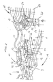
- FIG. 2 shows the nozzle assemblies 11 in their for normal operation (overhead treatment of the bottle 2) necessary working position in which the nozzle carrier 12 are moved radially outward.
- pin-shaped stop 26 which is provided in the region of the radially inner and over the guide block 13 wegêt end of each nozzle carrier 12, this working position is well defined. The stop 26 abuts against the radially inner side of the guide block 13.
- the spray nozzle 9 or its nozzle openings 10 then move in the rotating rotor 1 on the circular path 27, which is in the angular range II congruent with the local section 8 'of the curve 8.
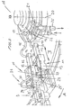
- FIG. 3 shows the nozzle carrier 12 in its radially inwardly shifted cleaning position for CIP cleaning.
- the spray nozzles 9 and their Nozzle openings 10 move here with rotating rotor 1 on in the FIG. 1 Circular path 28 designated by broken lines, which is offset radially inwards relative to the circular path 27.
- a connection cap 29 is placed, which uses a sealing ring (not shown) (O-ring) this nozzle 9 sealed to the outside with one end of a connecting hose 30 connects.
- the spray nozzles 9 of two adjacent nozzle arrangements 11 are connected to one another via the connecting hose 30 and the caps 29 provided at the two ends of this connecting hose.
- the nozzle holder 12 are radially moved inward for CIP cleaning to the extent that in particular the connecting hoses 30 are certainly outside the movement or pivoting range of the bottle gripper 7 and other functional elements or in a CIP cleaning performed with rotating machine is not, these hoses 30 with other, provided on the trajectory of the nozzle assemblies 11 functional elements, For example, collide brushes, nozzles, etc. for the treatment of the bottle outside. So it is a trouble-free CIP cleaning with rotating machine possible.
- each guide block 31 On the radially outer side, each guide block 31 has a fixed to the top of this guide block stop 32, which protrudes radially relative to the axis VA on the guide piece 13 and forms a radially outer side open fork 33, which in in the Cleaning position located nozzle carriers 12 each forms a stop for the patch on the spray nozzles 9 caps 29 and also engages behind the respective cap 29 on a projecting beyond the cap outer surface annular flange 29 ', which at the front when placed on a spray nozzle 9, open end each cap 29 is provided.
- the fork end 33 and the edge 29 ' the caps 29 are thus secured to the spray nozzles 9 against slipping.
- each guide block 13 for example, resilient locking means are still provided which cause a resilient engagement of the associated nozzle carrier 12 in the two end positions (working position and cleaning position), so that in addition to the stops 26 and 32, these positions even by the catch are clearly defined.
- the inventive design of the nozzle assemblies with the movable between the working position and the cleaning position spray nozzles 9 and nozzle holders 12 are also provided in other machines for a treatment of bottles, in which, for example, the bottle gripper on its own Transporter, for example, on a transport chain, are provided and the bottles to be treated are moved with this conveyor on a transport path, are provided on at least part of the length, for example, synchronously with the conveyor moving spray nozzles on a transport element.
Landscapes
- Engineering & Computer Science (AREA)
- Mechanical Engineering (AREA)
- Cleaning In General (AREA)
- Filling Of Jars Or Cans And Processes For Cleaning And Sealing Jars (AREA)
Claims (12)
- Dispositif pour le traitement, col en bas, de bouteilles (2) ou conteneurs similaires, en particulier rinceuse, avec plusieurs grappins à bouteille (7) prévus sur un élément de transport circulant pour entraîner des bouteilles (2) sur une voie de transport s'étendant entre une arrivée de conteneurs (4) et une sortie de conteneurs (5), voie sur laquelle les bouteilles (2) sont déplacées au moins sur une sous-section (II) dans une position col en bas, ainsi qu'avec des systèmes de buses (11) prévus sur un support circulant (1) et se succédant dans la direction de circulation (A) du support, avec à chaque fois au moins une buse de pulvérisation (9) pour la sortie d'un milieu de traitement liquide et/ou gazeux et/ou sous forme vapeur, dans lequel, dans ladite sous-section (II) de la ligne de transport (8), les buses de pulvérisation situées dans une position de travail se déplacent sur une voie de déplacement (27) correspondant à la ligne de transport (8), de préférence dans le même sens et de manière synchronisée avec les grappins à bouteilles (7), caractérisé en ce que les buses (9) peuvent être déplacées et/ou poussées pour un nettoyage en circuit fermé (CIP) depuis la position de travail transversalement ou perpendiculairement au déplacement du support (1) jusqu'à une position de nettoyage et les buses de pulvérisation (9) de deux systèmes de buses (11) voisins peuvent être reliées entre elles à chaque fois par un élément de liaison CIP (31).
- Dispositif selon la revendication 1, caractérisé en ce que les systèmes de buses (11) sont prévus répartis sur un support ou rotor (1) circulant autour d'un axe machine vertical (VA) selon des distances angulaires régulières autour de l'axe machine (VA), et en ce que les buses de pulvérisation (9) peuvent être déplacées et/ou poussées de la position de travail à la position de nettoyage vers l'extérieur ou l'intérieur par rapport à l'axe machine (VA), par exemple radialement ou approximativement radialement vers l'extérieur ou l'intérieur.
- Dispositif selon la revendication 1 ou 2, caractérisé en ce que chaque système de buse (11) présente un support de buses (12) avec la buse de pulvérisation (9) au nombre d'au moins un, et en ce que le support de buse est mobile sur un guidage (13) de la position de travail à la position de nettoyage, de préférence peut être déplacé axialement.
- Dispositif selon l'une des revendications précédentes, caractérisé en ce que l'élément de liaison CIP (31) respectif est formé par au moins un organe de liaison (30) de type tuyau ou tube et par des éléments de couplage (29) prévus aux extrémités de l'élément de liaison et pouvant être reliés chacun à une buse de pulvérisation (9).
- Dispositif selon la revendication 4, caractérisé en ce que les éléments de couplage sont des capuchons (29) pouvant être rapportés sur la buse de pulvérisation (9) respective.
- Dispositif selon l'une des revendications précédentes, caractérisé en ce que sur le système de buses (11) respectif est prévu un élément de sûreté (32, 33) qui, quand la buse de pulvérisation (9) se trouve dans la position de nettoyage, la tient sur l'élément de liaison CIP (31).
- Dispositif selon la revendication 6, caractérisé en ce que l'élément de sécurisation présente une section (33) en forme de fourche qui, dans la position de nettoyage et pour immobiliser l'élément de liaison CIP (31) sur la buse de pulvérisation (9) respective, saisit par l'arrière une butée, de préférence une saillie ou bride annulaire (29'), sur l'élément de couplage resp. sur le capuchon (29).
- Dispositif selon l'une des revendications précédentes, caractérisé en ce que les buses de pulvérisation au nombre d'au moins un de systèmes de buses (11) voisins sont raccordées par des jonctions (16, 17) séparées à des raccords (24, 25) différents pour le milieu de traitement.
- Dispositif selon la revendication 8, caractérisé, en ce que les différents raccords (24, 25) sont les raccords extérieurs d'un distributeur rotatif (18), en ce que chaque raccord extérieur (24, 25) est en liaison avec au moins un canal de distribution (22, 23) spécifique du distributeur rotatif, en ce qu'à différents canaux de distribution (22, 23) sont associés différents groupes de raccords de distributeur rotatif (16, 17), et en ce que des buses de pulvérisation voisines (9) ou systèmes de buses voisins (9) sont reliés à des raccords de distributeur rotatif (16, 17) de groupes différents.
- Dispositif selon la revendication 8, caractérisé en ce que, dans la direction de déplacement (A) du support (1), les buses de pulvérisation ou systèmes de buses sont reliées en alternance à un raccord de collecteur rotatif (16) d'un groupe ou à un raccord de collecteur rotatif (17) d'un autre groupe.
- Dispositif selon l'une des revendications précédentes, caractérisé en ce que l'élément de transport pour les grappins à bouteilles (7) est entraîné en circulation autour de l'axe machine vertical (VA).
- Dispositif selon la revendication 11, caractérisé en ce que l'élément de transport pour les grappins à bouteilles (7) et le support pour les systèmes de buses (11) sont un rotor (1) commun entraîné en circulation autour de l'axe machine (VA).
Applications Claiming Priority (2)
| Application Number | Priority Date | Filing Date | Title |
|---|---|---|---|
| DE10010215 | 2000-03-02 | ||
| DE2000110215 DE10010215A1 (de) | 2000-03-02 | 2000-03-02 | Vorrichtung zur Überkopf-Behandlung von Flaschen oder dergleichen Behältern |
Publications (3)
| Publication Number | Publication Date |
|---|---|
| EP1129794A2 EP1129794A2 (fr) | 2001-09-05 |
| EP1129794A3 EP1129794A3 (fr) | 2003-07-09 |
| EP1129794B1 true EP1129794B1 (fr) | 2008-10-01 |
Family
ID=7633265
Family Applications (1)
| Application Number | Title | Priority Date | Filing Date |
|---|---|---|---|
| EP20000127316 Expired - Lifetime EP1129794B1 (fr) | 2000-03-02 | 2000-12-13 | Procédé pour le traitement col en bas de bouteilles ou conteneurs similaires |
Country Status (2)
| Country | Link |
|---|---|
| EP (1) | EP1129794B1 (fr) |
| DE (2) | DE10010215A1 (fr) |
Families Citing this family (3)
| Publication number | Priority date | Publication date | Assignee | Title |
|---|---|---|---|---|
| DE102010063144A1 (de) * | 2010-12-15 | 2012-06-21 | Krones Aktiengesellschaft | Fluiddrehverteiler |
| DE102011008948A1 (de) * | 2011-01-19 | 2012-07-19 | Khs Gmbh | Drehverteileranordnung und Verfahren zum Betrieb ein Drehverteileranordnung |
| DE102012109643A1 (de) * | 2012-10-10 | 2014-04-10 | Krones Ag | Vorrichtung zum Behandeln von Behältern und Reinigungsverfahren für eine solche Vorrichtung |
Family Cites Families (7)
| Publication number | Priority date | Publication date | Assignee | Title |
|---|---|---|---|---|
| FR383789A (fr) * | 1907-11-09 | 1908-03-17 | Gaston Barbou Fils | Système de monture-support instantanément ajustable, pour becs de tireuses et ajutages de machines à rincer les bouteilles, ou autres machines analogues |
| CH207979A (fr) * | 1938-09-02 | 1939-12-31 | Brass Cav S A | Procédé de vidage, au moyen d'une tubulure, du liquide contenu dans le logement extérieur du fond creux des récipients placés à l'envers dans une machine à rincer. |
| DE2825562C2 (de) * | 1978-06-10 | 1986-09-11 | Holstein Und Kappert Gmbh, 4600 Dortmund | Spritzvorrichtung für Flaschenreinigungsmaschinen |
| ATE166007T1 (de) * | 1992-06-24 | 1998-05-15 | Vtz Eng & Services Ag | Verfahren, vorrichtung und maschine zum reinigen von einseitig offenen behältnissen |
| US5441063A (en) * | 1993-07-13 | 1995-08-15 | Pepsico, Inc. | High speed bottle washing machine |
| DE19613267A1 (de) * | 1996-04-03 | 1997-10-09 | Khs Masch & Anlagenbau Ag | Verfahren zur Überkopf-Behandlung |
| DE10008982A1 (de) * | 2000-02-25 | 2001-09-13 | Johann Maier | Vorrichtung zum Reinigen von Behältern |
-
2000
- 2000-03-02 DE DE2000110215 patent/DE10010215A1/de not_active Ceased
- 2000-12-13 DE DE50015379T patent/DE50015379D1/de not_active Expired - Lifetime
- 2000-12-13 EP EP20000127316 patent/EP1129794B1/fr not_active Expired - Lifetime
Also Published As
| Publication number | Publication date |
|---|---|
| EP1129794A3 (fr) | 2003-07-09 |
| EP1129794A2 (fr) | 2001-09-05 |
| DE50015379D1 (de) | 2008-11-13 |
| DE10010215A1 (de) | 2001-09-06 |
Similar Documents
| Publication | Publication Date | Title |
|---|---|---|
| EP3066043B1 (fr) | Procédé et machine de traitement de récipients | |
| EP2043944B1 (fr) | Machine de manipulation | |
| EP2059352B1 (fr) | Procédé pour traiter des bouteilles ou des récipients analogues dans une machine de nettoyage, et machine de nettoyage | |
| DE69622800T2 (de) | Anlage zum sterilen Füllen von Flaschen im Durchlaufverfahren | |
| DE1931905C3 (de) | Vorrichtung zum Zuführen eines die Luft verdrängenden Gases beim Verschließen von Behältern, insbesondere Dosen, mit Deckeln | |
| EP2035303A1 (fr) | Procédé et machine de traitement de récipients | |
| DE3124032C1 (de) | Behandlungsmaschine fuer Gegenstaende,insbesondere Etikettiermaschine oder Fueller fuer Behaelter,wie Flaschen | |
| EP0035238B1 (fr) | Machine de lavage et/ou de remplissage de récipients | |
| EP2981491B1 (fr) | Machine de traitement de contenant et procédé d'amenée et/ou d'évacuation de contenants à une machine de traitement de contenant | |
| DE3918504C2 (de) | Verschließmaschine umlaufender Bauart | |
| DE102011008878A1 (de) | Füllelement für Behälterbehandlungsmaschinen in Form von Füllmaschinen, Behälterbehandlungsmaschine sowie Verfahren zum Reinigen von Maschinenelementen an Behälterbehandlungsmaschinen | |
| WO2008055663A1 (fr) | Poste de projection pour machine de nettoyage de bouteilles ou de récipients similaires et machine de nettoyage dotée d'au moins un poste de projection | |
| EP0588134B1 (fr) | Méthode et dispositif de nettoyage de bouteilles en position inversées | |
| EP4308317A1 (fr) | Ensemble buse de pulvérisation pour un dispositif de pulvérisation, dispositif de pulvérisation doté d'un ensemble buse de pulvérisation et corps de buse pour ensemble buse de pulvérisation | |
| DE2738570C2 (fr) | ||
| EP1129794B1 (fr) | Procédé pour le traitement col en bas de bouteilles ou conteneurs similaires | |
| DE102006033511A1 (de) | Behandlungsmaschine | |
| DE69818578T2 (de) | Verfahren und Maschine zum Spülen oder Sterilisieren von Flaschen mit in die Flaschen eindringende bewegliche Düsen | |
| EP3331812B1 (fr) | Procédé de nettoyage et/ou de désinfection d'éléments de fermeture et machine de fermeture | |
| DE10012909A1 (de) | Verfahren und Vorrichtung zur Reinigung von Flaschen in einer Reinigungsmaschine und zur Überkopf-Behandlung von Flaschen oder dergleichen Behälter | |
| EP0799652B1 (fr) | Appareil pour le traitement col en bas de bouteilles | |
| DE69102399T2 (de) | Vorrichtung zum Ausgeben von flüssigen Produkten zu drehbeweglichen Teilen, insbesondere für Getränkeabfüller. | |
| DE102021106359A1 (de) | Spritzdüsenanordnung für eine Spritzstation und Düsenkörper für eine Spritzdüse einer Spritzdüsenanordnung | |
| DE10217145A1 (de) | Vorrichtung zum Behandeln von Verpackungsbehältern | |
| DE3341261C2 (fr) |
Legal Events
| Date | Code | Title | Description |
|---|---|---|---|
| PUAI | Public reference made under article 153(3) epc to a published international application that has entered the european phase |
Free format text: ORIGINAL CODE: 0009012 |
|
| AK | Designated contracting states |
Kind code of ref document: A2 Designated state(s): AT BE CH CY DE DK ES FI FR GB GR IE IT LI LU MC NL PT SE TR |
|
| AX | Request for extension of the european patent |
Free format text: AL;LT;LV;MK;RO;SI |
|
| PUAL | Search report despatched |
Free format text: ORIGINAL CODE: 0009013 |
|
| AK | Designated contracting states |
Designated state(s): AT BE CH CY DE DK ES FI FR GB GR IE IT LI LU MC NL PT SE TR |
|
| AX | Request for extension of the european patent |
Extension state: AL LT LV MK RO SI |
|
| 17P | Request for examination filed |
Effective date: 20030807 |
|
| AKX | Designation fees paid |
Designated state(s): DE FR GB IT NL |
|
| RAP1 | Party data changed (applicant data changed or rights of an application transferred) |
Owner name: KHS AG |
|
| GRAP | Despatch of communication of intention to grant a patent |
Free format text: ORIGINAL CODE: EPIDOSNIGR1 |
|
| GRAS | Grant fee paid |
Free format text: ORIGINAL CODE: EPIDOSNIGR3 |
|
| GRAA | (expected) grant |
Free format text: ORIGINAL CODE: 0009210 |
|
| AK | Designated contracting states |
Kind code of ref document: B1 Designated state(s): DE FR GB IT NL |
|
| REG | Reference to a national code |
Ref country code: GB Ref legal event code: FG4D Free format text: NOT ENGLISH |
|
| REF | Corresponds to: |
Ref document number: 50015379 Country of ref document: DE Date of ref document: 20081113 Kind code of ref document: P |
|
| PLBE | No opposition filed within time limit |
Free format text: ORIGINAL CODE: 0009261 |
|
| STAA | Information on the status of an ep patent application or granted ep patent |
Free format text: STATUS: NO OPPOSITION FILED WITHIN TIME LIMIT |
|
| 26N | No opposition filed |
Effective date: 20090702 |
|
| PGFP | Annual fee paid to national office [announced via postgrant information from national office to epo] |
Ref country code: GB Payment date: 20141219 Year of fee payment: 15 Ref country code: DE Payment date: 20141211 Year of fee payment: 15 |
|
| PGFP | Annual fee paid to national office [announced via postgrant information from national office to epo] |
Ref country code: FR Payment date: 20141219 Year of fee payment: 15 Ref country code: NL Payment date: 20141219 Year of fee payment: 15 |
|
| PGFP | Annual fee paid to national office [announced via postgrant information from national office to epo] |
Ref country code: IT Payment date: 20141223 Year of fee payment: 15 |
|
| REG | Reference to a national code |
Ref country code: DE Ref legal event code: R119 Ref document number: 50015379 Country of ref document: DE |
|
| GBPC | Gb: european patent ceased through non-payment of renewal fee |
Effective date: 20151213 |
|
| REG | Reference to a national code |
Ref country code: NL Ref legal event code: MM Effective date: 20160101 |
|
| REG | Reference to a national code |
Ref country code: FR Ref legal event code: ST Effective date: 20160831 |
|
| PG25 | Lapsed in a contracting state [announced via postgrant information from national office to epo] |
Ref country code: NL Free format text: LAPSE BECAUSE OF NON-PAYMENT OF DUE FEES Effective date: 20160101 Ref country code: DE Free format text: LAPSE BECAUSE OF NON-PAYMENT OF DUE FEES Effective date: 20160701 Ref country code: GB Free format text: LAPSE BECAUSE OF NON-PAYMENT OF DUE FEES Effective date: 20151213 |
|
| PG25 | Lapsed in a contracting state [announced via postgrant information from national office to epo] |
Ref country code: FR Free format text: LAPSE BECAUSE OF NON-PAYMENT OF DUE FEES Effective date: 20151231 |
|
| PG25 | Lapsed in a contracting state [announced via postgrant information from national office to epo] |
Ref country code: IT Free format text: LAPSE BECAUSE OF NON-PAYMENT OF DUE FEES Effective date: 20151213 |