EP0803733A1 - Messinstrument, tragbares elektronisches gerät und messverfahren - Google Patents
Messinstrument, tragbares elektronisches gerät und messverfahren Download PDFInfo
- Publication number
- EP0803733A1 EP0803733A1 EP96935372A EP96935372A EP0803733A1 EP 0803733 A1 EP0803733 A1 EP 0803733A1 EP 96935372 A EP96935372 A EP 96935372A EP 96935372 A EP96935372 A EP 96935372A EP 0803733 A1 EP0803733 A1 EP 0803733A1
- Authority
- EP
- European Patent Office
- Prior art keywords
- peak
- correction
- output value
- frequency
- side lobe
- Prior art date
- Legal status (The legal status is an assumption and is not a legal conclusion. Google has not performed a legal analysis and makes no representation as to the accuracy of the status listed.)
- Granted
Links
- 238000000034 method Methods 0.000 title claims abstract description 36
- 238000004458 analytical method Methods 0.000 claims abstract description 65
- 238000001514 detection method Methods 0.000 claims abstract description 55
- 238000012937 correction Methods 0.000 claims description 75
- 238000005259 measurement Methods 0.000 claims description 33
- 230000008569 process Effects 0.000 claims description 27
- 238000000691 measurement method Methods 0.000 claims description 19
- 238000009795 derivation Methods 0.000 claims description 18
- 238000004364 calculation method Methods 0.000 claims description 11
- 238000005070 sampling Methods 0.000 abstract description 33
- 238000001228 spectrum Methods 0.000 description 50
- 238000012545 processing Methods 0.000 description 35
- 238000010586 diagram Methods 0.000 description 17
- 239000008280 blood Substances 0.000 description 10
- 210000004369 blood Anatomy 0.000 description 10
- 239000011295 pitch Substances 0.000 description 10
- 210000000707 wrist Anatomy 0.000 description 10
- 239000004973 liquid crystal related substance Substances 0.000 description 8
- 230000008859 change Effects 0.000 description 7
- 238000013500 data storage Methods 0.000 description 4
- 238000004422 calculation algorithm Methods 0.000 description 3
- 238000007405 data analysis Methods 0.000 description 3
- 230000007246 mechanism Effects 0.000 description 3
- 101100328887 Caenorhabditis elegans col-34 gene Proteins 0.000 description 2
- 102000001554 Hemoglobins Human genes 0.000 description 2
- 108010054147 Hemoglobins Proteins 0.000 description 2
- 238000010521 absorption reaction Methods 0.000 description 2
- 230000001133 acceleration Effects 0.000 description 2
- 238000006243 chemical reaction Methods 0.000 description 2
- 230000007423 decrease Effects 0.000 description 2
- 230000000694 effects Effects 0.000 description 2
- 238000011156 evaluation Methods 0.000 description 2
- 230000005484 gravity Effects 0.000 description 2
- 238000009532 heart rate measurement Methods 0.000 description 2
- 230000009466 transformation Effects 0.000 description 2
- XUIMIQQOPSSXEZ-UHFFFAOYSA-N Silicon Chemical compound [Si] XUIMIQQOPSSXEZ-UHFFFAOYSA-N 0.000 description 1
- 101100524639 Toxoplasma gondii ROM3 gene Proteins 0.000 description 1
- 230000005540 biological transmission Effects 0.000 description 1
- 210000004204 blood vessel Anatomy 0.000 description 1
- 230000015556 catabolic process Effects 0.000 description 1
- 238000006731 degradation reaction Methods 0.000 description 1
- 238000000295 emission spectrum Methods 0.000 description 1
- 238000005516 engineering process Methods 0.000 description 1
- 239000000284 extract Substances 0.000 description 1
- 238000000605 extraction Methods 0.000 description 1
- 239000011521 glass Substances 0.000 description 1
- 229910052757 nitrogen Inorganic materials 0.000 description 1
- IJGRMHOSHXDMSA-UHFFFAOYSA-N nitrogen Substances N#N IJGRMHOSHXDMSA-UHFFFAOYSA-N 0.000 description 1
- 230000010355 oscillation Effects 0.000 description 1
- 229910052698 phosphorus Inorganic materials 0.000 description 1
- 239000011574 phosphorus Substances 0.000 description 1
- 238000003672 processing method Methods 0.000 description 1
- 229910052710 silicon Inorganic materials 0.000 description 1
- 239000010703 silicon Substances 0.000 description 1
- 238000012549 training Methods 0.000 description 1
- 210000000623 ulna Anatomy 0.000 description 1
Images


Classifications
-
- A—HUMAN NECESSITIES
- A61—MEDICAL OR VETERINARY SCIENCE; HYGIENE
- A61B—DIAGNOSIS; SURGERY; IDENTIFICATION
- A61B5/00—Measuring for diagnostic purposes; Identification of persons
- A61B5/103—Measuring devices for testing the shape, pattern, colour, size or movement of the body or parts thereof, for diagnostic purposes
- A61B5/11—Measuring movement of the entire body or parts thereof, e.g. head or hand tremor or mobility of a limb
-
- A—HUMAN NECESSITIES
- A61—MEDICAL OR VETERINARY SCIENCE; HYGIENE
- A61B—DIAGNOSIS; SURGERY; IDENTIFICATION
- A61B5/00—Measuring for diagnostic purposes; Identification of persons
- A61B5/02—Detecting, measuring or recording for evaluating the cardiovascular system, e.g. pulse, heart rate, blood pressure or blood flow
- A61B5/024—Measuring pulse rate or heart rate
- A61B5/02438—Measuring pulse rate or heart rate with portable devices, e.g. worn by the patient
-
- A—HUMAN NECESSITIES
- A61—MEDICAL OR VETERINARY SCIENCE; HYGIENE
- A61B—DIAGNOSIS; SURGERY; IDENTIFICATION
- A61B5/00—Measuring for diagnostic purposes; Identification of persons
- A61B5/68—Arrangements of detecting, measuring or recording means, e.g. sensors, in relation to patient
- A61B5/6801—Arrangements of detecting, measuring or recording means, e.g. sensors, in relation to patient specially adapted to be attached to or worn on the body surface
- A61B5/6802—Sensor mounted on worn items
- A61B5/681—Wristwatch-type devices
-
- A—HUMAN NECESSITIES
- A61—MEDICAL OR VETERINARY SCIENCE; HYGIENE
- A61B—DIAGNOSIS; SURGERY; IDENTIFICATION
- A61B5/00—Measuring for diagnostic purposes; Identification of persons
- A61B5/68—Arrangements of detecting, measuring or recording means, e.g. sensors, in relation to patient
- A61B5/6801—Arrangements of detecting, measuring or recording means, e.g. sensors, in relation to patient specially adapted to be attached to or worn on the body surface
- A61B5/6813—Specially adapted to be attached to a specific body part
- A61B5/6825—Hand
- A61B5/6826—Finger
-
- A—HUMAN NECESSITIES
- A61—MEDICAL OR VETERINARY SCIENCE; HYGIENE
- A61B—DIAGNOSIS; SURGERY; IDENTIFICATION
- A61B5/00—Measuring for diagnostic purposes; Identification of persons
- A61B5/68—Arrangements of detecting, measuring or recording means, e.g. sensors, in relation to patient
- A61B5/6801—Arrangements of detecting, measuring or recording means, e.g. sensors, in relation to patient specially adapted to be attached to or worn on the body surface
- A61B5/683—Means for maintaining contact with the body
- A61B5/6831—Straps, bands or harnesses
Definitions
- the invention relates to a measurement device and a measurement method that use a sensor to detect data that cyclically changes according to pulses or body movements, and determine cycle or frequency by analyzing the frequency of the detected value, thereby determining pulse count and body movement pitch; and more particularly, to a measurement device and a measurement method that are suitable for incorporating into or applying to small-size instruments such as portable electronic instruments.
- a method for using a sensor to detect data that cyclically changes according to factors such as pulse and movements of a body (body movements), e.g., pulse wave and acceleration, to determine pulse count or body movement pitch based on the detected data
- a method is being considered for applying frequency analysis to the data that is detected at specified tune intervals and for using the analysis result.
- frequency analysis it is possible to digitize the detected data and to apply fast Fourier transformation (FFT) using a device, such as a microprocessor, capable of digital computation; and therefore analysis can be performed at a high speed using a compact device having a simple configuration.
- FFT fast Fourier transformation
- the analysis result of the digital processing can be expressed as a group of discrete line spectrums shown in Fig. 15, for example.
- the frequency range that can be sampled is 4 Hz and if it is possible to provide a 6-bit sampling address, 64 sampling points can be obtained.
- Frequency analysis can then produce a frequency having a resolution of 1/16 Hz as the output value. For example, if a line spectrum having a peak at the 32nd address is obtained as the result of the analysis, the detected data has a frequency of 2 Hz. This translates into a pulse count measurement of 120 pulses/minute if the detected data is a pulse wave that changes according to the pulse.
- the aforementioned pulse count is 123.75 pulses/minute which would be 123 pulses/minute after digitization (integer conversion).
- the aforementioned system cannot output pulse counts between 120 and 123 pulses/minute.
- calculating a pulse count directly from the frequency of the line spectrum obtained through frequency analysis results in unnatural values and low precision.
- the aforementioned example can only provide a value based on the conversion of 1/16 Hz, which is the line spectrum interval (resolution), into a pulse count, i.e., 3.75 pulses/minute, or a value that has been turned into an integer.
- the resolution can be improved by increasing the number of sampling points, thus extending the data fetch time which is expressed as a product of sampling frequency and sampling point count.
- a change tends to lengthen the sampling time needed for accumulating sufficient data for allowing frequency analysis because pulse count and body movement pitch have low frequencies.
- a long data fetch time of around 16 seconds/cycle is required. Consequently, if the number of sampling points is increased to further extend the data fetch time, the time required for updating pulse count becomes extremely long, and as a result the pulse count that is displayed is for a fairly old measurement.
- a portable pulse counter to be worn on the arm for realtime display of pulse measurement or a portable electronic instrument equipped with a pulse-measurement function will not be able to display pulse changes on a realtime basis, making the unit inconvenient and posing a difficulty in comprehending the wearer's condition.
- PC personal computer
- the objective of this invention is to provide a measurement device and a measurement method that can provide output values, such as pulse count and body movement pitch, at high precision without increasing the number of sampling points, and thus can output more natural values.
- Another objective of the invention is to provide a measurement device and a measurement method that can process data within a short time period without extending the data fetch time or processing time by making it possible to display highly precise output values without increasing the number of sampling points, and that can output pulse count and body movement pitch on a realtime basis in a portable device or at a high speed in a processing device such as a personal computer.
- Still another objective is to provide a compact and inexpensive portable electronic instrument, in which multiple functions are incorporated in addition to pulse-count and pitch measurement functions, that can produce highly precise values using a simple configuration based on the present invention.
- the measurement device in order to obtain highly precise output values without increasing the number of sampling points, the output value indicating a peak is corrected using the side lobe values that appear on both sides of the peak value during frequency analysis.
- the measurement device has an analysis means that analyzes the frequency of cyclically changing detection data obtained from a sensor and produces the analysis result as digital data of a specified resolution, and a derivation means that derives a cycle or frequency as an output value from the analysis result, such that said derivation means can correct the output value indicating a peak in the analysis result, using a side lobe value that appears adjacent to and on at least one side of the peak, and can derive an output value of the detection data at a precision that is higher than the resolution.
- the measurement device can provide the output value of the detection data at a precision higher than the resolution without increasing the number of sampling points, it can process data and output more natural values within a short time period without extending the data fetch time or processing time. Therefore, in a portable electronic instrument that has both a control device that can process signals from a sensor and a display device that can display the output from this control device, wherein said control device is equipped with the aforementioned analysis function and a determination function, and into which other functions in addition to the function for measuring cyclical detection data can be incorporated, it is possible to output pulse count and body movement pitch values on a realtime basis and moreover to use a compact and inexpensive configuration.
- a correction method using side lobes one possible method is to perform correction while comparing the peak and side lobe intensities after converting them into patterns.
- the determination means with a correction direction determination means that identifies the side lobe to be used for correction by comparing the intensities of the side lobes on both sides of the peak, and with a correction magnitude calculation means that determines the correction magnitude by comparing the intensity of the peak with that of the side lobe identified to be used for correction and then corrects the output value indicating the peak, both the magnitude and direction of the correction can be obtained in a simple process.
- the correction magnitude calculation means uses a digital value close to the mesial magnitude of the resolution as the maximum correction magnitude and then calculates a correction magnitude using a specified function to convert the ratio of the intensity of the side lobe identified to be used for correcting the peak intensity into a digital value, and thus can determine an appropriate correction magnitude within a short time period.
- Such a method that uses a side lobe to correct the output value indicating the peak in order to determine the output value of the detection data at a high precision can be applied to cases in which detection data is analyzed in a processing device such as a personal computer. That is, the present invention can provide a measurement method having the steps described below.
- the correction process can be performed within a short time period.
- the correction magnitude calculation process uses a digital value close to the mesial magnitude of the resolution as the maximum correction magnitude and then calculates a correction magnitude using a specified function to convert the ratio of the intensity of the side lobe identified to be used for correction relative to the peak intensity into a digital value, and thus can calculate a more accurate correction magnitude within a short time period.
- Such a measurement method according to the present invention can be provided as a software program equipped with the aforementioned processes, and can be provided as a program stored in a medium such as a magnetic recording medium or ROM that can be read by a computer or microprocessor.
- Fig. 1 is a diagram showing the external appearance of a portable electronic instrument in which a pulse count measurement function using the measurement method according to the invention has been installed, and how this instrument is used.
- Fig. 2 is a block diagram showing a schematic configuration of the portable electronic instrument shown in Fig. 1.
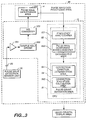
- Fig. 3 is a block diagram showing a schematic configuration of the pulse data processing area of the electronic instrument shown in Fig. 1.
- Fig. 4 is a diagram schematically showing the spectrum obtained from analyzing the frequency of a pulse signal in the pulse data processing area shown in Fig. 3.
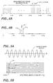
- Fig. 5 is a diagram showing the waveform of a sample wave and the result of its frequency analysis to explain the correction principle of the invention
- Fig. 5 (a) is a waveform diagram showing a sample wave of 9.0 Hz
- Fig. 5 (b) is the analysis result (spectrum) obtained from analyzing the frequency of the detection data in which the sample wave was detected.
- Fig. 6 has the same purpose as Fig. 5; Fig. 6 (a) is a waveform diagram showing a sample wave of 9.3 Hz; and Fig. 6 (b) is the analysis result (spectrum).
- Fig. 7 has the same purpose as Fig. 5; Fig. 7 (a) is a waveform diagram showing a sample wave of 9.5 Hz; and Fig. 7 (b) is the analysis result (spectrum).
- Fig. 8 has the same purpose as Fig. 5; Fig. 8 (a) is a waveform diagram showing a sample wave of 9.8 Hz; and Fig. 8 (b) is the analysis result (spectrum).
- Fig. 9 has the same purpose as Fig. 5; Fig. 9 (a) is a waveform diagram showing a sample wave of 10.0 Hz; and Fig. 9 (b) is the analysis result (spectrum).
- Fig. 10 is a graph that summarizes Fig. 5 through Fig. 9 and shows the changes in the intensities of the line spectrums that appear in the positions of 9 Hz and 10 Hz when the frequency of the sample wave is changed from 9.0 Hz to 10 Hz.
- Fig. 11 is a flow diagram showing the processing in the pulse wave data processing area of the present example.
- Fig. 12 is the top-view diagram of the device main body of the portable electronic instrument shown in Fig. 1.
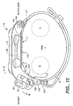
- Fig. 13 is a diagram of the device main body of the portable electronic instrument shown in Fig. 1, viewed from the 3 o'clock direction of the watch.
- Fig. 14 is a cross-section diagram of the pulse-detection sensor unit used in the portable electronic instrument shown in Fig. 1.
- Fig. 15 is a diagram showing an example of the result of frequency analysis of cyclically changing detection data.
- Fig. 1 shows a wrist-watch type portable electronic instrument equipped with the measurement function according to the invention.
- This portable electronic instrument 1 has a pulse count measurement function that can measure and display a pulse wave, in addition to a clock function that can be used as a wrist watch, and is designed such that the measurement method according to the invention can be applied when deriving a pulse count from a pulse wave.
- portable electronic instrument 1 in this embodiment is equipped with device main body 10 possessing a wristwatch structure, and this main body contains control area 5, etc. for implementing the aforementioned various functions.
- Liquid crystal display device 13 which displays various data such as time and pulse count as well as performing a user-interface function, is installed on the surface of main body 10; and furthermore, multiple operation switches 111, 112, 113, 114, 115, 116, and 117 for controlling the various functions are installed on the top and side surfaces of main body 10. Additionally, pulse wave detection sensor unit 30 is connected to main body 10 via cable 20, so that pulse waves from the finger can be detected.
- Wristband 12 which is wrapped around the wrist from the 12 o'clock direction of the wristwatch (hereafter, all directions relative to main body 10 will be indicated in terms of clock directions) and fastened in the 6 o'clock direction, is installed in said main body 10, enabling device main body 10 to be detachably mounted on the user's wrist.
- Fig. 2 shows a schematic configuration of electronic instrument 1 of this embodiment in a block diagram.
- Electronic instrument 1 of this embodiment is configured around control area 5 which comprises an element such as a microprocessor, and is provided with ROM3 which stores the programs and data necessary for processing in said control area 5, RAM4 to be used as a temporary storage area for processing and for accumulating measurement data, etc., and control area 2 for controlling control area 5.
- Control area 2 is provided with various switches 111 through 117 installed on the top or side surfaces of main body 10 as explained above.
- electronic instrument 1 of this embodiment is equipped with liquid crystal panel 13 for user interface as explained above, and said liquid crystal display device 13 displays information such as time, measured data, and processing mode.
- Electronic instrument 1 of this embodiment is additionally provided with realtime clock (RTC) unit 6 which has an oscillation function for timing, a function for measuring time of day and date, etc.; and clock processing area 60 which performs clock operations as a clock or stopwatch is configured utilizing the functions of this RTC unit 6. Additionally, electronic instrument 1 of this embodiment is equipped with pulse wave processing area 55 which can measure pulses by using control area 5 to process the signals from pulse wave sensor 30 which is connected to main body 10 via cable 20.
- RTC realtime clock
- Fig. 3 shows more details of pulse wave data processing area 55 of this embodiment.
- Pulse wave data processing area 55 of this embodiment is designed to be able to determine a pulse count based on the result that is input from pulse wave detection sensor unit 30, and to display the determined value on liquid crystal display device 13.
- pulse wave data processing area 55 of this embodiment is equipped with pulse wave detection sensor unit 30 which is mounted on a finger and can detect pulse waves as analog signals, and can provide analog signals to operation amplifier 551 of control area 5 housed inside main body 10 from said pulse wave detection sensor unit 30 via cable 20.
- the detection data of the analog signals detected by pulse wave detection sensor unit 30 is amplified by operation amplifier 551 and is sampled for each frequency by sampling hold circuit 552 of control area 5.
- the sampled result is converted into a digital signal by A/D converter 553 of control area 5 and is temporarily accumulated in pulse wave data storage area 554 of RAM4.
- the frequency of the data accumulated in said pulse wave data storage area 554 is analyzed to determine a pulse.
- a processing device to analyze the data accumulated in pulse wave data storage area 554 by transferring the data to a processing device such as a personal computer or by supplying the data via a storage medium.
- CPU51 of its control area 5 is provided with data analysis area 52 which can obtain analysis results by applying as frequency analysis, fast Fourier transformation (FFT) to the data stored in pulse wave data storage area 554, and with pulse count derivation area 54 which derives a pulse count from the analysis result.
- Data analysis area 52 is provided with frequency analysis area 52 which performs FFT processing, and with pulse wave component extraction area 53 which extracts the address and intensity of the peak and the address and intensity of the side lobe, described below, from the frequency analysis result and supplies this information to pulse count derivation area 54. Then, pulse count derivation area 54 calculates the frequency of the detection data obtained from pulse wave detection sensor unit 30, and a pulse count can be obtained from that frequency.
- FFT fast Fourier transformation
- Pulse wave data processing area 55 of this embodiment uses general-purpose sample hold circuit 552 having a sampling frequency of 8 Hz and which can use 7 bits (128 points) as the sampling address.
- 4 Hz which is equivalent to a pulse count of between 0 and 240 pulses/minute
- 64 addresses 64 sampling points
- the digital data obtained as the result of frequency analysis by cycle analysis area 521 becomes discrete data having a resolution of 1/16 Hz.
- this data is expressed as line spectrums, the result is 64 line spectrums that discretely appear at 1/16 Hz intervals as shown in Fig. 4 (a).
- pulse count derivation area 54 which derives pulse counts is provided with correction direction determination area 541 which focuses on side lobes P2 and P3 which appear adjacent to and on both sides of peak P2 and determines the direction (+ or - direction) in which to correct the frequency indicating peak P1 based on said side lobes P2 and P3, and with correction magnitude calculation area 542 which determines a correction magnitude by comparing the intensities of side lobes P2 and P3 with the intensity of peak P1, as shown in Fig. 4 (b)
- correction direction determination area 541 of this embodiment identifies the side lobe to be used for correction by comparing the intensities of side lobes P2 and P3; and the direction of the identified side lobe, e.g., side lobe P2 in Fig. 4 (b), i.e., the + direction, is determined to be the correction direction.
- Correction magnitude calculation area 542 then calculates a correction magnitude by comparing the intensity of the identified side lobe P2 with that of peak P1. If the frequency of the detection data (hereafter referred to as "original frequency") is close to side lobe P2, the position of side lobe P2 will become that of peak P1.
- the maximum value of the correction magnitude is set to a digital value close to the mesial magnitude of the resolution.
- Pulse count derivation area 54 in this embodiment is designed to output a pulse count as an integer, and the maximum correction value is set to 2 since the resolution is 3.75 pulses/minute as explained above.
- the intensity of the identified side lobe P2 is compared with that of peak P1 and the resulting ratio is designated as Rp.
- the correction value is determined using a function that produces correction value Diff of 0 if Rp is 1/4 or smaller, correction value Diff of 1 if Rp is between 1/4 and 1/2, and correction value Diff of 2 (the maximum value) if Rp is 1/2 or smaller. In this embodiment, this function is implemented using an algorithm.
- pulse count derivation area 54 Before explaining the specific processing performed by pulse count derivation area 54, an overview of the correction that can be performed using the side lobes that appear adjacent to and on both sides of the peak spectrums will be explained.
- data is sampled using a sampling method having a 1-Hz resolution to obtain frequency analysis result, in order to make the correction overview easier to explain.
- a wave whose frequency changes from 9 Hz to 10 hz is used as a sample wave. This sample wave is sampled for the specified number of sampling count and is converted into digital data. FFT processing is then applied to this digital data to produce the analysis result.
- the analysis result is shown using line spectrums which appear discretely at 1-Hz intervals.
- FIG. 5 the result of frequency analysis of the sample wave having a frequency of 9.0 Hz shown in Fig. 5 (a) is shown in Fig. 5 (b).
- Fig. 5 (b) the result of frequency analysis of the sample wave having a frequency of 9.0 Hz shown in Fig. 5 (a) is shown in Fig. 5 (b).
- line spectrum P1 showing a sharp peak appears in the 9 Hz position.
- Fig. 10 shows the data, in which a sample wave whose frequency changes from 9 Hz to 10 Hz is detected, in terms of frequency analysis output.
- This figure shows that as the frequency of the sample wave increases, the intensity of the line spectrum appearing in the 9-Hz position gradually decreases as indicated by the solid line in Fig. 10. In contrast, the intensity of the line spectrum appearing in the 10-Hz position gradually decreases as indicated by the dot-dashed line.
- the original frequency is located between the 9-Hz frequency of line spectrum P1 indicating the peak and the position of 10-Hz frequency indicating side lobe P2 which is stronger than the other side lobe P3, and thus an original frequency of 9.3 Hz can be derived.
- pulse wave data processing area 55 of this embodiment analyzes the frequency of the detection data and derives a pulse count will be explained based on the flow diagram shown in Fig. 11.
- frequency analysis (FFT) process is performed using data analysis area 52 in step ST90.
- the address indicating the peak is obtained from the result of the analysis in step ST91 and is set in variable Add which indicates the identified address.
- correction direction determination area 541 is used to determine the correction direction.
- address Add indicating the peak is multiplied by 3.75 pulses/minute which is the resolution of the pulse wave data processing area 55 of this embodiment, to obtain pulse count Pul which is the output value indicating the peak. This pulse count Pul is the value before correction.
- steps ST102 and ST103 addresses Add ⁇ 1 which come before and after address Add and which indicate side lobe addresses are specified, and the intensities of the side lobes are set in variables a and b.
- variables a and b are compared. If variable a is larger than variable b, i.e., if the intensity of the side lobe in the + direction is stronger than the intensity of the side lobe in the - direction, +1 is set in variable ⁇ which indicates a correction direction in step ST105, and additionally the intensity (variable a) of the side lobe in the + direction (on the higher frequency side) is set in variable c in step ST106.
- step ST104 determines that variable b is larger than variable a, i.e., the intensity of the side lobe in the-direction is stronger than the intensity of the side lobe in the + direction
- -1 is set in variable ⁇ in step ST107
- the intensity (variable b) of the side lobe on the - direction (on the lower frequency side) is set in variable c in step ST108.
- the above process identifies the side lobe to be used for correction and sets the correction direction.
- correction magnitude calculation area 541 is used to determine the correction magnitude and correct pulse count Pul.
- correction magnitude Diff is first cleared to 0 in step ST109.
- step ST110 the peak intensity is set in variable h using address Add, and in steps ST111 and ST112, whether the intensity (variable c) of the identified side lobe is 1/4 or less of the peak intensity (variable h), 1/4 - 1/2, or 1/2 or more is determined.
- step ST111 the value of variable c is compared with a value that is 1/4 of variable h; and if variable c is larger, 1 is set in variable Diff in step ST114.
- step ST112 the value of variable c is compared with a value that is 1/2 of variable h; and if variable c is larger, 2 is set in variable Diff in step ST115. Therefore, if variable c is less than 1/4 of variable h, variable Diff is set to 0; if variable c is equal to or larger than 1/4 of variable h but is less than 1/2 of variable h, variable Diff is set to 1; and if variable c is equal to or larger than 1/2 of variable h, variable Diff is set to 2.
- pulse count Pul corresponding to the peak address is corrected in step ST113; and if side lobes are present, pulse count Pul that is shifted toward the side lobe with a larger intensity can be obtained.
- pulse wave data processing area 55 of this embodiment is designed to compare the peak intensity and the side lobe intensities whose frequencies have been analyzed, and to use the comparison result to correct the frequency indicating the peak, in order to derive a frequency that is closer to the original frequency.
- no correction is performed if the intensity of the side lobe to be used for correction is 1/4 or less of the peak intensity, and correction of ⁇ 1 is performed depending on the direction of the side lobe to be used for correction if the side lobe intensity is in the range of 1/4 to 1/2 of the peak intensity.
- Correction of ⁇ 2 is performed if the side lobe intensity exceeds 1/2 of the peak intensity. Therefore, even though the resolution of the pulse count obtained as the result of the frequency analysis is as coarse as 3.75 pulses/minute, the correction can produce an extremely precise pulse count with a resolution of 1 pulse/minute and a precision of ⁇ 0.5 pulses/minute.
- the function (algorithm) for obtaining correction magnitude is not limited to that described above, and it is possible to calculate the correction magnitude by substituting the ratio between the peak intensity and side lobe intensity into a certain equation, instead of using an algorithm for evaluation.
- values other than 1/2 or 1/4, such as 1/3 and 2/3 for the intensity evaluation value can be used for evaluating the peak intensity and side lobe intensities.
- a tool such as a patterned table can also be used for evaluating the peak intensity and side lobe intensities
- the use of the aforementioned processing method can produce sufficiently precise output values within a short time period.
- the present invention can produce sufficiently precise output values, natural and reasonable values can be displayed even when output values must be displayed continuously.
- pulse wave data processing area 55 of this embodiment can improve the precision of pulse counts which are output values, without increasing the number of sampling points, highly precise pulse counts can be displayed without extending the data fetch time. Moreover, since the sampling count does not increase, the time required for FFT processing does not increase, and thus highly precise pulse counts can be calculated at high speeds. Therefore, by detecting pulse waves by mounting wristwatch-type electronic instrument 1 of this embodiment on the user's wrist, pulse counts can be displayed on electronic instrument 1 on a realtime basis, and it becomes possible to closely monitor pulse counts while the wearer is engaged in a marathon, walking, or training, and thus to understand one's own physical condition and adjust the exercise accordingly.
- the measurement device and measurement method according to the invention do not increase sampling counts, highly precise measurements can be made using a general-purpose type or a small and compact type with a limited number of addresses for the processing mechanism such as the sample hold circuit that processes pulse waves. Therefore, the invention enables even a small and inexpensive measurement device to provide precise measurement results.
- Pulse wave data processing area 55 equipped with the functions described above can be implemented as one of the functions of multi-function electronic instrument 1 as in this embodiment, or can be provided as a pulse wave counter equipped with a single function for measuring pulse waves.
- the pulse count determination process explained based on Fig. 11 can of course be implemented as a software program when analyzing pulse wave data using a personal computer, etc.
- a software program utilizing the measurement method according to the invention can obtain the original frequency or cycle at a high speed and excellent precision from data with a relatively small sampling count, and thus can be applied to various analysis programs.
- Such a software program can be provided as a program stored in a medium such as a floppy disk, hard disk, magnetic recording medium, CD, and ROM that can be read by a computer or microprocessor.
- the measurement device and measurement method according to the invention are of course not limited in their application to devices that measure pulse waves.
- the device and the method can be applied to measuring body movement pitches using an acceleration sensor, and can be used to obtain output values such as the frequency and cycle of other cyclically changing data at high precision using small sampling counts.
- the measurement device and measurement method according to the invention need only a small sampling count, they are extremely suitable to measuring low-frequency data that requires long sampling time, and are suitable to measuring data related to the human body, such as number of breaths, in addition to pulse count and body movement pitch described above.
- pulse wave detection sensor unit 30 is connected via cable 20 to main body 10 of portable electronic instrument 1 in this embodiment, having the wristwatch structure.
- Connector piece 80 is provided on the tip side of cable 20, and said connector piece 80 can be detachably installed in connector area 70 provided on the 6 o'clock side of device main body 10.
- Pulse wave detection sensor unit 30 is attached to the area between the base and the first joint of the index finger and is shielded from light by sensor-fastening strap 40. Attaching pulse wave detection sensor unit 30 to the base of a finger in this way keeps cable 20 short and prevents it from getting in the way during running.
- the temperature at the finger tip falls substantially, while the temperature at the base of the finger falls relatively little. Therefore, attaching pulse wave detection sensor unit 30 at the base of the finger enables pulse count, etc. to be accurately measured even during a run outside on a cold day.
- Fig. 12 shows main body 10 of the portable electronic instrument of this embodiment, with the wristband and cable removed;
- Fig. 13 shows a view of portable electronic instrument, obtained from the 3 o'clock direction of the main body.
- device main body 10 of this embodiment is provided with plastic watch case 11 (body case), and the top side of this watch case 11 is provided with liquid crystal display device 13 (display device) with an EL backlight for displaying running time, pitch during walking, and pulse wave information such as pulse count, in addition to current time and date.
- Liquid crystal display device 13 is provided with first segment display area 131 positioned on the upper left side of the display surface, second segment display area 132 positioned on the upper right side of the display surface, third segment display area 133 positioned on the lower right side of the display surface, and dot display area 134 positioned on the lower left side of the display. Dot display area 134 can graphically display various types of information.
- control area 5 which performs various types of control and data processing in order to determine the change in pulse count based on the data detected by pulse wave detection sensor unit 30 and to display the result on liquid crystal display device 13, is provided inside watch case 11.
- Control area 5 is also provided with a timing circuit and thus can display normal time, lap time, split time, etc. on liquid crystal display device 13.
- Button switches 111 through 115 which are used for external operations such as time adjustment and display mode switching, are provided on the perimeter of watch case 11. Additionally, larger button switches 116 and 117 are provided on the surface of the watch case. Furthermore, button-shaped small battery 59 which acts as the power supply for portable electronic instrument 1 is housed inside watch case 11, and electrical power can also be supplied from battery 59 to pulse wave detection sensor unit 30 via cable 20. This cable 20 is also used for inputting the detection result of pulse wave detection sensor unit 30 into control area 5 of watch case 11.
- portable electronic instrument 1 of this embodiment is a multi-function device
- the size of device main body 10 must be increased as more functions are added.
- watch case 11 is extended in the 3 and 9 o'clock directions
- wristband 12 is connected eccentrically toward the 3 o'clock side, leaving large extended area 101 in the 9 o'clock direction of the wristwatch, viewed from wristband 12.
- no such extended area is provided in the 3 o'clock direction. Consequently, this structure, despite the use of long watch case 11, allows free wrist movement and eliminates the possibility of the back of the hand striking watch case 11 during a fall.
- Flat piezoelectric element 58 for a buzzer is positioned in the 9 o'clock direction, viewed from battery 59, inside watch case 11.
- Battery 59 which is heavier than piezoelectric element 58 is positioned eccentrically in the 3 o'clock direction so that the center of gravity of device main body 10 is shifted in the 3 o'clock direction. Because wristband 12 is connected to a spot near this center of gravity, device main body 10 can be securely attached to the wrist.
- the positioning of battery 59 and piezoelectric element 58 in the planar direction allows device main body 10 to be thin, and battery cover 118 installed on the back side as shown in Fig. 13 allows the user to easily replace battery 59.
- connecting area 105 for holding stopping pin 121 installed on the end of wristband 12 is formed in the 12 o'clock direction of watch case 11.
- Receiving area 106 is provided in the 6 o'clock direction of watch case 11, and fastener 122 for holding in place the middle point of wristband 12 wound around the wrist and folded back in the longitudinal direction of the band, is formed on said receiving area 106.
- the area from bottom surface 119 to receiving area 106 is formed as an integral part of watch case 11 and forms rotation stop area 108 which is positioned at approximately 115° from bottom surface 119. That is, when wristband 12 is used to attach device main body 10 to top area L1 (side of the back of the hand) of right wrist L (arm), bottom surface 119 of watch case 11 tightly contacts top area L1 of wrist L while rotation stop area 108 contacts side area L2 where radius R is located. In this state, bottom surface 119 of device main body 10 more or less straddles radius R and ulna U, while rotation stop area 108 and the area between bent area 109 of bottom surface 119 and rotation stop area 108 contact radius R.
- rotation stop area 108 and bottom surface 119 form an anatomically ideal angle of approximately 115° as explained above, device main body 10 will not turn around arm L even if an attempt is made to turn it in the direction of arrow A or B. Furthermore, because the rotation of device main body 10 is restricted only in two locations on the side of the arm by bottom surface 119 and rotation stop area 108, bottom surface 119 and rotation stop area 108 securely contact the am even if it is thin, and provide a secure rotation stopping effect and comfortable fit even if the arm is thick.
- Fig. 14 shows a cross-section of the pulse wave detection sensor unit of this embodiment.
- component housing space 300 is formed by placing back lid 302 on the bottom side of sensor frame 36 which constitutes a casing body.
- Circuit board 35 is positioned inside component housing space 300.
- LED 31, phototransistor 32, and other electronic components are mounted on circuit board 35.
- One end of cable 20 is fastened to pulse wave detection sensor unit 30 by bushing 393, and various wires of cable 20 are soldered to various patterns on circuit board 35.
- pulse wave detection sensor unit 30 is attached to the finger such that cable 20 is extended from the base of the finger toward device main body 10.
- LED 31 and phototransistor 32 are arranged along the length of the finger, with LED 31 positioned on the finger tip side and phototransistor 32 positioned at the base of the finger. This configuration provides the effect of making it difficult for the ambient light to reach phototransistor 32.
- a light transmission window is formed by translucent plate 34 which is made of a glass plate on the upper area of sensor frame 36, and the light-emitting surface and light-receiving surface of LED 31 and phototransistor 32, respectively, are oriented toward said translucent plate 34 . Because of such a configuration, when a finger surface is pressed onto external surface 341 of translucent plate 34, LED 31 emits light toward the finger surface and phototransistor 32 can receive part of the light emitted by LED 31 that is reflected by the finger. Note that external surface 341 of translucent plate 34 protrudes farther than surrounding area 361 in order to improve its contact with the finger surface.
- an InGaN (indium-gallium-nitrogen) blue LED is used as LED 31, and its emission spectrum possesses a peak at 450 nm and its emission wavelength ranges from 350 to 600 nm.
- a GaAsP (gallium-arsenic-phosphorus) phototransistor is used as phototransistor 32, and the light-receiving wavelength of the element itself ranges from 300 to 600 nm, with some sensitive areas also at or below 300 nm.
- pulse wave detection sensor unit 30 When pulse wave detection sensor unit 30 thus configured is attached to the base of the finger by sensor-fastening strap 40 and light is emitted from LED 31 toward the finger, the light reaches blood vessels, and part of the light is absorbed by the hemoglobin in the blood and part of it is reflected.
- the light reflected by the finger (blood) is received by phototransistor 32, and the change in the amount of received light corresponds to the change in the blood volume (pulse wave in the blood). That is, because the reflected light becomes weak when the blood volume is high and becomes strong when the blood volume is low, data such as pulse count can be measured by optically detecting the intensity of the reflected light as a pulse wave signal.
- This embodiment uses LED 31 with an emission wavelength range of between 350 and 600 nm and phototransistor 32 with a light-receiving wavelength range of between 300 and 600 nm, and vital information is displayed based on the results taken in the overlapping wavelengths of between approximately 300 and approximately 600 nm, i.e., wavelengths of approximately 700 nm or shorter.
- pulse wave detection sensor unit 30 Even if the ambient light strikes the exposed part of the finger, lights with wavelengths of 700 nm or shorter contained in the ambient light do not use the finger as a light guide to reach phototransistor 32 (light-receiving area). The reason for this is as follows.
- the S/N ratio of the pulse wave signal based on blood volume change is high.
- the reason for this is as follows.
- the absorption coefficient of hemoglobin in the blood for lights with wavelengths of between 300 and 700 nm is several times to approximately one hundred or more times larger than the absorption coefficient for a light with wavelength of 800 nm which has been conventionally used as the detection light.
- lights with wavelengths of between 300 and 700 nm change sensitively to blood volume changes, producing higher pulse wave detection rate (S/N ratio) based on blood volume change.
- the measurement device and measurement method according to the present invention correct output values, such as pulse counts indicating the peak obtained through frequency analysis, using the side lobe values that appear on both sides of the peak, and thus can provide highly precise output values without increasing the number of sampling points. Consequently, the invention can provide highly precise output values without extending the data fetch time or tightening the specification of the measurement device. Therefore, the measurement device and measurement method according to the invention are ideal for portable, compact, multi-function electronic instruments which use digital measurement processes, and can be applied to a wide variety of measurements in the future.
- the present invention relates to a measurement device and a measurement method that measure cyclically changing data, such as pulse wave, and produce output values such as pulse count. Because the invention can improve the precision of the output values without increasing the sampling count, it is ideal for portable, compact, multi-function electronic instruments equipped with functions such as pulse count measurement function.
Landscapes
- Health & Medical Sciences (AREA)
- Life Sciences & Earth Sciences (AREA)
- Heart & Thoracic Surgery (AREA)
- Medical Informatics (AREA)
- Physics & Mathematics (AREA)
- Cardiology (AREA)
- Biophysics (AREA)
- Pathology (AREA)
- Engineering & Computer Science (AREA)
- Biomedical Technology (AREA)
- Physiology (AREA)
- Veterinary Medicine (AREA)
- Molecular Biology (AREA)
- Surgery (AREA)
- Animal Behavior & Ethology (AREA)
- General Health & Medical Sciences (AREA)
- Public Health (AREA)
- Oral & Maxillofacial Surgery (AREA)
- Dentistry (AREA)
- Measuring Pulse, Heart Rate, Blood Pressure Or Blood Flow (AREA)
- Electric Clocks (AREA)
Applications Claiming Priority (4)
| Application Number | Priority Date | Filing Date | Title |
|---|---|---|---|
| JP2703/95 | 1995-10-18 | ||
| JP27039595A JP3454989B2 (ja) | 1995-10-18 | 1995-10-18 | 計測データに対する補正方法 |
| JP27039595 | 1995-10-18 | ||
| PCT/JP1996/003033 WO1997014971A1 (en) | 1995-10-18 | 1996-10-18 | Measuring instrument, portable electronic equipment and measuring method |
Publications (3)
| Publication Number | Publication Date |
|---|---|
| EP0803733A1 true EP0803733A1 (de) | 1997-10-29 |
| EP0803733A4 EP0803733A4 (de) | 1999-02-17 |
| EP0803733B1 EP0803733B1 (de) | 2003-12-10 |
Family
ID=17485668
Family Applications (1)
| Application Number | Title | Priority Date | Filing Date |
|---|---|---|---|
| EP96935372A Expired - Lifetime EP0803733B1 (de) | 1995-10-18 | 1996-10-18 | Messinstrument, tragbares elektronisches gerät und messverfahren |
Country Status (5)
| Country | Link |
|---|---|
| US (1) | US6023662A (de) |
| EP (1) | EP0803733B1 (de) |
| JP (1) | JP3454989B2 (de) |
| DE (1) | DE69631033T2 (de) |
| WO (1) | WO1997014971A1 (de) |
Cited By (1)
| Publication number | Priority date | Publication date | Assignee | Title |
|---|---|---|---|---|
| WO1999038018A1 (de) * | 1998-01-22 | 1999-07-29 | Daimlerchrysler Aerospace Ag | Verfahren zur schätzung der frequenz eines zeitsignals |
Families Citing this family (7)
| Publication number | Priority date | Publication date | Assignee | Title |
|---|---|---|---|---|
| AU2001290292A1 (en) * | 2000-10-31 | 2002-05-15 | Takeshi Sahashi | Body movement analysis system and body movement analysis method |
| US7993276B2 (en) | 2004-10-15 | 2011-08-09 | Pulse Tracer, Inc. | Motion cancellation of optical input signals for physiological pulse measurement |
| US7745381B2 (en) * | 2005-03-15 | 2010-06-29 | Ecolab Inc. | Lubricant for conveying containers |
| JP4069929B2 (ja) * | 2005-04-06 | 2008-04-02 | コニカミノルタセンシング株式会社 | 生体情報処理装置 |
| US20070276277A1 (en) * | 2006-05-24 | 2007-11-29 | John Booth | Device and method of manual measurement of pulse or respiratory rate |
| JP5713595B2 (ja) * | 2010-07-16 | 2015-05-07 | オムロンヘルスケア株式会社 | 運動検出装置、および、運動検出装置の制御方法 |
| TW201249399A (en) * | 2011-06-09 | 2012-12-16 | Hon Hai Prec Ind Co Ltd | Electronic apparatus and detecting pulse method thereof |
Family Cites Families (7)
| Publication number | Priority date | Publication date | Assignee | Title |
|---|---|---|---|---|
| JPS63210671A (ja) * | 1987-02-27 | 1988-09-01 | Nec Corp | 信号パワ−測定装置 |
| JP2808954B2 (ja) * | 1991-11-13 | 1998-10-08 | 国際電信電話株式会社 | 無変調信号検出及び周波数引き込み装置 |
| JPH05256883A (ja) * | 1992-03-14 | 1993-10-08 | Toyo Commun Equip Co Ltd | デジタル周波数分析方法及び装置 |
| JP3220271B2 (ja) * | 1993-02-22 | 2001-10-22 | セイコーインスツルメンツ株式会社 | 脈拍計付歩数計 |
| JP2816944B2 (ja) * | 1993-12-20 | 1998-10-27 | セイコーインスツルメンツ株式会社 | 脈拍計 |
| JP3605216B2 (ja) * | 1995-02-20 | 2004-12-22 | セイコーエプソン株式会社 | 脈拍計 |
| JP3492086B2 (ja) * | 1995-06-30 | 2004-02-03 | セイコーエプソン株式会社 | 腕装着型脈波計測機器および脈波情報処理装置 |
-
1995
- 1995-10-18 JP JP27039595A patent/JP3454989B2/ja not_active Expired - Lifetime
-
1996
- 1996-10-18 WO PCT/JP1996/003033 patent/WO1997014971A1/ja not_active Ceased
- 1996-10-18 EP EP96935372A patent/EP0803733B1/de not_active Expired - Lifetime
- 1996-10-18 DE DE69631033T patent/DE69631033T2/de not_active Expired - Lifetime
- 1996-10-18 US US08/849,877 patent/US6023662A/en not_active Expired - Lifetime
Cited By (2)
| Publication number | Priority date | Publication date | Assignee | Title |
|---|---|---|---|---|
| WO1999038018A1 (de) * | 1998-01-22 | 1999-07-29 | Daimlerchrysler Aerospace Ag | Verfahren zur schätzung der frequenz eines zeitsignals |
| US6484112B1 (en) | 1998-01-22 | 2002-11-19 | Eads Deutschland Gmbh | Method for estimating the frequency of a time signal |
Also Published As
| Publication number | Publication date |
|---|---|
| JPH09108193A (ja) | 1997-04-28 |
| WO1997014971A1 (en) | 1997-04-24 |
| DE69631033D1 (de) | 2004-01-22 |
| JP3454989B2 (ja) | 2003-10-06 |
| DE69631033T2 (de) | 2004-12-30 |
| EP0803733B1 (de) | 2003-12-10 |
| US6023662A (en) | 2000-02-08 |
| EP0803733A4 (de) | 1999-02-17 |
Similar Documents
| Publication | Publication Date | Title |
|---|---|---|
| EP0729726B1 (de) | Pulsschlagmesser | |
| EP0805414B1 (de) | Schrittmessvorrichtung, elektronisches gerät und schrittmessverfahren | |
| US7144375B2 (en) | Pulsimeter, control method for pulsimeter, wristwatch information device, control program, and recording medium | |
| US6099478A (en) | Pulse counter and pulse display method | |
| US5759156A (en) | Period and frequency measurement device with correction device and method thereof | |
| JP3492086B2 (ja) | 腕装着型脈波計測機器および脈波情報処理装置 | |
| US6155983A (en) | Pulse wave detecting device and pulse measurer | |
| US20060195020A1 (en) | Methods, systems, and apparatus for measuring a pulse rate | |
| EP2859842A1 (de) | Reflektive Photodetektionsvorrichtung und Vorrichtung zur Messung biologischer Informationen | |
| WO2007072239A3 (en) | Apparatus for monitoring a person's heart rate and/or heart rate variation; wristwatch comprising the same | |
| JPH11276448A (ja) | 信号抽出装置および信号抽出方法 | |
| US20030144596A1 (en) | Strap structure and a biological information sensing device using the same | |
| US6023662A (en) | Measurement device, portable electronic instrument, and measurement method | |
| EP0762296B1 (de) | Einheit und Gerät zur schnellen Fourier-Transformationsberechnung | |
| JP5012866B2 (ja) | 生体情報処理装置、および、生体情報処理方法 | |
| JP3564255B2 (ja) | 脈拍計 | |
| JP3420409B2 (ja) | 計測装置 | |
| US20210116870A1 (en) | Measuring device for a mechanical watch | |
| JP2004113821A (ja) | 運動処方支援装置 | |
| HK1014475A (en) | Pulse rate meter | |
| JP2005137677A (ja) | 計測装置、計測装置の制御方法、制御プログラムおよび記録媒体 | |
| JPH09135818A (ja) | 携帯用電子機器 | |
| JPH09113653A (ja) | 周期・周波数計測装置 | |
| JP2005218500A (ja) | 手首装着型脈拍測定装置 | |
| HK1014775A (en) | A fast fourier transformation computing unit and fast fourier transformation computation device |
Legal Events
| Date | Code | Title | Description |
|---|---|---|---|
| PUAI | Public reference made under article 153(3) epc to a published international application that has entered the european phase |
Free format text: ORIGINAL CODE: 0009012 |
|
| PUAB | Information related to the publication of an a document modified or deleted |
Free format text: ORIGINAL CODE: 0009199EPPU |
|
| PUAF | Information related to the publication of a search report (a3 document) modified or deleted |
Free format text: ORIGINAL CODE: 0009199SEPU |
|
| PUAI | Public reference made under article 153(3) epc to a published international application that has entered the european phase |
Free format text: ORIGINAL CODE: 0009012 |
|
| AK | Designated contracting states |
Kind code of ref document: A1 Designated state(s): DE FI FR GB |
|
| 17P | Request for examination filed |
Effective date: 19971022 |
|
| A4 | Supplementary search report drawn up and despatched |
Effective date: 19990107 |
|
| AK | Designated contracting states |
Kind code of ref document: A4 Designated state(s): DE FI FR GB |
|
| 17Q | First examination report despatched |
Effective date: 20020322 |
|
| GRAH | Despatch of communication of intention to grant a patent |
Free format text: ORIGINAL CODE: EPIDOS IGRA |
|
| GRAS | Grant fee paid |
Free format text: ORIGINAL CODE: EPIDOSNIGR3 |
|
| GRAA | (expected) grant |
Free format text: ORIGINAL CODE: 0009210 |
|
| AK | Designated contracting states |
Kind code of ref document: B1 Designated state(s): DE FI FR GB |
|
| REG | Reference to a national code |
Ref country code: GB Ref legal event code: FG4D |
|
| REF | Corresponds to: |
Ref document number: 69631033 Country of ref document: DE Date of ref document: 20040122 Kind code of ref document: P |
|
| ET | Fr: translation filed | ||
| PLBE | No opposition filed within time limit |
Free format text: ORIGINAL CODE: 0009261 |
|
| STAA | Information on the status of an ep patent application or granted ep patent |
Free format text: STATUS: NO OPPOSITION FILED WITHIN TIME LIMIT |
|
| 26N | No opposition filed |
Effective date: 20040913 |
|
| REG | Reference to a national code |
Ref country code: FR Ref legal event code: PLFP Year of fee payment: 20 |
|
| PGFP | Annual fee paid to national office [announced via postgrant information from national office to epo] |
Ref country code: FR Payment date: 20150908 Year of fee payment: 20 |
|
| PGFP | Annual fee paid to national office [announced via postgrant information from national office to epo] |
Ref country code: DE Payment date: 20151013 Year of fee payment: 20 Ref country code: FI Payment date: 20151012 Year of fee payment: 20 Ref country code: GB Payment date: 20151014 Year of fee payment: 20 |
|
| REG | Reference to a national code |
Ref country code: DE Ref legal event code: R071 Ref document number: 69631033 Country of ref document: DE |
|
| REG | Reference to a national code |
Ref country code: GB Ref legal event code: PE20 Expiry date: 20161017 |
|
| PG25 | Lapsed in a contracting state [announced via postgrant information from national office to epo] |
Ref country code: GB Free format text: LAPSE BECAUSE OF EXPIRATION OF PROTECTION Effective date: 20161017 |