EP0807552A1 - Mécanisme pour fixer et détacher un téléphone portatif sans fil dans un véhicule - Google Patents
Mécanisme pour fixer et détacher un téléphone portatif sans fil dans un véhicule Download PDFInfo
- Publication number
- EP0807552A1 EP0807552A1 EP97107826A EP97107826A EP0807552A1 EP 0807552 A1 EP0807552 A1 EP 0807552A1 EP 97107826 A EP97107826 A EP 97107826A EP 97107826 A EP97107826 A EP 97107826A EP 0807552 A1 EP0807552 A1 EP 0807552A1
- Authority
- EP
- European Patent Office
- Prior art keywords
- holder
- cordless telephone
- telephone
- portable cordless
- gear
- Prior art date
- Legal status (The legal status is an assumption and is not a legal conclusion. Google has not performed a legal analysis and makes no representation as to the accuracy of the status listed.)
- Granted
Links
- 230000007246 mechanism Effects 0.000 title claims abstract description 36
- 230000009471 action Effects 0.000 claims abstract description 3
- 230000003068 static effect Effects 0.000 claims description 7
- 230000000694 effects Effects 0.000 description 3
- 239000004973 liquid crystal related substance Substances 0.000 description 2
- 229920003002 synthetic resin Polymers 0.000 description 2
- 239000000057 synthetic resin Substances 0.000 description 2
- 238000005452 bending Methods 0.000 description 1
- 238000004891 communication Methods 0.000 description 1
- 230000006872 improvement Effects 0.000 description 1
- 239000000463 material Substances 0.000 description 1
- 239000002184 metal Substances 0.000 description 1
- 238000000034 method Methods 0.000 description 1
- 238000012986 modification Methods 0.000 description 1
- 230000004048 modification Effects 0.000 description 1
- 230000008569 process Effects 0.000 description 1
- 238000004080 punching Methods 0.000 description 1
Images


Classifications
-
- B—PERFORMING OPERATIONS; TRANSPORTING
- B60—VEHICLES IN GENERAL
- B60R—VEHICLES, VEHICLE FITTINGS, OR VEHICLE PARTS, NOT OTHERWISE PROVIDED FOR
- B60R11/00—Arrangements for holding or mounting articles, not otherwise provided for
- B60R11/02—Arrangements for holding or mounting articles, not otherwise provided for for radio sets, television sets, telephones, or the like; Arrangement of controls thereof
- B60R11/0241—Arrangements for holding or mounting articles, not otherwise provided for for radio sets, television sets, telephones, or the like; Arrangement of controls thereof for telephones
-
- B—PERFORMING OPERATIONS; TRANSPORTING
- B60—VEHICLES IN GENERAL
- B60R—VEHICLES, VEHICLE FITTINGS, OR VEHICLE PARTS, NOT OTHERWISE PROVIDED FOR
- B60R11/00—Arrangements for holding or mounting articles, not otherwise provided for
- B60R2011/0001—Arrangements for holding or mounting articles, not otherwise provided for characterised by position
- B60R2011/0003—Arrangements for holding or mounting articles, not otherwise provided for characterised by position inside the vehicle
- B60R2011/0005—Dashboard
-
- B—PERFORMING OPERATIONS; TRANSPORTING
- B60—VEHICLES IN GENERAL
- B60R—VEHICLES, VEHICLE FITTINGS, OR VEHICLE PARTS, NOT OTHERWISE PROVIDED FOR
- B60R11/00—Arrangements for holding or mounting articles, not otherwise provided for
- B60R2011/0042—Arrangements for holding or mounting articles, not otherwise provided for characterised by mounting means
- B60R2011/0043—Arrangements for holding or mounting articles, not otherwise provided for characterised by mounting means for integrated articles, i.e. not substantially protruding from the surrounding parts
- B60R2011/0045—Arrangements for holding or mounting articles, not otherwise provided for characterised by mounting means for integrated articles, i.e. not substantially protruding from the surrounding parts with visible part, e.g. flush mounted
- B60R2011/0047—Arrangements for holding or mounting articles, not otherwise provided for characterised by mounting means for integrated articles, i.e. not substantially protruding from the surrounding parts with visible part, e.g. flush mounted using hidden fastening means
Definitions
- the present invention relates to a mechanism for attaching and detaching an electronic instrument (such as a portable cordless telephone) in a motor vehicle, or a mechanism for attaching and detaching an operating section of an electronic instrument to the main body thereof in a motor vehicle.
- an electronic instrument such as a portable cordless telephone
- a motor vehicle may be provided with a portable cordless telephone.
- a portable cordless telephone usually includes a wireless handset having a plurality of push-buttons. A user may perform his desired wireless communication with a person far away from the motor vehicle simply by pushing push-buttons on the cordless handset.
- Fig. 8 illustrates a condition in which a center console 102 is provided between a driver seat and a passenger seat in a vehicle room, a portable cordless telephone 105 is attached onto the center console 102.
- the center console 102 is provided with a telephone adaptor 103 having a connector 104, and a connector 106 of the portable cordless telephone 105 is inserted into the connector 104 in a direction shown by an arrow G , thereby completing a predetermined electric connection between the two connectors 104 and 106.
- the portable cordless telephone 105 may be easily attached and held on the telephone adaptor 103.
- a display panel be provided on the surface of a handset of a portable cordless telephone, so that when the telephone is connected in its predetermined position, a telephone number to be used to make a phone call may be displayed on the display panel. Further, the display panel may also be constructed to become a touch-panel to in advance selectively input telephone number (to make a phone call) on the display panel.
- the display panel When the above-described portable cordless telephone having a display panel is mounted in a motor vehicle, it is required that the display panel be positioned in a position so that both the driver and the passenger sitting beside the driver can easily see the display panel. At least, the display panel should be disposed not to hamper the driver's operation of the motor vehicle. Preferably, the display panel is positioned close to a dashboard in front of the driver's seat.
- an optional console for deeply mounting a stereo equipment may also be used to mount a display panel of a portable cordless telephone, in a manner such that the main body side having the display panel is positioned at the same level as other surface portions of the optional console, so that the display panel of the portable cordless telephone will be in the same plane as those of the other electronic instruments.
- an option console is usually constructed within a limited standard size according to DIN (Deutsche Industrie-Normen), and since an adaptor for a portable cordless telephone is also formed within such a limited standard size, there are some inconveniences in the use of such a portable cordless telephone, as is understood in Fig. 9.
- the connector 106 of the telephone 105 in use of a portable cordless telephone 105 located in the option console constructed in accordance with DIN, shall be detached from the connector 104 of a telephone adaptor 107, so that the telephone 105 may be moved to the handside of a user.
- it is difficult for the user's hand to catch the telephone 105 buried in a depress portion of an option console 108.
- a mechanism for attaching and detaching a portable cordless telephone in a motor vehicle comprising: a holder capable of holding the portable cordless telephone and pivotable from its inmost position in the mechanism to its maximum outwardly projected position; pressing means enabling the holder together with the portable cordless telephone to pivot towards their outwardly projected positions; lock/unlock means provided for locking/unlocking the holder and the portable cordless telephone on the mechanism.
- the holder and the portable cordless telephone when the holder and the portable cordless telephone are released from their locked conditions by an action of the lock/unlock means, the holder will be pressed by the above pressing means, so that the holder together with the portable cordless telephone may pivot outwardly until the holder arrives at its maximum outwardly projected position.
- the holder is provided with a pivoting lever device having a stopper, said stopper being provided to stop a further pivoting movement of the holder upon the arrival of the holder at its maximum outwardly projected position.
- the pivoting lever device includes a pivoting gear, a friction gear engaged with the pivoting gear for producing a friction force.
- the friction gear produces a dynamic friction force to the pivoting gear.
- the friction gear produces a static friction force to the pivoting gear.
- the pressing means includes a compressible spring and a cap member for housing the compressible spring.
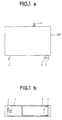
- Fig. 1a is a top plan view illustrating a telephone adaptor not carrying a portable cordless telephone.
- Fig. 1b is a side elevation illustrating a telephone adaptor not carrying a portable cordless telephone.
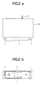
- Fig. 2a is a top plan view illustrating a telephone adaptor carrying a portable cordless telephone.
- Fig. 2b is a side elevation illustrating a telephone adaptor carrying a portable cordless telephone.
- Fig. 3 is a top plan view illustrating a telephone adaptor carrying a portable cordless telephone, with the telephone being gradually projected until it arrives at its maximum outwardly projected position.
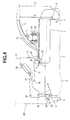
- Fig. 4 is an explanatory view illustrating a mechanism of the present invention for attaching and detaching a portable cordless telephone in a motor vehicle, with the telephone positioned at its received and locked position.
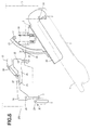
- Fig. 5 is an explanatory view illustrating a mechanism of Fig. 4, with the portable cordless telephone positioned at one of its outwardly projected positions.
- Fig. 6 is an explanatory view illustrating a mechanism of Fig. 4, with the portable cordless telephone positioned at its maximum outwardly projected position.
- Fig. 7 is an explanatory view illustrating a mechanism of Fig. 4, with the portable cordless telephone returned back to its received and locked position.
- Fig. 8 is an explanatory view illustrating a conventional mechanism for attaching and detaching a portable cordless telephone in a motor vehicle.
- Fig. 9 is an explanatory view illustrating another conventional mechanism for attaching and detaching a portable cordless telephone in a motor vehicle.
- Fig. 1a is a top plan view of a telephone adaptor 200 carrying a mechanism of the present invention for attaching and detaching a portable cordless telephone in a motor vehicle.
- Fig. 1b is an elevational view of the telephone adaptor 200 shown in Fig. 1a.
- a mechanism of the present invention has a holder 1 which is so provided that it is pivotable in a horizontal plane.
- the holder 1 has a connector 2 which serves to attach or detach a portable cordless telephone (not shown) by its engagement with a connector (not shown) provided on the bottom of the telephone.
- Reference numeral 3 represents a hook which is provided on the other side on the adaptor 200 far away from the connector 2. Such a hook 3 is used to fix a portable cordless telephone (not shown) in a predetermined position on the telephone adaptor 200 after the connector on the telephone bottom has become engaged with the connector 2. On the other hand, the hook 3 may be released from the the telephone by pushing a release button 4.
- Figs. 2a and 2b together illustrate a condition where a portable cordless telephone 5 has been received in a predetermined position on the telephone adaptor 200.
- the telephone 5 may be connected to a power source and/or other instrument such as a remote controller by way of a cord 6.
- a liquid crystal display panel 7 is provided on the surface of the portable cordless telephone 5. With the use of the liquid crystal display panel 7, it is possible to display a signal when a phone call is being made to the telephone 5, or even display a telephone number which is to be used to make a phone call to a person far away from the motor vehicle.
- the display panel 7 is constructed into a touch-panel, it is possible to perform radio or television channel selection on the display panel 7 by selectively pushing buttons thereon with the use of a remote controller (not shown).
- a speaker of the portable cordless telephone 5 can be used as a car speaker in a vehicle room. Therefore, both the driver and passenger(s) can hear a message from a person making a phone call to this telephone without having to take the telephone 5 from the adaptor 200.
- the holder 1 in engagement with the portable cordless telephone 5 may be caused to pivot so as to project from the telephone adaptor 200 together with the telephone 5.
- the holder 1 and the telephone 5 After the holder 1 and the telephone 5 have been in a slightly projected position 9 as shown in Fig. 3, through a certain hand operation it can continue to pivot together with the telephone 5 in the same direction until they reach a maximum outwardly projected position 10.
- the portable cordless telephone 5 may be detached from the telephone adaptor 200 by separating at the connector 2, so that a car driver can exactly prevent the portable cordless telephone 5 from bumping into surrounding equipments such as a dashboard 8 and a box portion 11.
- Fig. 4 shows a condition where a portable cordless telephone 5 is mounted on the telephone adaptor 200.
- the portable cordless telephone 5 is connected with the connector 2 so as to be received in a predetermined position on the adaptor 200.
- the holder 1 is in the form of a plate produced by punching and bending a metal plate.
- the holder 1 is pivotably supported on a pivoting shaft 14 which is provided on a stationary chassis 13.
- a pivotable arc-shaped pivoting gear 15 made of a synthetic resin.
- the pivoting gear 15 has a predetermined length in its arc path which is formed as having a predetermined semi-diameter R with the pivoting shaft 14 being the pivoting center thereof.
- Such a pivoting gear 15 is engaged with a friction gear 17 which is rotatably provided on the stationary chassis 13.
- the friction gear 17 produces a predetermined friction resistance including a static friction force and a dynamic friction force, such that when the holder 1 is in its standstill position, the holder 1 may be exactly held in position by virtue of the static friction force.
- the pivoting movement of the pivoting gear 15 will be desirably controlled by virtue of the dynamic friction force.
- a stopper 16 Integrally formed on the back surface of the holder 1 is a stopper 16 provided to stop a further pivoting movement of the holder 1 upon the arrival of the holder 1 at its maximum outwardly projected position.
- the stopper 16 is provided in a position corresponding to the arc portion of the pivoting gear 15.
- pivoting gear 15, the friction gear 17 and the stopper 16 together form a pivoting lever device for the mechanism of the present invention.
- a cap member 18 made of a synthetic resin enclosing a compressible spring 19.
- the cap member 18 and the compressible spring 19 together form a pressing means enabling the holder 1 together with the portable cordless telephone 5 to pivot towards their outwardly projected positions, which will be described in more detail later.
- the holder 1 is formed with a notch hole 20 at one end thereof. Close to the hole of the holder 1 there is provided an arm member 21 having a hook 23. The hook 23 is so formed on the arm member 21 that it can easily engage into the notch hole 20.
- Such an arm member 21 is pivotably supported on a pivotal shaft 22 provided on the stationary chassis 13. Since one end of the arm member 21 is flexibly dragged by a spring 24 at one end thereof (the other end of the spring is fixed on the stationary chassis 13), the hook 23 is caused to constantly draw the holder 1 in the direction shown by an arrow A.
- one portion of the arm member 21 is a lever 25 which is formed so as to engage with a lever 27 of another arm member 26.
- the arm member 26 is formed in the same manner using the same material as the arm member 21.
- the arm member 26 is pivotably supported on a pivoting shaft 28 provided on the stationary chassis 13.
- the arm member 26 is also formed with a hook 3, so that when the lever 25 of the arm member 21 is caused to push the lever 27 of the arm member 26 by virtue of a dragging force of the spring 24, the hook 3 of the arm member 26 will exert a pressing force against the portable cordless telephone 5 in a direction shown by an arrow B. In this way, the hook 3 of the arm member 26 will engage into the a groove formed on the side wall of the telephone 5, therefore the portable cordless telephone 5 may be exactly held in its predetermined position on the telephone adaptor 200.
- the arm member 26 is provided with a pin 29 disposed in a vertical position in a vehicle room, such that the side wall of the pin 29 may engage with an inclined surface 30 of the release button 4.
- the portable cordless telephone 5 When the portable cordless telephone 5 is positioned at its attachment position on the telephone adaptor 200 as illustrated in Fig. 4, the telephone 5 is exactly stopped by the hook 3, so that any possible undesired movement of the telephone 5 during the running of a motor vehicle may be prevented.
- the hook 3 and the release button 4 together form a lock/unlock means for locking/unlocking the portable cordless telephone 5 and the holder 1 on the mechanism of the present invention.
- the release button 4 When the portable cordless telephone 5 is to be taken from the telephone adaptor 200, the release button 4 is pushed in a direction shown by an arrow C (Fig. 7). Thus, the side wall of the pin 29 is caused to slide over the inclined surface of the release button 4, this cause the arm 26 to pivot in a direction shown by an arrow D. In this way, the hook 3 of the arm member 26 will be released from the telephone 5.
- the lever 27 since the lever 27 is caused to pivot to press the lever 25 in a direction opposite to the direction C, the arm 21 is forced to pivot in a direction shown by an arrow E (Fig. 7), against an spring force of the spring 24. As a result, the hook 23 is released from the notch hole 20 of the holder 1.
- the compressed state of the spring 19 is also released, so that the spring 19 will press the holder 1 through the cap member 18 by virtue of its restoring force.
- the holder 1 together with the telephone 5 are pressed in a direction F shown by an arrow F (Fig. 5), until they arrive at one projected position as shown in Fig. 5.
- the pivoting gear 15 secured on the holder 1 will cause the friction gear 17 to rotate.
- the restoring force of the spring 19 is controlled, so that the holder 1 is enabled to pivot smoothly to a predetermined projected position in a controlled constant speed. After arriving at the predetermined projected position, the holder 1 will be kept standstill with the effect of the static friction force of the small gear 17.
- the telephone 5 may be easily taken from the telephone adaptor 200 simply by pushing the release button 4 and separating the telephone 5 from the connector 2, avoiding any possibility of damaging the surrounding equipments in a vehicle room.
- Fig. 5 illustrates a condition where the holder 1 together with the telephone 5 have been pivoted to project from the telephone adaptor 200. After the holder 1 together with the telephone 5 are caused to pivot still further in a direction shown by an arrow F (Fig. 5), both of them will arrive at their maximum outwardly projected positions.
- Fig. 6 illustrates a condition where the holder 1 together with the telephone 5 have arrived at their maximum outwardly projected positions.
- the stopper 16 will engage with a portion 31 on the chassis 13, so as to stop a further pivoting movement of the holder 1 upon the arrival of the holder 1 at its maximum outwardly projected position.
- the pivoting gear 15 secured on the holder 1 will cause the friction gear 17 to rotate.
- the restoring force of the spring 19 is controlled, so that the holder 1 is enabled to pivot smoothly to a predetermined maximum projected position in a controlled constant speed. In this way, the holder 1 and the telephone 5 may be stopped and kept still at any desired position between the position shown in Fig. 5 and the position shown in Fig. 6, with the effect of the static friction force of the friction gear 17.
- the telephone 5 When the portable cordless telephone 5 is to be returned back to the telephone adaptor 200, the telephone 5 shall at first be connected to the connector 2 of the holder 1 which has been kept still at one of its projected positions, with the effect of the static friction force of the small gear 17.
- the holder 1 together with the telephone 5 will be changed from a condition shown in Fig. 6 back to a condition shown in Fig. 4, so that the telephone 4 may be received into the predetermined attachment position in the telephone adaptor 200.
- the hook 23 of the arm member 21 will be pressed by the holder 1, so that the arm member 21 is forced to pivot in a direction E.
- the arm member 26 and the hook 3 will pivot in a direction D, so that the portable car telephone 5 will be received into its attachment position on the telephone adaptor 200. Then, the hook 3 of the arm member 26 will move in a direction opposite to the direction D so as to enter a notch of the telephone 5 in order that the telephone 5 may be exactly held in its attachment position on the telephone adaptor 200. Meanwhile, the release button 4 will be changed in its state back to the position of Fig. 4.
- the telephone when the portable car telephone is to be attached back to the telephone adaptor, the telephone may be at first be connected to the holder. Then, the holder together with the telephone may be received into the telephone adaptor. With the use of lock/unlock means, the telephone will be exactly fixed in a predetermined attachment position on the telephone adaptor.
- a cordless telephone may be easily attached to and detached from a telephone detector with only very simple operation, thereby avoiding any possible damages to the surrounding elements in a vehicle room, which otherwise will be caused by a possible collision of the portable cordless telephone with the surrounding elements.
Landscapes
- Engineering & Computer Science (AREA)
- Mechanical Engineering (AREA)
- Fittings On The Vehicle Exterior For Carrying Loads, And Devices For Holding Or Mounting Articles (AREA)
- Telephone Set Structure (AREA)
Applications Claiming Priority (3)
| Application Number | Priority Date | Filing Date | Title |
|---|---|---|---|
| JP14792296A JP3571851B2 (ja) | 1996-05-17 | 1996-05-17 | 車載用携帯電話機の取付機構 |
| JP147922/96 | 1996-05-17 | ||
| JP14792296 | 1996-05-17 |
Publications (2)
| Publication Number | Publication Date |
|---|---|
| EP0807552A1 true EP0807552A1 (fr) | 1997-11-19 |
| EP0807552B1 EP0807552B1 (fr) | 2001-10-24 |
Family
ID=15441132
Family Applications (1)
| Application Number | Title | Priority Date | Filing Date |
|---|---|---|---|
| EP97107826A Expired - Lifetime EP0807552B1 (fr) | 1996-05-17 | 1997-05-13 | Mécanisme pour fixer et détacher un téléphone portatif sans fil dans un véhicule |
Country Status (4)
| Country | Link |
|---|---|
| US (1) | US5896564A (fr) |
| EP (1) | EP0807552B1 (fr) |
| JP (1) | JP3571851B2 (fr) |
| DE (1) | DE69707554T2 (fr) |
Cited By (2)
| Publication number | Priority date | Publication date | Assignee | Title |
|---|---|---|---|---|
| WO2004069599A1 (fr) * | 2003-02-06 | 2004-08-19 | Scania Cv Ab (Publ) | Module d'installation |
| WO2009112532A1 (fr) * | 2008-03-13 | 2009-09-17 | Leopold Kostal Gmbh & Co. Kg | Porte-appareil pour intégration dans un véhicule automobile |
Families Citing this family (12)
| Publication number | Priority date | Publication date | Assignee | Title |
|---|---|---|---|---|
| JP3750025B2 (ja) * | 1995-06-23 | 2006-03-01 | パイケル,アンドレーアス | 送話口及び/又は受話口を有する送受器を備えた電話機 |
| EP0808256A1 (fr) * | 1996-01-05 | 1997-11-26 | Andreas Peiker | Combine telephonique particulierement destine a etre utilise dans un vehicule |
| DE19652715C2 (de) * | 1996-12-18 | 1998-10-01 | Daimler Benz Ag | Haltevorrichtung für das Bedienelement eines Telefons oder Mobiltelefons |
| US6339699B1 (en) * | 1997-09-24 | 2002-01-15 | Harness System Technologies Research, Ltd. | Phone holder |
| US7072689B1 (en) * | 2000-06-05 | 2006-07-04 | Qualcomm, Inc. | Lock and release mechanism for a wireless device |
| JP4705258B2 (ja) * | 2001-03-27 | 2011-06-22 | クラリオン株式会社 | 車載用操作装置 |
| DE10120109C1 (de) * | 2001-04-25 | 2002-06-27 | Harman Becker Automotive Sys | Gehäuse |
| KR100464099B1 (ko) * | 2001-10-09 | 2005-01-03 | 삼성전자주식회사 | 이동기기를 위한 차량용 거치대 |
| US7798682B1 (en) * | 2006-06-08 | 2010-09-21 | Sava Cvek | Personal illumination control systems and devices |
| US8403401B2 (en) * | 2009-08-24 | 2013-03-26 | Daimler Trucks North America Llc | Adjustable air-deflecting panel for a vehicle |
| DE102013019175A1 (de) * | 2013-11-18 | 2015-05-21 | Bayerische Motoren Werke Aktiengesellschaft | Mobiltelefonintegrationssystem |
| CN106794805B (zh) * | 2014-08-06 | 2019-06-28 | 上海延锋金桥汽车饰件系统有限公司 | 用于车辆内的移动设备托架 |
Citations (6)
| Publication number | Priority date | Publication date | Assignee | Title |
|---|---|---|---|---|
| DE3714310A1 (de) * | 1987-04-29 | 1988-11-10 | Bayerische Motoren Werke Ag | Telefonanlage fuer ein kraftfahrzeug |
| WO1990007833A1 (fr) * | 1988-12-30 | 1990-07-12 | Saab Automobile Aktiebolag | Unite de transmission destinee a etre installee dans des vehicules |
| DE4034358C1 (en) * | 1990-10-29 | 1992-01-02 | Mercedes-Benz Aktiengesellschaft, 7000 Stuttgart, De | Pivotable holder for car telephone - has earpiece receptacle on coupling member on ends of levers mounted on fixed rotary bearings |
| DE4107996A1 (de) * | 1991-03-13 | 1992-09-17 | Aeg Mobile Communication | Funkgeraeteanordnung |
| EP0585011A1 (fr) * | 1992-08-22 | 1994-03-02 | Nec Corporation | Dispositif de retenue pour appareils portables |
| WO1996016499A1 (fr) * | 1994-11-23 | 1996-05-30 | Nokia Mobile Phones Ltd. | Support pour telephone mobile ou autre dispositif electrique |
Family Cites Families (3)
| Publication number | Priority date | Publication date | Assignee | Title |
|---|---|---|---|---|
| JPH0427244Y2 (fr) * | 1986-08-26 | 1992-06-30 | ||
| US5438685A (en) * | 1993-11-26 | 1995-08-01 | Motorola, Inc. | Vehicular adapter pocket and handle assembly |
| US5787167A (en) * | 1996-09-12 | 1998-07-28 | Prince Corporation | Vehicle telephone mounting system |
-
1996
- 1996-05-17 JP JP14792296A patent/JP3571851B2/ja not_active Expired - Fee Related
-
1997
- 1997-05-05 US US08/851,275 patent/US5896564A/en not_active Expired - Fee Related
- 1997-05-13 EP EP97107826A patent/EP0807552B1/fr not_active Expired - Lifetime
- 1997-05-13 DE DE69707554T patent/DE69707554T2/de not_active Expired - Fee Related
Patent Citations (6)
| Publication number | Priority date | Publication date | Assignee | Title |
|---|---|---|---|---|
| DE3714310A1 (de) * | 1987-04-29 | 1988-11-10 | Bayerische Motoren Werke Ag | Telefonanlage fuer ein kraftfahrzeug |
| WO1990007833A1 (fr) * | 1988-12-30 | 1990-07-12 | Saab Automobile Aktiebolag | Unite de transmission destinee a etre installee dans des vehicules |
| DE4034358C1 (en) * | 1990-10-29 | 1992-01-02 | Mercedes-Benz Aktiengesellschaft, 7000 Stuttgart, De | Pivotable holder for car telephone - has earpiece receptacle on coupling member on ends of levers mounted on fixed rotary bearings |
| DE4107996A1 (de) * | 1991-03-13 | 1992-09-17 | Aeg Mobile Communication | Funkgeraeteanordnung |
| EP0585011A1 (fr) * | 1992-08-22 | 1994-03-02 | Nec Corporation | Dispositif de retenue pour appareils portables |
| WO1996016499A1 (fr) * | 1994-11-23 | 1996-05-30 | Nokia Mobile Phones Ltd. | Support pour telephone mobile ou autre dispositif electrique |
Cited By (2)
| Publication number | Priority date | Publication date | Assignee | Title |
|---|---|---|---|---|
| WO2004069599A1 (fr) * | 2003-02-06 | 2004-08-19 | Scania Cv Ab (Publ) | Module d'installation |
| WO2009112532A1 (fr) * | 2008-03-13 | 2009-09-17 | Leopold Kostal Gmbh & Co. Kg | Porte-appareil pour intégration dans un véhicule automobile |
Also Published As
| Publication number | Publication date |
|---|---|
| DE69707554D1 (de) | 2001-11-29 |
| DE69707554T2 (de) | 2002-08-01 |
| EP0807552B1 (fr) | 2001-10-24 |
| JPH09301086A (ja) | 1997-11-25 |
| JP3571851B2 (ja) | 2004-09-29 |
| US5896564A (en) | 1999-04-20 |
Similar Documents
| Publication | Publication Date | Title |
|---|---|---|
| US5896564A (en) | Mechanism for attaching and detaching a portable cordless telephone in a motor vehicle | |
| CN1316809C (zh) | 无线设备支架 | |
| US6208734B1 (en) | Holding device for a communications unit | |
| US5995622A (en) | Holder for a telephone handset, and assembly of a holder and a telephone handset | |
| US5128993A (en) | Telephone dispenser with compact cord guide | |
| EP0899162B1 (fr) | Support de combiné téléphonique | |
| JP3563914B2 (ja) | ホルダ装置 | |
| KR930004066Y1 (ko) | 차량용 영상 표시장치 | |
| GB2293718A (en) | Portable telephone set holder | |
| US7756552B2 (en) | Holding device for a cellular phone | |
| US7280656B2 (en) | Holder for an electronic device | |
| US20040132343A1 (en) | Adapter for a telephone holder of a hands-free device | |
| EP1452395B1 (fr) | Equipement électronique avec panneau de commande détachable | |
| JPH04125951U (ja) | 電子部品操作装置 | |
| JP3415691B2 (ja) | 車載用電子機器の取付装置 | |
| US4037063A (en) | Microphone holder assembly | |
| US6041121A (en) | Handset access mechanism and method | |
| JPS5934200Y2 (ja) | 自動車電話機 | |
| JPS5919478Y2 (ja) | 無線装置 | |
| JPH0720731U (ja) | 携帯無線機用架台 | |
| JPH1051154A (ja) | 押しボタン機構及びロック解除押しボタン機構 | |
| JP3698018B2 (ja) | 車室内用電子機器 | |
| JP2000041094A (ja) | 自動車用携帯電話ホルダーのコネクタ接続確認装置 | |
| JPH10324197A (ja) | 車載用モニタの取付け構造 | |
| JP2823639B2 (ja) | 車載無線装置の可搬筐体構造 |
Legal Events
| Date | Code | Title | Description |
|---|---|---|---|
| PUAI | Public reference made under article 153(3) epc to a published international application that has entered the european phase |
Free format text: ORIGINAL CODE: 0009012 |
|
| AK | Designated contracting states |
Kind code of ref document: A1 Designated state(s): DE FR GB |
|
| 17P | Request for examination filed |
Effective date: 19971212 |
|
| 17Q | First examination report despatched |
Effective date: 19990526 |
|
| GRAG | Despatch of communication of intention to grant |
Free format text: ORIGINAL CODE: EPIDOS AGRA |
|
| GRAG | Despatch of communication of intention to grant |
Free format text: ORIGINAL CODE: EPIDOS AGRA |
|
| GRAG | Despatch of communication of intention to grant |
Free format text: ORIGINAL CODE: EPIDOS AGRA |
|
| GRAH | Despatch of communication of intention to grant a patent |
Free format text: ORIGINAL CODE: EPIDOS IGRA |
|
| GRAH | Despatch of communication of intention to grant a patent |
Free format text: ORIGINAL CODE: EPIDOS IGRA |
|
| GRAA | (expected) grant |
Free format text: ORIGINAL CODE: 0009210 |
|
| AK | Designated contracting states |
Kind code of ref document: B1 Designated state(s): DE FR GB |
|
| REF | Corresponds to: |
Ref document number: 69707554 Country of ref document: DE Date of ref document: 20011129 |
|
| REG | Reference to a national code |
Ref country code: GB Ref legal event code: IF02 |
|
| ET | Fr: translation filed | ||
| REG | Reference to a national code |
Ref country code: GB Ref legal event code: 746 Effective date: 20020315 |
|
| REG | Reference to a national code |
Ref country code: FR Ref legal event code: D6 |
|
| PLBE | No opposition filed within time limit |
Free format text: ORIGINAL CODE: 0009261 |
|
| STAA | Information on the status of an ep patent application or granted ep patent |
Free format text: STATUS: NO OPPOSITION FILED WITHIN TIME LIMIT |
|
| 26N | No opposition filed | ||
| PGFP | Annual fee paid to national office [announced via postgrant information from national office to epo] |
Ref country code: FR Payment date: 20040510 Year of fee payment: 8 |
|
| PGFP | Annual fee paid to national office [announced via postgrant information from national office to epo] |
Ref country code: GB Payment date: 20040512 Year of fee payment: 8 |
|
| PGFP | Annual fee paid to national office [announced via postgrant information from national office to epo] |
Ref country code: DE Payment date: 20040520 Year of fee payment: 8 |
|
| PG25 | Lapsed in a contracting state [announced via postgrant information from national office to epo] |
Ref country code: GB Free format text: LAPSE BECAUSE OF NON-PAYMENT OF DUE FEES Effective date: 20050513 |
|
| PG25 | Lapsed in a contracting state [announced via postgrant information from national office to epo] |
Ref country code: DE Free format text: LAPSE BECAUSE OF NON-PAYMENT OF DUE FEES Effective date: 20051201 |
|
| GBPC | Gb: european patent ceased through non-payment of renewal fee |
Effective date: 20050513 |
|
| PG25 | Lapsed in a contracting state [announced via postgrant information from national office to epo] |
Ref country code: FR Free format text: LAPSE BECAUSE OF NON-PAYMENT OF DUE FEES Effective date: 20060131 |
|
| REG | Reference to a national code |
Ref country code: FR Ref legal event code: ST Effective date: 20060131 |