EP0812961A2 - Défense marine caoutchouteuse - Google Patents
Défense marine caoutchouteuse Download PDFInfo
- Publication number
- EP0812961A2 EP0812961A2 EP97304173A EP97304173A EP0812961A2 EP 0812961 A2 EP0812961 A2 EP 0812961A2 EP 97304173 A EP97304173 A EP 97304173A EP 97304173 A EP97304173 A EP 97304173A EP 0812961 A2 EP0812961 A2 EP 0812961A2
- Authority
- EP
- European Patent Office
- Prior art keywords
- rubber
- buckling
- body portion
- marine fender
- rubber body
- Prior art date
- Legal status (The legal status is an assumption and is not a legal conclusion. Google has not performed a legal analysis and makes no representation as to the accuracy of the status listed.)
- Granted
Links
Images


Classifications
-
- E—FIXED CONSTRUCTIONS
- E02—HYDRAULIC ENGINEERING; FOUNDATIONS; SOIL SHIFTING
- E02B—HYDRAULIC ENGINEERING
- E02B3/00—Engineering works in connection with control or use of streams, rivers, coasts, or other marine sites; Sealings or joints for engineering works in general
- E02B3/20—Equipment for shipping on coasts, in harbours or on other fixed marine structures, e.g. bollards
- E02B3/26—Fenders
-
- F—MECHANICAL ENGINEERING; LIGHTING; HEATING; WEAPONS; BLASTING
- F16—ENGINEERING ELEMENTS AND UNITS; GENERAL MEASURES FOR PRODUCING AND MAINTAINING EFFECTIVE FUNCTIONING OF MACHINES OR INSTALLATIONS; THERMAL INSULATION IN GENERAL
- F16F—SPRINGS; SHOCK-ABSORBERS; MEANS FOR DAMPING VIBRATION
- F16F1/00—Springs
- F16F1/36—Springs made of rubber or other material having high internal friction, e.g. thermoplastic elastomers
- F16F1/42—Springs made of rubber or other material having high internal friction, e.g. thermoplastic elastomers characterised by the mode of stressing
- F16F1/422—Springs made of rubber or other material having high internal friction, e.g. thermoplastic elastomers characterised by the mode of stressing the stressing resulting in flexion of the spring
-
- Y—GENERAL TAGGING OF NEW TECHNOLOGICAL DEVELOPMENTS; GENERAL TAGGING OF CROSS-SECTIONAL TECHNOLOGIES SPANNING OVER SEVERAL SECTIONS OF THE IPC; TECHNICAL SUBJECTS COVERED BY FORMER USPC CROSS-REFERENCE ART COLLECTIONS [XRACs] AND DIGESTS
- Y02—TECHNOLOGIES OR APPLICATIONS FOR MITIGATION OR ADAPTATION AGAINST CLIMATE CHANGE
- Y02A—TECHNOLOGIES FOR ADAPTATION TO CLIMATE CHANGE
- Y02A30/00—Adapting or protecting infrastructure or their operation
- Y02A30/30—Adapting or protecting infrastructure or their operation in transportation, e.g. on roads, waterways or railways
Definitions
- This invention relates to a rubbery marine fender, and more particularly to an improvement of a rubbery buckling-type marine fender such as hollow cylindrical marine fender, V-shaped marine fender or the like absorbing energy in the berthing of a vessel and causing a buckling phenomenon in the compression deformation.
- a rubbery buckling-type marine fender such as hollow cylindrical marine fender, V-shaped marine fender or the like absorbing energy in the berthing of a vessel and causing a buckling phenomenon in the compression deformation.
- a rubbery hollow cylindrical marine fender of a conical trapezoidal form as shown in Fig. 1.
- This marine fender comprises a main cylindrical rubber portion 12, a securing flange portion 13 for a quay wall, a shock receiving portion 14 and iron plates 15, 16 embedded in the portions 13, 14.
- a deflection-reaction force curve absorbing a berthing energy as shown in Fig. 2.
- Fig. 2 after the reaction force increases with the increase of the deflection to arrive at an upper peak (point A), it decreases to arrive at a point C though the deflection increases, and again rapidly increases with further increase of the deflection.
- the actually usable range is a deflection range from the reaction force at the point A to a point B showing the reaction force equal to the point A, in which the absorption energy of the marine fender is represented by an area defined between the deflection-reaction force and an abscissa up to the point B.
- the reaction force is actually decreased to the point C, so that the absorption energy is lost only by a portion S corresponding to an area surrounded with a dotted line A-B and a curve A-C-B.
- the invention is to provide a rubbery marine fender capable of reducing the aforementioned loss of the absorption energy (S) as far as possible.
- the invention is to provide a rubbery marine fender capable of efficiently preventing the falling phenomenon of reaction force produced through the buckling deformation of the main rubber body portion in the marine fender by compression of a rubber buildup portion arranged adjacent or close to an outer buckling point of the main rubber body portion.
- a rubbery marine fender comprising a main rubber body portion having substantially a frustoconical shape in its outer surface and inner surface, a shock receiving rubber portion formed on a base face of the main rubber body portion and a securing rubber flange portion extending from a bottom face of the main rubber body portion along a securing face thereof, in which a rubber buildup portion protruding outward from the outer surface of the main rubber body portion is arranged on the outer surface of the main rubber body portion at either or both regions adjacent or close to a buckling peripheral line thereof.
- a rubber buildup portion protruding inward from the inner surface of the main rubber body portion is arranged on the inner surface of the main rubber body portion at a region adjacent or close to a buckling peripheral line thereof.
- At least outer surface of the main rubber body portion is a curved face of a diameter broadening toward the securing face.
- a disc-shaped or annular rigid plate is embedded in the shock receiving rubber portion and an annular rigid plate is embedded in the securing rubber portion.
- the buckling peripheral line is created on the outer surface of the main rubber body portion by the disc-shaped iron plate embedded in the shock receiving rubber portion.
- the invention is based on knowledges obtained by actually observing the compression deformation of the buckling-type rubbery cylindrical marine fender in detail.
- the deformation proceeds from a left side toward a right side as shown by arrow in Fig. 3, during which the reaction force arrives at a peak (greatest point A) at once and largely falls down before the arrival to the point B.
- the falling of the reaction force between the points A and B in Fig. 2 is caused in the course of the buckling deformation at the buckling peripheral line P on the outer surface of the main rubber body portion (or further with the buckling peripheral line L on the inner surface). That is, the upper and lower outer surfaces of the main rubber body portion do not contact with each other with respect to the buckling peripheral line P at the first and second steps of Fig. 3.
- a rubber buildup portion 9 is arranged on the outer surface of the main rubber body portion at either or both regions adjacent or close to a buckling peripheral line P thereof, whereby contact compression zone is positively increased between the points A and B to increase the reaction force.
- the buckling peripheral line P is always held at a given position by the rubber buildup portion 9 formed on the outer surface of the main rubber body portion.
- the buckling peripheral line P is not frequently specified in the conventional marine fender, so that the position of the buckling peripheral line P scatters every compression even in a lot of products or the same product and hence the scattering of the reaction force is caused.
- the formation of the rubber buildup portion 9 according to the invention solves this drawback of the conventional marine fender and reduces the scattering of reaction force.
- the buckling peripheral line P is positively established by forming the rubber buildup portion 9 on the outer surface of the main rubber body portion in the marine fender according to the invention, the position of the buckling peripheral line P is separated apart from the position of the iron plate embedded in the securing rubber portion for quay wall, so that the concentration of stress in the embedded iron plate can be prevented to prevent the peeling between rubber and iron plate and the rubber breakage to thereby improve the durability.
- h 1 a position of the buckling peripheral line P
- H is a height of the marine fender as measured from a base line thereof.
- the height of the rubber buildup portion 9 is properly selected in accordance with the size of the marine fender, the length of the rubber buildup portion, the thickness of the main rubber body portion and the like.
- FIG. 5 a first embodiment of the rubbery cylindrical marine fender according to the invention.
- This marine fender 1 comprises a main rubber body portion 2 having a frustoconical shape in its outer surface and inner surface, a securing rubber flange portion 3 for fixing to a quay wall or the like, and a shock receiving rubber portion 4 protruding toward a vessel.
- a shock receiving plate (not shown) directly supporting the berthing of the vessel.
- an annular iron plate 5 is embedded in the shock receiving rubber portion 4 for the reinforcement thereof and internal thread (not shown) are formed therein for fixing the shock receiving plate.
- an annular iron plate 7 is embedded in the securing rubber flange portion 3 for the reinforcement thereof and a bolt hole 8 is formed therein for fixing to the quay wall or the like through a bolt or anchor (not shown).
- the buckling peripheral line P formed on the outer surface of the main rubber body portion 2 is a buckling part when a berthing load or the like is applied to the shock receiving plate.
- a position h 1 of the buckling peripheral line P is about 0.8H as measured from the securing rubber flange portion 3.
- the main rubber body portion 2 is largely bulged outward by starting from the buckling peripheral line P to cause the buckling, whereby the berthing load is absorbed.
- the buckling peripheral line P is created at two positions upward and downward.
- the marine fender 1 according to the invention is less in the falling of the reaction force between the points A and B in the deflection-reaction force curve as shown in Fig. 2 because the reaction force changes in a substantially horizontal direction (broken lines), so that the increase of the reaction force can be attained.
- the rubber buildup portion 9 is formed on one-side of the upper buckling peripheral line P in the illustrated embodiment, the rubber buildup portion may also be formed on a region(s) adjacent to the lower. buckling peripheral line P. According to circumstances, rubber buildup portions 9 may be formed on both regions sandwiching each of these buckling peripheral lines P.
- the buckling peripheral line P Since the buckling peripheral line P is formed inward from positions embedding the reinforcing iron plates 5, 7, the buckling peripheral line P acts together with the buckling peripheral line L formed on the inner surface of the main rubber body portion 2 to start the buckling of the marine fender 1 and develops the prevention of the peel or rubber breakage at the contact face between the embedded iron plate 5, 7 and rubber.
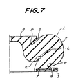
- a second embodiment of the cylindrical marine fender 1 in which numerals 1-9 and symbol P and the like have the same meanings as in the first embodiment.
- the buckling peripheral line L is also formed on the inner surface of the main rubber body portion 2
- a rubber buildup portion 10 is formed on one-side adjacent to the buckling peripheral line L likewise the case of forming the rubber buildup portion 9.
- a position h 2 of the buckling peripheral line L is 1/3H and a length l 2 of the rubber buildup portion 10 is 0.5H.
- the space in the vicinity of the buckling peripheral line P is positively removed by the rubber buildup portion in the buckling and hence there is caused no lowering of the reaction force in the deflection-reaction force curve, so that the invention provides a marine fender having improved absorption performance against berthing shock.
Landscapes
- Engineering & Computer Science (AREA)
- General Engineering & Computer Science (AREA)
- Ocean & Marine Engineering (AREA)
- Mechanical Engineering (AREA)
- Environmental & Geological Engineering (AREA)
- Civil Engineering (AREA)
- Structural Engineering (AREA)
- Health & Medical Sciences (AREA)
- Child & Adolescent Psychology (AREA)
- Vibration Dampers (AREA)
- Bridges Or Land Bridges (AREA)
Applications Claiming Priority (2)
| Application Number | Priority Date | Filing Date | Title |
|---|---|---|---|
| JP8174145A JPH101927A (ja) | 1996-06-13 | 1996-06-13 | ゴム製防舷材 |
| JP174145/96 | 1996-06-13 |
Publications (3)
| Publication Number | Publication Date |
|---|---|
| EP0812961A2 true EP0812961A2 (fr) | 1997-12-17 |
| EP0812961A3 EP0812961A3 (fr) | 1998-05-20 |
| EP0812961B1 EP0812961B1 (fr) | 2007-08-01 |
Family
ID=15973466
Family Applications (1)
| Application Number | Title | Priority Date | Filing Date |
|---|---|---|---|
| EP97304173A Expired - Lifetime EP0812961B1 (fr) | 1996-06-13 | 1997-06-13 | Défense marine caoutchouteuse |
Country Status (6)
| Country | Link |
|---|---|
| US (1) | US5975000A (fr) |
| EP (1) | EP0812961B1 (fr) |
| JP (1) | JPH101927A (fr) |
| AU (1) | AU684030B1 (fr) |
| DE (1) | DE69737961T2 (fr) |
| ES (1) | ES2290961T3 (fr) |
Cited By (5)
| Publication number | Priority date | Publication date | Assignee | Title |
|---|---|---|---|---|
| WO2003029565A1 (fr) | 2001-10-01 | 2003-04-10 | Metso Minerals (Trelleborg) Ab | Defense |
| US6572307B2 (en) | 1999-12-20 | 2003-06-03 | Sumitomo Rubber Industries, Ltd. | Fender with step and/or projection |
| US6701860B2 (en) | 2001-10-01 | 2004-03-09 | Metso Minerals (Trelleborg) Ab | Fender |
| AU2005200291B2 (en) * | 1999-12-20 | 2006-09-28 | Sumitomo Rubber Industries, Ltd. | Fender |
| EP3591254A1 (fr) * | 2018-07-05 | 2020-01-08 | The Boeing Company | Ressort de compression élastomère avec fonction de réglage de charge et procédé de réglage associé |
Families Citing this family (10)
| Publication number | Priority date | Publication date | Assignee | Title |
|---|---|---|---|---|
| JP3486894B2 (ja) * | 1998-12-24 | 2004-01-13 | 船井電機株式会社 | 防振支持装置 |
| SE520131C2 (sv) * | 2000-04-25 | 2003-05-27 | Sumitomo Rubber Ind | Fender samt framställning av densamma |
| US6604735B2 (en) * | 2000-12-22 | 2003-08-12 | Lockheed Martin Corporation | Elastomer variants |
| US7401824B2 (en) * | 2005-04-29 | 2008-07-22 | Romeo-Rim, Inc. | Reinforced energy absorbing bumper |
| KR100861003B1 (ko) | 2007-11-29 | 2008-09-30 | (주)동양기업 | 스풀타입의 방현재를 제조하는 방법과 그 장치 |
| JP5700629B2 (ja) * | 2010-09-28 | 2015-04-15 | 株式会社ブリヂストン | 防舷材 |
| KR101080211B1 (ko) | 2011-08-04 | 2011-11-07 | (주)화승케미칼 | 콘 타입 방현재와 이의 제조방법 |
| CN104355261A (zh) * | 2014-10-23 | 2015-02-18 | 上海市东方海事工程技术有限公司 | 自润滑蜗轮蜗杆丝杆升降机 |
| US12466536B2 (en) * | 2022-02-02 | 2025-11-11 | Textron Innovations Inc. | Aircraft stair system using bumper arrangement |
| KR200497333Y1 (ko) * | 2023-07-10 | 2023-10-12 | (주)에이치에스씨 | 콘타입 방현재 |
Family Cites Families (8)
| Publication number | Priority date | Publication date | Assignee | Title |
|---|---|---|---|---|
| GB1266106A (fr) * | 1970-09-04 | 1972-03-08 | ||
| DE2104212A1 (de) * | 1971-01-29 | 1972-08-03 | Clouth Gummiwerke Ag | Puffer oder Fender |
| FR2320391A1 (fr) * | 1975-08-07 | 1977-03-04 | Bridgestone Tire Co Ltd | Defense marine creuse en elastomere caoutchouteux |
| JPS58168706A (ja) * | 1982-03-31 | 1983-10-05 | Bridgestone Corp | 防舷材 |
| JPS6043515A (ja) * | 1983-08-22 | 1985-03-08 | Bridgestone Corp | 防舷材 |
| JPS6055111A (ja) * | 1983-09-05 | 1985-03-30 | Bridgestone Corp | 防舷材 |
| AU664794B2 (en) * | 1993-03-29 | 1995-11-30 | Bridgestone Corporation | Marine fenders |
| KR100257718B1 (ko) * | 1995-06-26 | 2000-06-01 | 이상춘 | 방현재 |
-
1996
- 1996-06-13 JP JP8174145A patent/JPH101927A/ja active Pending
-
1997
- 1997-06-10 US US08/872,172 patent/US5975000A/en not_active Expired - Lifetime
- 1997-06-11 AU AU24806/97A patent/AU684030B1/en not_active Expired
- 1997-06-13 EP EP97304173A patent/EP0812961B1/fr not_active Expired - Lifetime
- 1997-06-13 ES ES97304173T patent/ES2290961T3/es not_active Expired - Lifetime
- 1997-06-13 DE DE69737961T patent/DE69737961T2/de not_active Expired - Lifetime
Cited By (9)
| Publication number | Priority date | Publication date | Assignee | Title |
|---|---|---|---|---|
| US6572307B2 (en) | 1999-12-20 | 2003-06-03 | Sumitomo Rubber Industries, Ltd. | Fender with step and/or projection |
| SG96592A1 (en) * | 1999-12-20 | 2003-06-16 | Sumitomo Rubber Ind | Fender |
| AU2005200291B2 (en) * | 1999-12-20 | 2006-09-28 | Sumitomo Rubber Industries, Ltd. | Fender |
| WO2003029565A1 (fr) | 2001-10-01 | 2003-04-10 | Metso Minerals (Trelleborg) Ab | Defense |
| US6701860B2 (en) | 2001-10-01 | 2004-03-09 | Metso Minerals (Trelleborg) Ab | Fender |
| AU2002341473B2 (en) * | 2001-10-01 | 2008-01-03 | Trelleborg Industri Ab | Fender |
| EP3591254A1 (fr) * | 2018-07-05 | 2020-01-08 | The Boeing Company | Ressort de compression élastomère avec fonction de réglage de charge et procédé de réglage associé |
| US10962073B2 (en) | 2018-07-05 | 2021-03-30 | The Boeing Company | Elastomeric compression spring with load tuning feature and associated method of tuning |
| US11754136B2 (en) | 2018-07-05 | 2023-09-12 | The Boeing Company | Elastomeric compression spring with load tuning feature and associated method of tuning |
Also Published As
| Publication number | Publication date |
|---|---|
| EP0812961B1 (fr) | 2007-08-01 |
| US5975000A (en) | 1999-11-02 |
| DE69737961T2 (de) | 2008-04-17 |
| EP0812961A3 (fr) | 1998-05-20 |
| AU684030B1 (en) | 1997-11-27 |
| ES2290961T3 (es) | 2008-02-16 |
| DE69737961D1 (de) | 2007-09-13 |
| JPH101927A (ja) | 1998-01-06 |
Similar Documents
| Publication | Publication Date | Title |
|---|---|---|
| US5975000A (en) | Rubbery marine fenders | |
| EP0622495B1 (fr) | Défense marine | |
| US4277055A (en) | Cushioning fender | |
| WO1995033917A1 (fr) | Rondelle utilisable dans les mines | |
| JP2000204723A (ja) | 屋根ふきプレ―ト | |
| US4518282A (en) | Mine roof bearing plate with embossed area having conical and cylindrical sections | |
| US4515502A (en) | Marine fenders | |
| US4601611A (en) | Marine fender | |
| US5054414A (en) | Hollow rubber fender | |
| US5791828A (en) | Plate for use in support of a mine roof | |
| JP3706250B2 (ja) | 柱脚用ベースプレート | |
| JPH07229129A (ja) | ゴム製筒型防舷材 | |
| EP0125754B1 (fr) | Amortisseur d'accostage marin | |
| EP0102210B1 (fr) | Défense marine | |
| JP3745752B2 (ja) | 鋼管柱構造 | |
| JPH0649826A (ja) | 防舷材 | |
| JPH0874225A (ja) | 防舷材 | |
| JPS6319279Y2 (fr) | ||
| JP2003253653A (ja) | 防舷材 | |
| AU682119B2 (en) | Washer for use in mining | |
| JPH041129B2 (fr) | ||
| JP2000168680A (ja) | 浮体用緩衝材 | |
| JPH0813450A (ja) | 防舷材 | |
| JP2001348887A (ja) | 柱杭接合構造 | |
| JPH06280237A (ja) | 防舷材 |
Legal Events
| Date | Code | Title | Description |
|---|---|---|---|
| PUAI | Public reference made under article 153(3) epc to a published international application that has entered the european phase |
Free format text: ORIGINAL CODE: 0009012 |
|
| AK | Designated contracting states |
Kind code of ref document: A2 Designated state(s): DE ES GB NL SE |
|
| PUAL | Search report despatched |
Free format text: ORIGINAL CODE: 0009013 |
|
| AK | Designated contracting states |
Kind code of ref document: A3 Designated state(s): AT BE CH DE DK ES FI FR GB GR IE IT LI LU MC NL PT SE |
|
| 17P | Request for examination filed |
Effective date: 19980930 |
|
| AKX | Designation fees paid |
Free format text: DE ES GB NL SE |
|
| RBV | Designated contracting states (corrected) |
Designated state(s): DE ES GB NL SE |
|
| 17Q | First examination report despatched |
Effective date: 20030506 |
|
| GRAP | Despatch of communication of intention to grant a patent |
Free format text: ORIGINAL CODE: EPIDOSNIGR1 |
|
| GRAS | Grant fee paid |
Free format text: ORIGINAL CODE: EPIDOSNIGR3 |
|
| GRAA | (expected) grant |
Free format text: ORIGINAL CODE: 0009210 |
|
| AK | Designated contracting states |
Kind code of ref document: B1 Designated state(s): DE ES GB NL SE |
|
| REG | Reference to a national code |
Ref country code: GB Ref legal event code: FG4D |
|
| REF | Corresponds to: |
Ref document number: 69737961 Country of ref document: DE Date of ref document: 20070913 Kind code of ref document: P |
|
| REG | Reference to a national code |
Ref country code: SE Ref legal event code: TRGR |
|
| REG | Reference to a national code |
Ref country code: ES Ref legal event code: FG2A Ref document number: 2290961 Country of ref document: ES Kind code of ref document: T3 |
|
| PLBE | No opposition filed within time limit |
Free format text: ORIGINAL CODE: 0009261 |
|
| STAA | Information on the status of an ep patent application or granted ep patent |
Free format text: STATUS: NO OPPOSITION FILED WITHIN TIME LIMIT |
|
| 26N | No opposition filed |
Effective date: 20080506 |
|
| REG | Reference to a national code |
Ref country code: DE Ref legal event code: R081 Ref document number: 69737961 Country of ref document: DE Owner name: BRIDGESTONE CORPORATION, JP Free format text: FORMER OWNER: BRIDGESTONE CORP., TOKIO/TOKYO, JP Effective date: 20140828 |
|
| PGFP | Annual fee paid to national office [announced via postgrant information from national office to epo] |
Ref country code: ES Payment date: 20160614 Year of fee payment: 20 Ref country code: GB Payment date: 20160621 Year of fee payment: 20 Ref country code: DE Payment date: 20160621 Year of fee payment: 20 |
|
| PGFP | Annual fee paid to national office [announced via postgrant information from national office to epo] |
Ref country code: NL Payment date: 20160620 Year of fee payment: 20 Ref country code: SE Payment date: 20160620 Year of fee payment: 20 |
|
| REG | Reference to a national code |
Ref country code: DE Ref legal event code: R071 Ref document number: 69737961 Country of ref document: DE |
|
| REG | Reference to a national code |
Ref country code: NL Ref legal event code: MK Effective date: 20170612 |
|
| REG | Reference to a national code |
Ref country code: GB Ref legal event code: PE20 Expiry date: 20170612 |
|
| PG25 | Lapsed in a contracting state [announced via postgrant information from national office to epo] |
Ref country code: GB Free format text: LAPSE BECAUSE OF EXPIRATION OF PROTECTION Effective date: 20170612 |
|
| REG | Reference to a national code |
Ref country code: SE Ref legal event code: EUG |
|
| REG | Reference to a national code |
Ref country code: ES Ref legal event code: FD2A Effective date: 20170926 |
|
| PG25 | Lapsed in a contracting state [announced via postgrant information from national office to epo] |
Ref country code: ES Free format text: LAPSE BECAUSE OF EXPIRATION OF PROTECTION Effective date: 20170614 |