EP0817338A2 - Appareil laser - Google Patents
Appareil laser Download PDFInfo
- Publication number
- EP0817338A2 EP0817338A2 EP97110646A EP97110646A EP0817338A2 EP 0817338 A2 EP0817338 A2 EP 0817338A2 EP 97110646 A EP97110646 A EP 97110646A EP 97110646 A EP97110646 A EP 97110646A EP 0817338 A2 EP0817338 A2 EP 0817338A2
- Authority
- EP
- European Patent Office
- Prior art keywords
- laser light
- laser
- oscillation apparatus
- coolant
- laser oscillation
- Prior art date
- Legal status (The legal status is an assumption and is not a legal conclusion. Google has not performed a legal analysis and makes no representation as to the accuracy of the status listed.)
- Granted
Links
Images





Classifications
-
- H—ELECTRICITY
- H01—ELECTRIC ELEMENTS
- H01S—DEVICES USING THE PROCESS OF LIGHT AMPLIFICATION BY STIMULATED EMISSION OF RADIATION [LASER] TO AMPLIFY OR GENERATE LIGHT; DEVICES USING STIMULATED EMISSION OF ELECTROMAGNETIC RADIATION IN WAVE RANGES OTHER THAN OPTICAL
- H01S3/00—Lasers, i.e. devices using stimulated emission of electromagnetic radiation in the infrared, visible or ultraviolet wave range
- H01S3/09—Processes or apparatus for excitation, e.g. pumping
- H01S3/097—Processes or apparatus for excitation, e.g. pumping by gas discharge of a gas laser
-
- B—PERFORMING OPERATIONS; TRANSPORTING
- B23—MACHINE TOOLS; METAL-WORKING NOT OTHERWISE PROVIDED FOR
- B23K—SOLDERING OR UNSOLDERING; WELDING; CLADDING OR PLATING BY SOLDERING OR WELDING; CUTTING BY APPLYING HEAT LOCALLY, e.g. FLAME CUTTING; WORKING BY LASER BEAM
- B23K26/00—Working by laser beam, e.g. welding, cutting or boring
- B23K26/70—Auxiliary operations or equipment
- B23K26/702—Auxiliary equipment
- B23K26/704—Beam dispersers, e.g. beam wells
-
- H—ELECTRICITY
- H01—ELECTRIC ELEMENTS
- H01S—DEVICES USING THE PROCESS OF LIGHT AMPLIFICATION BY STIMULATED EMISSION OF RADIATION [LASER] TO AMPLIFY OR GENERATE LIGHT; DEVICES USING STIMULATED EMISSION OF ELECTROMAGNETIC RADIATION IN WAVE RANGES OTHER THAN OPTICAL
- H01S3/00—Lasers, i.e. devices using stimulated emission of electromagnetic radiation in the infrared, visible or ultraviolet wave range
- H01S3/005—Optical devices external to the laser cavity, specially adapted for lasers, e.g. for homogenisation of the beam or for manipulating laser pulses, e.g. pulse shaping
-
- H—ELECTRICITY
- H01—ELECTRIC ELEMENTS
- H01S—DEVICES USING THE PROCESS OF LIGHT AMPLIFICATION BY STIMULATED EMISSION OF RADIATION [LASER] TO AMPLIFY OR GENERATE LIGHT; DEVICES USING STIMULATED EMISSION OF ELECTROMAGNETIC RADIATION IN WAVE RANGES OTHER THAN OPTICAL
- H01S3/00—Lasers, i.e. devices using stimulated emission of electromagnetic radiation in the infrared, visible or ultraviolet wave range
- H01S3/02—Constructional details
- H01S3/03—Constructional details of gas laser discharge tubes
-
- H—ELECTRICITY
- H01—ELECTRIC ELEMENTS
- H01S—DEVICES USING THE PROCESS OF LIGHT AMPLIFICATION BY STIMULATED EMISSION OF RADIATION [LASER] TO AMPLIFY OR GENERATE LIGHT; DEVICES USING STIMULATED EMISSION OF ELECTROMAGNETIC RADIATION IN WAVE RANGES OTHER THAN OPTICAL
- H01S3/00—Lasers, i.e. devices using stimulated emission of electromagnetic radiation in the infrared, visible or ultraviolet wave range
- H01S3/02—Constructional details
- H01S3/04—Arrangements for thermal management
- H01S3/0401—Arrangements for thermal management of optical elements being part of laser resonator, e.g. windows, mirrors, lenses
-
- H—ELECTRICITY
- H01—ELECTRIC ELEMENTS
- H01S—DEVICES USING THE PROCESS OF LIGHT AMPLIFICATION BY STIMULATED EMISSION OF RADIATION [LASER] TO AMPLIFY OR GENERATE LIGHT; DEVICES USING STIMULATED EMISSION OF ELECTROMAGNETIC RADIATION IN WAVE RANGES OTHER THAN OPTICAL
- H01S3/00—Lasers, i.e. devices using stimulated emission of electromagnetic radiation in the infrared, visible or ultraviolet wave range
- H01S3/02—Constructional details
- H01S3/04—Arrangements for thermal management
- H01S3/041—Arrangements for thermal management for gas lasers
-
- H—ELECTRICITY
- H01—ELECTRIC ELEMENTS
- H01S—DEVICES USING THE PROCESS OF LIGHT AMPLIFICATION BY STIMULATED EMISSION OF RADIATION [LASER] TO AMPLIFY OR GENERATE LIGHT; DEVICES USING STIMULATED EMISSION OF ELECTROMAGNETIC RADIATION IN WAVE RANGES OTHER THAN OPTICAL
- H01S3/00—Lasers, i.e. devices using stimulated emission of electromagnetic radiation in the infrared, visible or ultraviolet wave range
- H01S3/02—Constructional details
- H01S3/03—Constructional details of gas laser discharge tubes
- H01S3/032—Constructional details of gas laser discharge tubes for confinement of the discharge, e.g. by special features of the discharge constricting tube
- H01S3/0323—Constructional details of gas laser discharge tubes for confinement of the discharge, e.g. by special features of the discharge constricting tube by special features of the discharge constricting tube, e.g. capillary
-
- H—ELECTRICITY
- H01—ELECTRIC ELEMENTS
- H01S—DEVICES USING THE PROCESS OF LIGHT AMPLIFICATION BY STIMULATED EMISSION OF RADIATION [LASER] TO AMPLIFY OR GENERATE LIGHT; DEVICES USING STIMULATED EMISSION OF ELECTROMAGNETIC RADIATION IN WAVE RANGES OTHER THAN OPTICAL
- H01S3/00—Lasers, i.e. devices using stimulated emission of electromagnetic radiation in the infrared, visible or ultraviolet wave range
- H01S3/02—Constructional details
- H01S3/03—Constructional details of gas laser discharge tubes
- H01S3/034—Optical devices within, or forming part of, the tube, e.g. windows, mirrors
-
- H—ELECTRICITY
- H01—ELECTRIC ELEMENTS
- H01S—DEVICES USING THE PROCESS OF LIGHT AMPLIFICATION BY STIMULATED EMISSION OF RADIATION [LASER] TO AMPLIFY OR GENERATE LIGHT; DEVICES USING STIMULATED EMISSION OF ELECTROMAGNETIC RADIATION IN WAVE RANGES OTHER THAN OPTICAL
- H01S3/00—Lasers, i.e. devices using stimulated emission of electromagnetic radiation in the infrared, visible or ultraviolet wave range
- H01S3/02—Constructional details
- H01S3/03—Constructional details of gas laser discharge tubes
- H01S3/036—Means for obtaining or maintaining the desired gas pressure within the tube, e.g. by gettering, replenishing; Means for circulating the gas, e.g. for equalising the pressure within the tube
-
- H—ELECTRICITY
- H01—ELECTRIC ELEMENTS
- H01S—DEVICES USING THE PROCESS OF LIGHT AMPLIFICATION BY STIMULATED EMISSION OF RADIATION [LASER] TO AMPLIFY OR GENERATE LIGHT; DEVICES USING STIMULATED EMISSION OF ELECTROMAGNETIC RADIATION IN WAVE RANGES OTHER THAN OPTICAL
- H01S3/00—Lasers, i.e. devices using stimulated emission of electromagnetic radiation in the infrared, visible or ultraviolet wave range
- H01S3/02—Constructional details
- H01S3/04—Arrangements for thermal management
Definitions
- the present invention relates to a laser oscillation apparatus for generating laser light by oscillation and optical amplification by means of a pair of optical amplification mirrors.
- the present invention relates to a laser oscillation apparatus improved with respect to at least one of a high voltage power source circuit for generating a discharge, resulting in an enhanced freedom in design, a control unit for a cooling mechanism which allows a stable laser output to be achieved in a short period of time after start-up in a cold atmosphere, and a laser light absorption unit for receiving and absorbing laser light and exchanging heat with a coolant.
- Figure 14 is a diagram schematically illustrating a configuration around a laser cavity unit 1100 in a conventional laser oscillation apparatus.
- a laser cavity unit 1100 includes a laser tube 106 , a partially-transmissive reflection mirror 104 , and a total reflection mirror 105 .
- a high voltage is applied from a DC high voltage power source 102 via discharge electrodes 103a and 103b to a gaseous laser medium 101 contained in the laser tube 106 so as to generate a glow discharge.
- a blower 107 and a laser medium cooler 108 are serially connected to the laser tube 106 via laser medium conduits 109a and 109b .
- the laser medium 101 is forcibly circulated by the blower 107 .
- the gaseous laser medium 101 heated by the glow discharge, passes through the laser medium conduit 109b , is cooled by the laser medium cooler 108 , passes through the blower 107 and the laser medium conduit 109a , and then is sent back to a glow discharge space in the laser tube 106 .
- the total reflection mirror 105 is provided at one end of the laser tube 106 , and the partially-transmissive reflection mirror 104 is provided at the other end thereof. Laser light generated by a discharge passes through the partially-transmissive reflection mirror 104 and exits the laser tube 106 .
- the DC high voltage power source 102 is directly connected to the discharge electrodes 103a and 103b via feeder cables 111a and 111b . Furthermore, a cathode of the DC high voltage power source 102 , which is connected to the discharge electrode 103b , is grounded by the grounding conductor 110 .
- a DC high voltage E (V) which corresponds to the supplied voltage level of the DC high voltage power source 102 (with the ground level being the reference level), appears at the discharge electrode 103a .
- V DC high voltage
- the feeder cable 111a must have a sufficient anti-breakdown property so that it can withstand the DC high voltage E (V).
- the need for a feeder cable with such a high anti-breakdown property disadvantageously increases cost for conventional laser oscillation apparatuses.
- Figure 15 is a diagram schematically illustrating an exemplary configuration of a cooling mechanism which can be used by being connected to the laser cavity unit 1100 of the laser oscillation apparatus described above. Elements in Figure 15 which are also shown in Figure 14 are denoted by the same reference numerals and will not be further described.
- optical components such as the partially-transmissive reflection mirror 104 and the total reflection mirror 105 are held by a holder 207 .
- some thermal energy from a discharge may be applied to the holder 207 , and thus, the holder 207 may be deformed by thermal expansion, resulting in deteriorated positional parallel relationship between the partially-transmissive reflection mirror 104 and the total reflection mirror 105 .
- the partially-transmissive reflection mirror 104 and the total reflection mirror 105 may be shifted with respect to each other from the predetermined positional parallel relationship due to contraction of the holder 207 induced by low temperature.
- oil for example, is circulated within the holder 207 by means of a pump 208 to cool the holder 207 .
- a cooling mechanism using oil includes a tank 211 , the pump 208 for supplying the oil into the holder 207 , a cooler 210 for cooling the oil, and a thermistor 209 for detecting the oil temperature.
- a control unit 212 is provided for controlling the operation of the cooler 210 based on the oil temperature detected by the thermistor 209 . After the operation of the laser oscillation apparatus is initiated, the oil is cooled by controlling the operation of the cooler 210 according to a control loop as shown in a dashed line in Figure 15 .
- Figure 16 shows diagrams provided for illustrating problems associated with such a cooling mechanism for optical components in the conventional laser oscillation apparatus.
- the portion (a) of Figure 16 schematically illustrates the change in the temperature of the oil in the cooling mechanism from shutdown to some time after subsequent start-up.
- the temperature indicated therein can be considered as the temperature of the holder 207 , which is cooled by the oil.
- the portion (d) of Figure 16 is a diagram schematically illustrating the change in the laser output of the laser oscillation apparatus after start-up, and the portions (b) and (c) of Figure 16 illustrate the operation timing of the pump 208 and the cooler 210 , respectively, after start-up.
- the temperature of the holder 207 becomes considerably lower than the normal operating point temperature of the laser oscillation apparatus. Accordingly, the oil temperature becomes also low as shown in the portion (a) of Figure 16 . Due to such a considerably low temperature, a great amount of time may be required for warm up of the holder 207 to an operating temperature, which is shown as the oil temperature change in the portion (a) of Figure 16 , after the oscillation apparatus has started its operation at the time shown in the portion (d) of Figure 16 and the pump 208 has accordingly started its operation at the time shown in the portion (b) of Figure 16 .
- the positional parallel relationship between the partially-transmissive reflection mirror 104 and the total reflection mirror 105 is shifted for a while after start-up, during which a stable light amplification (laser oscillation) can not be achieved, resulting in a lowered laser output.
- a great amount of time is required until the laser output becomes stable again at the normal operating level.
- control unit 212 acts to cause the cooler 210 to operate at an appropriate time as shown in the portion (c) of Figure 16 . This allows for a stable operation of the laser oscillation apparatus.
- the laser light absorption unit is provided on the optical path of the generated laser light. Normally, the laser light absorption unit is located so as to block the optical path of the laser light, thereby preventing the laser light generated in the laser cavity unit from exiting the laser oscillation apparatus at any time other than a desired time, thus functioning as a safety apparatus. Then, once it is confirmed that the laser light may exit (e.g., in a manufacturing site, when it is confirmed that the laser light has been aimed to an object to be processed and that there is no obstruction in the intervening path), the laser light absorption unit is shifted aside the optical path of the laser light so that the laser light exits the laser oscillation apparatus.
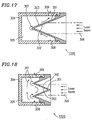
- Figure 17 is a cross-sectional view schematically illustrating a configuration of a conventional laser light absorption unit 1310 .
- a conically-shaped inner cylinder 301 is provided at an opening of an outer cylinder 304 .
- the conically-shaped inner cylinder 301 includes a light-receiving surface 302 and a heat-exchanging surface 303 respectively provided on the front surface and the rear surface of the inner cylinder 301 .
- a space existing between the conically-shaped inner cylinder 301 and the outer cylinder 304 provides a path 305 for a coolant 307 .
- the conically-shaped inner cylinder 301 is formed of a metallic material having a high thermal conductivity, e.g., copper or aluminum.
- the light-receiving surface 302 is formed in a conical shape with an angle of about 30° or less with respect to the incident axis of the laser light 306 so that the incident laser light 306 is not directed externally after being reflected. Moreover, the light-receiving surface 302 is coated with a material having a high absorptivity for the wavelength of the laser light 306 to be oscillated.
- the laser light 306 incident upon the light-receiving surface 302 is quickly absorbed, and the heat produced by the incident laser light 306 is transferred by conduction to the heat-exchanging surface 303 .
- the coolant 307 introduced into the path 305 through an inlet 308 exchanges heat at the heat-exchanging surface 303 and is drained through an outlet 309 .
- Figures 18 and 19 are cross-sectional views schematically illustrating configurations of other conventional light absorption units 1320 and 1330 , respectively. Elements in Figures 18 and 19 which are also shown in Figure 17 are denoted by the same reference numerals and will not be further described.
- the light-receiving surface 302 is formed in a single conical shape. This necessarily causes the light-receiving surface 302 to be large with respect to the incident axis of the laser light 306 .
- the light-receiving surface 302 is shaped so as to form a plurality of conical shapes, thus reducing the overall size. Also in these cases, the light-receiving surface 302 forms an angle of about 30° or less with respect to the incident axis of the laser light 306 .
- laser light has the greatest energy concentration near the center thereof, while the energy concentration becomes smaller toward the peripheral portion of the laser light. Therefore, the light-receiving surface 302 in each of the laser light absorption units 1310 to 1330 must receive and absorb the greatest energy at the center thereof. The energy absorbed at the light-receiving surface 302 is transferred to the heat-exchanging surface 303 on the rear surface while substantially maintaining the temperature distribution thereof. Thus, the temperature on the heat-exchanging surface 303 also becomes highest at the center thereof, while the temperature becomes less toward the peripheral portion thereof. Accordingly, there are large differences in temperature along the radius direction on the light-receiving surface 302 and the heat-exchanging surface 303 .
- the coolant 307 flows irrespective of the temperature distribution in the heat-exchanging surface 303 . Therefore, the amount of the coolant 307 to be supplied in the vicinity of the center of the heat-exchanging surface 303 , where the temperature is high, is not sufficient (i.e., the flow of the coolant 307 is insufficient). On the other hand, the amount of the coolant 307 to be supplied in the peripheral portion of the heat-exchanging surface 303 , where the temperature is low, tends to be excessive. As a result, the heat exchange as a whole becomes non-uniform.
- the temperature increases due to the insufficient cooling capacity near the center of the heat-exchanging surface 303 , i.e., near the center of the light-receiving surface 302 . This may result in considerable damage, and it would be difficult to maintain a sufficient quality of the laser light absorption units 1310 to 1330 over a long time.
- the temperature of the coolant 307 after the heat exchange near the central portion of the heat-exchanging surface 303 becomes extraordinarily high.
- the coolant 307 boils, whereby some vibration is generated. Such vibration may cause some mechanical damage to the laser light absorption units 1310 to 1330 and may hinder the laser oscillation apparatus from operating stably.
- a laser oscillation apparatus of the present invention includes: a laser cavity unit for generating laser light by application of a voltage and optical amplification of the generated light by means of a pair of mirrors; and a DC power source for supplying the voltage required for generating the laser light to a pair of discharge electrodes of the laser cavity unit.
- a cathode and an anode of the DC power source is grounded via a grounding resistor.
- the voltages supplied to the pair of discharge electrodes can be substantially at a same level with each other.
- the laser oscillation apparatus further includes: a holder for holding at least the pair of mirrors; and a cooling mechanism for cooling the holder with a coolant.
- the cooling mechanism includes a pump for circulating the coolant, a detector for detecting a temperature of the coolant, a heater for heating the coolant, and a control unit, the control unit causing the pump and the heater to operate while the laser oscillation apparatus is standing so as to increase the temperature of the coolant.
- the cooling mechanism can further include a timer connected to the control unit.
- the control unit for example, causes the pump and the heater to operate for a certain period of time prior to start-up of the apparatus in accordance with operation of the timer.
- the laser oscillation apparatus further includes a laser light absorption unit which is provided so as to be movable between a first position where the laser light absorption unit blocks oscillated laser light to prevent the laser light from exiting the laser oscillation apparatus and a second position where the laser light absorption unit allows the laser light to exit the laser oscillation apparatus.
- the laser light absorption unit includes an outer cylinder and an inner cylinder which is provided at an opening of the outer cylinder, the inner cylinder having at least one conical configuration in which a front surface thereof functions as a light-receiving surface for receiving laser light whereas a rear surface thereof functions as a heat-exchanging surface, with a space between the inner cylinder and the outer cylinder providing a path for a coolant.
- the laser light absorption unit further includes a flow path adjuster having a shape such that the coolant flows in a concentrated manner in the vicinity of a central portion of the light-receiving surface.
- the flow path adjuster and the heat-exchanging surface are coupled together at an interface therebetween by using a coupling material having a thermal conductivity of about 10 W/m ⁇ K or greater.
- the flow path adjuster can be formed of at least one blade.
- the laser oscillation apparatus further includes: a holder for holding at least the pair of mirrors; a cooling mechanism for cooling the holder with a coolant; and a laser light absorption unit which is provided so as to be movable between a first position where the laser light absorption unit blocks oscillated laser light to prevent the laser light from exiting the laser oscillation apparatus and a second position where the laser light absorption unit allows the laser light to exit the laser oscillation apparatus.
- the cooling mechanism includes a pump for circulating the coolant, a detector for detecting a temperature of the coolant, a heater for heating the coolant, and a control unit, the control unit causing the pump and the heater to operate while the laser oscillation apparatus is standing so as to increase the temperature of the coolant.
- the laser light absorption unit includes an outer cylinder and an inner cylinder which is provided at an opening of the outer cylinder, the inner cylinder having at least one conical configuration in which a front surface thereof functions as a light-receiving surface for receiving laser light whereas a rear surface thereof functions as a heat-exchanging surface, with a space between the inner cylinder and the outer cylinder providing a path for a coolant.
- the laser light absorption unit further includes a flow path adjuster having a shape such that the coolant flows in a concentrated manner in the vicinity of a central portion of the light-receiving surface.
- the flow path adjuster and the heat-exchanging surface are coupled together at an interface therebetween by using a coupling material having a thermal conductivity of about 10 W/m ⁇ K or greater.
- the cooling mechanism can further include a timer connected to the control unit.
- the control unit for example, causes the pump and the heater to operate for a certain period of time prior to start-up of the apparatus in accordance with operation of the timer.
- the flow path adjuster can be formed of at least one blade.
- a laser oscillation apparatus includes: a laser cavity unit for generating laser light with optical amplification by means of a pair of mirrors; a holder for holding at least the pair of mirrors; and a cooling mechanism for cooling the holder with a coolant.
- the cooling mechanism includes a pump for circulating the coolant, a detector for detecting a temperature of the coolant, a heater for heating the coolant, and a control unit, the control unit causing the pump and the heater to operate while the laser oscillation apparatus is standing so as to increase the temperature of the coolant.
- the cooling mechanism further includes a timer connected to the control unit.
- the control unit for example, causes the pump and the heater to operate for a certain period of time prior to start-up of the apparatus in accordance with operation of the timer.
- the laser oscillation apparatus further includes a laser light absorption unit which is provided so as to be movable between a first position where the laser light absorption unit blocks oscillated laser light to prevent the laser light from exiting the laser oscillation apparatus and a second position where the laser light absorption unit allows the laser light to exit the laser oscillation apparatus.
- the laser light absorption unit includes an outer cylinder and an inner cylinder which is provided at an opening of the outer cylinder, the inner cylinder having at least one conical configuration in which a front surface thereof functions as a light-receiving surface for receiving laser light whereas a rear surface thereof functions as a heat-exchanging surface, with a space between the inner cylinder and the outer cylinder providing a path for a coolant.
- the laser light absorption unit further includes a flow path adjuster having a shape such that the coolant flows in a concentrated manner in the vicinity of a central portion of the light-receiving surface.
- the flow path adjuster and the heat-exchanging surface are coupled together at an interface therebetween by using a coupling material having a thermal conductivity of about 10 W/m ⁇ K or greater.
- the flow path adjuster can be formed of at least one blade.
- a laser oscillation apparatus includes a laser light absorption unit which is provided so as to be movable between a first position where the laser light absorption unit blocks oscillated laser light to prevent the laser light from exiting the laser oscillation apparatus and a second position where the laser light absorption unit allows the laser light to exit the laser oscillation apparatus.
- the laser light absorption unit includes an outer cylinder and an inner cylinder which is provided at an opening of the outer cylinder, the inner cylinder having at least one conical configuration in which a front surface thereof functions as a light-receiving surface for receiving laser light whereas a rear surface thereof functions as a heat-exchanging surface, with a space between the inner cylinder and the outer cylinder providing a path for a coolant.
- the laser light absorption unit further includes a flow path adjuster having a shape such that the coolant flows in a concentrated manner in the vicinity of a central portion of the light-receiving surface.
- the flow path adjuster and the heat-exchanging surface are coupled together at an interface therebetween by using a coupling material having a thermal conductivity of about 10 W/m ⁇ K or greater.
- the flow path adjuster can be formed of at least one blade.
- the invention described herein makes possible the advantages of: (1) providing a laser oscillation apparatus in which a sufficient insulation distance can be easily provided between discharge electrodes and other components around the discharge electrodes, and in which freedom in design is improved in connection with, for example, the arrangement of the components around the discharge electrodes; (2) providing a laser oscillation apparatus which allows a stable laser output to be achieved in a short period of time in start-up; and (3) providing a laser oscillation apparatus including a laser light absorption unit which allows for a stable laser light absorption.
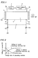
- Figure 1 is a diagram schematically illustrating a configuration around a laser cavity unit in a laser oscillation apparatus according to the present invention.
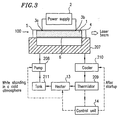
- Figure 2 is a diagram illustrating the relationship between the voltage ratio of grounding resistors and the respective absolute values of voltages to ground at an anode and a cathode of a DC high voltage power source in the configuration shown in Figure 1 .
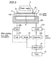
- Figure 3 is a diagram schematically illustrating an exemplary configuration of a cooling mechanism which can be used along with the laser cavity unit of the laser oscillation apparatus according to the present invention.
- Figure 4 shows diagrams provided for illustrating the operation of the cooling mechanism as shown in Figure 3 , and specifically: the portion (a) of Figure 4 is a diagram schematically illustrating the change in the oil temperature in the cooling mechanism shown in Figure 3 from shutdown to some time after subsequent start-up; the portions (b), (c) and (d) of Figure 4 are diagrams illustrating the operation timing of a pump, a heater and a cooler in the cooling mechanism as shown in Figure 3 , respectively; and the portion (e) of Figure 4 is a diagram schematically illustrating the change in the laser output of the laser oscillation apparatus after start-up when used with the cooling mechanism shown in Figure 3 .
- Figure 5 is a diagram schematically illustrating an exemplary configuration of another cooling mechanism which can be used along with the laser cavity unit of the laser oscillation apparatus according to the present invention.
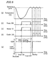
- Figure 6 shows diagrams provided for illustrating the operation of the cooling mechanism as shown in Figure 5 , and specifically: the portion (a) of Figure 6 is a diagram schematically illustrating the change in the oil temperature in the cooling mechanism shown in Figure 5 from shutdown to some time after subsequent start-up; the portions (b), (c) and (d) of Figure 6 are diagrams illustrating the operation timing of a pump, a heater and a cooler in the cooling mechanism as shown in Figure 5 , respectively; and the portion (e) of Figure 6 is a diagram schematically illustrating the change in the laser output of the laser oscillation apparatus after start-up when used with the cooling mechanism shown in Figure 6 .
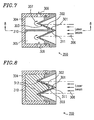
- Figure 7 is a cross-sectional view schematically illustrating a configuration of a laser light absorption unit according to the present invention.
- Figure 8 is a cross-sectional view taken along the line 8-8 in Figure 7 .
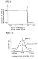
- Figure 9 is a diagram illustrating the relationship between thermal conductivity of a coupling material and temperature in the central portion of the light-receiving surface in the configuration of the laser light absorption unit shown in Figures 7 and 8 .
- Figure 10 is a diagram illustrating a measured result of the temperature distribution in the heat-exchanging surface in the configuration of the laser light absorption unit shown in Figures 7 and 8 .
- Figure 11 is a cross-sectional view schematically illustrating a configuration of another laser light absorption unit according to the present invention.
- Figure 12 is a cross-sectional view taken along the line 12-12 in Figure 11 .
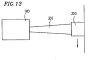
- Figure 13 is a diagram schematically illustrating positional relationship of the laser light absorption unit with respect to the optical path.
- Figure 14 is a diagram schematically illustrating a configuration around a laser cavity unit in a conventional laser oscillation apparatus.
- Figure 15 is a diagram schematically illustrating an exemplary configuration of a cooling mechanism which can be used along with the laser cavity unit of a conventional laser oscillation apparatus.
- Figure 16 shows diagrams provided for illustrating the operation of the conventional cooling mechanism as shown in Figure 15 , and specifically: the portion (a) of Figure 16 is a diagram schematically illustrating the change in the oil temperature in the conventional cooling mechanism shown in Figure 15 from shutdown to some time after subsequent start-up; the portions (b) and (c) of Figure 16 are diagrams illustrating the operation timing of a pump and a cooler in the conventional cooling mechanism as shown in Figure 15 , respectively; and the portion (d) of Figure 16 is a diagram schematically illustrating the change in the laser output of the laser oscillation apparatus after start-up when used with the cooling mechanism shown in Figure 15 .
- Figure 17 is a cross-sectional view schematically illustrating a configuration of a conventional laser light absorption unit.
- Figure 18 is a cross-sectional view schematically illustrating a configuration of another conventional light absorption unit.
- Figures 19 is a cross-sectional view schematically illustrating a configuration of yet another conventional light absorption unit.
- Figure 1 is a diagram schematically illustrating a configuration around a laser cavity unit 100 in a laser oscillation apparatus according to the present invention.
- a laser cavity unit 100 includes a laser tube 6 , a partially-transmissive reflection mirror 4 , and a total reflection mirror 5 .
- a high voltage is applied from a DC high voltage power source 2 via discharge electrodes 3a and 3b to a gaseous laser medium 1 contained in the laser tube 6 so as to generate a glow discharge.
- a blower 7 and a laser medium cooler 8 are serially connected to the laser tube 6 via a laser medium conduits 9a and 9b .
- the laser medium 1 is forcibly circulated by the blower 7 .
- the gaseous laser medium 1 heated by the glow discharge, passes through the laser medium conduit 9b , is cooled by the laser medium cooler 8 , passes through the blower 7 and laser medium conduit 9a , and then is sent back to a glow discharge space in the laser tube 6 .
- the total reflection mirror 5 is provided at one end of the laser tube 6 , and the partially-transmissive reflection mirror 4 is provided at the other end thereof. Laser light generated by a discharge passes through the partially-transmissive reflection mirror 4 and exits the laser tube 6 .
- the DC high voltage power source 2 is directly connected to the discharge electrodes 3a and 3b via feeder cables 11a and 11b .
- an anode and a cathode of the DC high voltage power source 2 which are respectively connected to the discharge electrodes 3a and 3b , are grounded via grounding resistors 12a and 12b .
- grounding resistors 12a and 12b are connected to the anode and the cathode, respectively, of the DC high voltage power source 2 , voltage to ground appearing at the discharge electrodes 3a and 3b are determined by the output voltage of the DC high voltage power source 2 and the ratio between the resistance values (i.e., the partial voltage ratio) of the grounding resistors 12a and 12b .
- the voltage to ground of each of the discharge electrodes 3a and 3b can be made lower than that of the conventional configuration.
- the anti-breakdown level required for the feeder cables 11a and 11b , which connect the DC high voltage power source 2 to the discharge electrodes 3a and 3b can be reduced as compared to the conventional configuration.
- the insulation distance between the discharge electrodes 3a and 3b and other components disposed around the discharge electrodes 3a and 3b can also be reduced as compared to the conventional configuration.
- Figure 2 illustrates the relationship between the ratio of resistance values of the grounding resistors 12a and 12b (i.e., the partial voltage ratio) and the respective absolute values of voltages to ground at the anode and the cathode of the DC high voltage power source 2 .
- E represents the output voltage value of the DC high voltage power source 2 .
- the anode and the cathode of the DC high voltage power source 2 are respectively connected to the discharge electrodes 3a and 3b via the feeder cables 11a and 11b .
- a voltage drop across the feeder cable 11a or 11b is negligible, and therefore, the vertical axis in Figure 2 can be considered to represent the voltages to ground of the discharge electrodes 3a and 3b .
- the partial voltage ratio is far removed from 1
- the voltages to ground of the anode and the cathode of the DC high voltage power source 2 are still lower than the maximum level thereof (i.e., the output voltage level E of the DC high voltage power source 2 ), which can appear at the discharge electrode in the conventional configuration without the grounding resistors.
- the above-described effects can be realized, such as the reduction in the anti-breakdown level required for the feeder cable 11a or 11b , and the improvement of the freedom in design around the discharge electrodes 3a and 3b .
- the laser oscillation apparatus includes the laser cavity unit 100 for generating laser light by discharge-induced excitation of the gaseous laser medium 1 in the laser tube 6 and optical amplification of the generated light by means of a pair of the optical amplification mirrors 4 and 5 , and the DC high voltage power source 2 for activating a discharge.
- the grounding resistors 12a and 12b are respectively connected to the anode and the cathode of the DC high voltage power source 2 . This enables the voltages to ground of the discharge electrodes 3a and 3b which are respectively connected to the anode and the cathode of the DC high voltage power source 2 to be lowered.
- This allows for use of a feeder cable whose anti-breakdown level is low, and also reduces the insulation distance around the discharge electrodes 3a and 3b so as to increase the freedom in design of the entire oscillation apparatus, thereby facilitating the designing of the apparatus.
- Figure 3 is a diagram schematically illustrating an exemplary configuration of a cooling mechanism which can be used along with the laser cavity unit 100 of the laser oscillation apparatus. Elements in Figure 3 which are also shown in Figure 1 are denoted by the same reference numerals and will not be further described.
- optical components such as the partially-transmissive reflection mirror 4 and the total reflection mirror 5 are held by the holder 207 .
- a coolant for example, oil is circulated within the holder 207 by means of the pump 208 to cool the holder 207 .
- such a cooling mechanism using the coolant includes the tank 211 , the pump 208 for supplying the oil into the holder 207 , the cooler 210 for cooling the oil, and the thermistor 209 for detecting the oil temperature.
- a heater 13 for heating the oil is provided between the thermistor 209 and the tank 211 .
- a control unit 14 controls the operation of the cooler 210 and the heater 13 based on the oil temperature detected by the thermistor 209 .
- the heater 13 is provided in the coolant conduit, and the control unit 14 is used to appropriately control the operation of the heater 13 so as to control the oil temperature by heating the oil in a laser oscillation start-up.
- the control unit 14 is used to appropriately control the operation of the heater 13 so as to control the oil temperature by heating the oil in a laser oscillation start-up.
- the oil temperature is detected by the thermistor 209 while the laser oscillation apparatus is standing.
- the control unit 14 activates the pump 208 and the heater 13 .
- the holder 207 is heated by circulating heated oil therein so that the temperature of the holder 207 is raised to an appropriate value even while standing.
- the oil is cooled by controlling the operation of the cooler 210 based on the oil temperature detected by the thermistor 209 , thereby maintaining the temperature of the holder 207 at an appropriate value.
- the positional parallel relationship between the partially-transmissive reflection mirror 4 and the total reflection mirror 5 can be always maintained even when the laser oscillation apparatus is placed in a cold atmosphere.
- Figure 4 shows diagrams provided for illustrating the operation of the cooling mechanism for optical components in the laser oscillation apparatus shown in Figure 3 .
- the portion (a) of Figure 4 schematically illustrates the change in the temperature of the oil in the cooling mechanism from shutdown to some time after subsequent start-up.
- the temperature indicated therein can be considered as the temperature of the holder 207 , which is cooled by the oil.
- the portion (e) of Figure 4 is a diagram schematically illustrating the change in the laser output of the laser oscillation apparatus after start-up, and the portions (b), (c) and (d) of figure 4 illustrate the operation timing of the pump 208 , the heater 13 and the cooler 210 , respectively.
- the pump 208 and the heater 13 are intermittently operated at appropriate times as shown in the portions (b) and (c) of Figure 4 .
- the oil temperature is maintained at around a predetermined operating point temperature while standing in a cold atmosphere.
- a stable laser oscillation can be achieved in a short period of time after start-up as shown in the portion (e) of Figure 4 .
- control unit 14 acts to cause the cooler 210 to operate at an appropriate time as shown in the portion (d) of Figure 4 .
- the oil temperature is typically maintained at around 28°C.
- Figure 5 is a diagram schematically illustrating an exemplary configuration of another cooling mechanism which can be used along with the laser cavity unit of the laser oscillation apparatus. Elements in Figure 5 which are also shown in Figure 3 are denoted by the same reference numerals and will not be further described.
- Figure 6 shows diagrams provided for illustrating the operation of the cooling mechanism for optical components in the laser oscillation apparatus shown in Figure 5 .
- the portion (a) of Figure 6 schematically illustrates the change in the temperature of the oil in the cooling mechanism from shutdown to some time after subsequent start-up. The temperature indicated therein can be considered as the temperature of the holder 207 , which is cooled by the oil.
- the portions (e) of Figure 6 is a diagram schematically illustrating the change in the laser output of the laser oscillation apparatus after start-up, and the portions (b), (c) and (d) of Figure 6 illustrate the operation timing of the pump 208 , the heater 13 and the cooler 210 , respectively.
- a timer 15 is further added to the control unit 14 in the configuration previously described with reference to Figure 3 .
- the timer 15 acts to cause the heater 13 and the pump 208 to operate for a certain period of time for heating the oil so that the oil temperature recovers to around the predetermined operating point temperature.
- the timer 15 can act to cause the heater 13 and the pump 208 to operate for a certain period of time from a predetermined time prior to the scheduled start-up time for heating the oil. This allows the oil temperature to recover to around the predetermined operating point temperature by the scheduled time for starting up the laser oscillation apparatus.
- Such a configuration also allows a stable laser oscillation to be achieved in a short period of time after the start-up as shown in the portion (e) of Figure 6 .
- control unit 14 acts to cause the cooler 210 to operate at an appropriate time as shown in the portion (d) of Figure 6 . This allows for a stable operation of the laser oscillation apparatus.
- the heater 13 in addition to the pump 208 , thermistor 209 and the cooler 210 is provided in the coolant conduit to the holder 207 which holds optical components such as the partially-transmissive reflection mirror 4 and the total reflection mirror 5 .
- the control unit 14 is provided to appropriately control the operation of the pump 208 , the heater 13 and the cooler 210 .
- the present invention is described by way of an example where oil is used as the coolant for adjusting the temperature of the holder 207 .
- the coolant to be used for this purpose is not limited to oil, but water, solution containing ethylene glycol, solution containing polyhydric alcohol, or the like can also be used.
- the thermistor 209 is used for the purpose of detecting the temperature of the coolant such as oil in the above description.
- any temperature sensors other than a thermistor such as platinum-type temperature detector, thermo couple, or the like, can also be used for this purpose.
- Figure 13 is a diagram schematically illustrating positional relationship of a laser light absorption unit 300 with respect to an optical path of a laser light 306 emitted from the laser cavity unit 100 .
- the laser light absorption unit 300 is provided on the optical path of the laser light 306 irradiated from the laser cavity unit 100 in the laser oscillation apparatus. Normally, the laser light absorption unit 300 is located so as to block the optical path of the laser light 306 , thereby preventing the laser light 306 generated in the laser cavity unit 100 from exiting the laser oscillation apparatus, and thus functioning as a safety apparatus.
- the laser light absorption unit 300 is shifted aside from the optical path of the laser light 306 , e.g., as shown by an arrow in Figure 13 , so that the laser light 306 exits the laser oscillation apparatus.
- the conventional laser light absorption unit has non-uniform heat exchange due to the non-uniformity of the temperature distribution at the heat-exchanging surface, the imbalance of the coolant supply, or the like.
- the laser light absorption unit of the present invention is formed by coupling an inner cylinder having a conical configuration in which the light-receiving surface for receiving laser light and the heat-exchanging surface are provided on the respective front and rear surfaces of the configuration and an outer cylinder forming a path for a coolant between the outer cylinder and the heat-exchanging surface of the inner cylinder, and moreover, a flow path adjuster is provided in the path for the coolant.
- the flow path adjuster causes the coolant to flow in a concentrated manner in the vicinity of the central portion of the heat-exchanging surface of the inner cylinder. Furthermore, the flow path adjuster and the heat-exchanging surface are coupled together at the interface therebetween by using a coupling material having a thermal conductivity of about 10 W/m ⁇ K or greater.
- the laser light absorption unit of the present invention having such a structure, sufficient heat exchange is provided in the central portion of the heat-exchanging surface, where the temperature becomes highest due to the laser light absorption.
- the flow path adjuster is coupled to the heat-exchanging surface by using a coupling material having a thermal conductivity of about 10 W/m ⁇ K or greater.
- a coupling material having a thermal conductivity of about 10 W/m ⁇ K or greater.
- the flow path adjuster is formed of at least one or more flat fixed blades.
- the flow path adjuster of the present invention can be realized with a simple structure, and provides cost advantage.
- Figure 7 is a cross-sectional view schematically illustrating a configuration of a laser light absorption unit 350 of the present invention.
- Figure 8 is a cross-sectional view taken along the line 8-8 in Figure 7 .
- the inner cylinder 301 is provided at an opening of the outer cylinder 304 .
- the inner cylinder 301 includes the light-receiving surface 302 and the heat-exchanging surface 303 respectively on the front surface and the rear surface of the inner cylinder 301 .
- a space existing between the inner cylinder 301 and the outer cylinder 304 provides the path 305 for the coolant 307 .
- the inner cylinder 301 is formed of a metallic material having a high thermal conductivity, e.g., copper, aluminum, brass, stainless steel, or the like.
- Water can be used as the coolant 307 , for example.
- oil, solution containing ethylene glycol, solution containing polyhydric alcohol, or the like can be used as the coolant 307 .
- the light-receiving surface 302 is formed by combining a plurality of conical configurations. Each of the conical surfaces of the conical configurations forms an angle of about 30° or less with respect to the incident axis of the laser light 306 so that the incident laser light 306 is not directed externally after being reflected. Moreover, the light-receiving surface 302 is coated with a material having a high absorptivity for the wavelength of the laser light 306 to be oscillated. The laser light 306 incident upon the light-receiving surface 302 is quickly absorbed, and the heat thereof is transferred by conduction to the heat-exchanging surface 303 .
- a flow path adjuster 310 formed of the fixed flat blade is provided within the path 305 for the coolant 307 .
- the flow path adjuster 310 is formed of, for example, a metallic material having a high thermal conductivity such as copper, aluminum, brass, stainless steel, or the like.
- the coolant 307 introduced into the path 305 through an inlet 308 exchanges heat at the heat-exchanging surface 303 , and is drained through an outlet 309 .
- the coolant 307 is blocked by the flow path adjuster 310 so that the coolant 307 passes in a concentrated manner through an opening 311 formed in the vicinity of the central portion of the heat-exchanging surface 303 .
- the heat-exchanging surface 303 and the flow path adjuster 310 are coupled together at an interface 312 therebetween (see Figure 8 ) by using an appropriate coupling material.
- the coupling material is a material having a thermal conductivity of about 10 W/m ⁇ K or greater.
- a brazing filler metal can be used, for example.
- materials such as a metallic material e.g., copper, aluminum, brass, stainless steel, or the like can be used as the coupling material.
- the thermal conductivity of the coupling material when the thermal conductivity of the coupling material is about 10 W/m ⁇ K or greater, the temperature of the light-receiving surface 302 around the center thereof stands at about 400K.
- the thermal conductivity of the coupling material when the thermal conductivity of the coupling material is less than about 10 W/m ⁇ K, the temperature of the light-receiving surface 302 around the center thereof rapidly increases. Therefore, in order for the coupling material to serve as a thermal conductor, the thermal conductivity thereof must be about 10 W/m ⁇ K or greater.
- the laser light 306 incident upon the light-receiving surface 302 is absorbed by the light-receiving surface 302 , and the heat thereof is transferred by conduction to the heat-exchanging surface 303 through the inner cylinder 301 .
- a portion of heat transferred to the heat-exchanging surface 303 is further transferred to the flow path adjuster 310 through the interface 312 .
- the flow path adjuster 310 itself functions as the heat-exchanging surface, so that the temperature increase at the center of the heat-exchanging surface 303 is reduced.
- Figure 10 illustrates an exemplary thermographic measurement of the temperature distribution in the heat-exchanging surface 303 of the inner cylinder 301 .
- the horizontal axis represents the location on the heat-exchanging surface 303
- the vertical axis represents the measured temperature (K) at each position.
- the measured data for the present invention (represented by the dashed line) shows that, as compared to the measured data for the conventional configuration (represented by the solid line), the temperature in the central portion is reduced while the temperature in the peripheral portion is increased.
- the temperature on the whole heat-exchanging surface 303 is more balanced.
- the dissipation of heat has been achieved only on the heat-exchanging surface 303 .
- heat in the central portion of the heat-exchanging surface 303 is transferred to the flow path adjuster 310 through thermal conduction as described above, so that the dissipation of the absorbed heat is also provided on the surface of the flow path adjuster 310 .
- the coolant 307 passes in a concentrated manner through the opening 311 formed in the vicinity of the central portion of the heat-exchanging surface 303 , as shown in Figures 7 and 8 , the heat exchange performance at the central portion of the heat-exchanging surface 303 is improved. Due to such a dual effect, the laser light absorption unit 350 of the present invention allows for a stable heat exchange as a whole.
- the damage to the light-receiving surface 302 can be minimized, thereby allowing for a long-term stable use of the apparatus.
- Figure 11 is a cross-sectional view schematically illustrating a configuration of another laser light absorption unit 360 according to the present invention.
- Figure 12 is a cross-sectional view taken along the line 12-12 in Figure 11 .
- Elements in Figures 11 and 12 which are also shown in Figures 7 and 8 are denoted by the same reference numerals and will not be further described.
- the flow path adjuster 310 is formed of two fixed flat blades orthogonally crossing each other. Due to such a configuration, as compared to the above-described laser light absorption unit 350 , the contact area at the interface 312 between the heat-exchanging surface 303 and the flow path adjuster 310 is increased, so that a further improved heat conduction effect can be realized. Moreover, since the surface area of the flow path adjuster 310 is increased, the heat exchange area in the entire apparatus is increased, thereby also improving the diffusion effect for the absorbed heat.
- the flow path adjuster is provided in the coolant path so that the coolant flows in a concentrated manner in the vicinity of the central portion of the heat-exchanging surface of the conically-shaped inner cylinder. Moreover, at the interface between the flow path adjuster and the heat-exchanging surface, a coupling material having a thermal conductivity of about 10 W/m ⁇ K or greater is provided. Thus, the temperature distribution on the light-receiving surface is made uniform, thus allowing for a long-term stable laser light absorption.
- connection circuit for the laser cavity unit (the discharge electrodes) of the DC high voltage power source for the laser oscillation apparatus, the cooling mechanism for the holder of the optical components, and the laser light absorption unit, respectively.
- the contents of the respective examples are not only applicable individually, but also applicable in combination.
- a gas laser e.g., a CO 2 laser
- application of the contents of the present invention is not limited to such a gas laser.
- similar effects can be realized when applied to a laser oscillation apparatus including a laser cavity unit of other types, e.g., a YAG laser or the like.
Landscapes
- Physics & Mathematics (AREA)
- Electromagnetism (AREA)
- Engineering & Computer Science (AREA)
- Plasma & Fusion (AREA)
- Optics & Photonics (AREA)
- Mechanical Engineering (AREA)
- Lasers (AREA)
Priority Applications (2)
| Application Number | Priority Date | Filing Date | Title |
|---|---|---|---|
| EP04018241A EP1475866B1 (fr) | 1996-07-01 | 1997-06-30 | Appareil laser |
| EP04018242A EP1475867B1 (fr) | 1996-07-01 | 1997-06-30 | Appareil laser |
Applications Claiming Priority (9)
| Application Number | Priority Date | Filing Date | Title |
|---|---|---|---|
| JP170858/96 | 1996-07-01 | ||
| JP17085896 | 1996-07-01 | ||
| JP8170858A JPH1022553A (ja) | 1996-07-01 | 1996-07-01 | 気体レーザ発振装置 |
| JP21094996 | 1996-08-09 | ||
| JP8210949A JPH1056228A (ja) | 1996-08-09 | 1996-08-09 | ガスレーザ発振装置 |
| JP210949/96 | 1996-08-09 | ||
| JP251093/96 | 1996-09-24 | ||
| JP25109396A JP3503358B2 (ja) | 1996-09-24 | 1996-09-24 | レーザビーム吸収装置 |
| JP25109396 | 1996-09-24 |
Related Child Applications (2)
| Application Number | Title | Priority Date | Filing Date |
|---|---|---|---|
| EP04018241A Division EP1475866B1 (fr) | 1996-07-01 | 1997-06-30 | Appareil laser |
| EP04018242A Division EP1475867B1 (fr) | 1996-07-01 | 1997-06-30 | Appareil laser |
Publications (3)
| Publication Number | Publication Date |
|---|---|
| EP0817338A2 true EP0817338A2 (fr) | 1998-01-07 |
| EP0817338A3 EP0817338A3 (fr) | 1998-12-16 |
| EP0817338B1 EP0817338B1 (fr) | 2004-10-06 |
Family
ID=27323394
Family Applications (3)
| Application Number | Title | Priority Date | Filing Date |
|---|---|---|---|
| EP04018241A Expired - Lifetime EP1475866B1 (fr) | 1996-07-01 | 1997-06-30 | Appareil laser |
| EP04018242A Expired - Lifetime EP1475867B1 (fr) | 1996-07-01 | 1997-06-30 | Appareil laser |
| EP97110646A Expired - Lifetime EP0817338B1 (fr) | 1996-07-01 | 1997-06-30 | Appareil laser |
Family Applications Before (2)
| Application Number | Title | Priority Date | Filing Date |
|---|---|---|---|
| EP04018241A Expired - Lifetime EP1475866B1 (fr) | 1996-07-01 | 1997-06-30 | Appareil laser |
| EP04018242A Expired - Lifetime EP1475867B1 (fr) | 1996-07-01 | 1997-06-30 | Appareil laser |
Country Status (3)
| Country | Link |
|---|---|
| US (3) | US6078604A (fr) |
| EP (3) | EP1475866B1 (fr) |
| DE (3) | DE69738632T2 (fr) |
Cited By (3)
| Publication number | Priority date | Publication date | Assignee | Title |
|---|---|---|---|---|
| WO2000074183A1 (fr) * | 1999-06-01 | 2000-12-07 | Komatsu Ltd. | Dispositif laser ultraviolet |
| WO2013178950A1 (fr) * | 2012-06-01 | 2013-12-05 | Snecma | Procédé et dispositif de perçage d'une pièce par impulsions laser |
| WO2015193660A1 (fr) * | 2014-06-16 | 2015-12-23 | Apollo Fire Detectors Limited | Absorbeur de lumière conique pour détecteur de fumée |
Families Citing this family (11)
| Publication number | Priority date | Publication date | Assignee | Title |
|---|---|---|---|---|
| US6796710B2 (en) * | 2001-06-08 | 2004-09-28 | Ethicon Endo-Surgery, Inc. | System and method of measuring and controlling temperature of optical fiber tip in a laser system |
| US6775315B1 (en) * | 2001-06-08 | 2004-08-10 | Scott Allen Nield | Apparatus and method of directing a laser beam to a thermally managed beam dump in a laser system |
| US6765941B2 (en) * | 2001-12-03 | 2004-07-20 | Agfa Corporation | Method and apparatus for cooling a self-contained laser head |
| US20050209142A1 (en) * | 2002-11-20 | 2005-09-22 | Goran Bertilsson | Compounds and methods for increasing neurogenesis |
| JP4593073B2 (ja) * | 2002-12-26 | 2010-12-08 | 株式会社半導体エネルギー研究所 | レーザ照射装置 |
| CN100341210C (zh) * | 2005-02-23 | 2007-10-03 | 中国科学院上海光学精密机械研究所 | 高效率低阶模横流co2激光器 |
| EP1758216B1 (fr) * | 2005-08-26 | 2013-04-10 | Trumpf Laser- und Systemtechnik GmbH | Diaphragme à deux niveaux pour un faisceau laser |
| JP4271247B2 (ja) | 2007-04-10 | 2009-06-03 | ファナック株式会社 | レーザ装置 |
| DE102008013816B4 (de) * | 2008-03-12 | 2010-09-16 | Trumpf Werkzeugmaschinen Gmbh + Co. Kg | Rückgewinnung von Energie aus einem Laserbearbeitungssystem |
| KR102404575B1 (ko) * | 2015-10-12 | 2022-06-03 | 삼성디스플레이 주식회사 | 증착 장치와 이를 이용한 유기 발광 디스플레이 장치의 제조 방법 |
| CN106025774B (zh) * | 2016-07-28 | 2019-03-12 | 中国科学院电子学研究所 | 一种增益介质自流动蒸气室及dpal激光器 |
Family Cites Families (22)
| Publication number | Priority date | Publication date | Assignee | Title |
|---|---|---|---|---|
| US3842365A (en) * | 1973-05-30 | 1974-10-15 | Westinghouse Electric Corp | Pulse glow generation for laser systems |
| US4156208A (en) * | 1977-05-04 | 1979-05-22 | Gte Sylvania Incorporated | Mechanism for initiating discharge in a high power gas transport laser |
| US4147995A (en) * | 1977-08-19 | 1979-04-03 | The United States Of America As Represented By The Secretary Of The Air Force | Foil moderated radioactive preionization system for gas lasers |
| US4420834A (en) * | 1981-06-10 | 1983-12-13 | The United States Of America As Represented By The Secretary Of The Air Force | Flow attenuator for use with liquid cooled laser mirrors |
| JPS5863186A (ja) * | 1981-10-09 | 1983-04-14 | Matsushita Electric Ind Co Ltd | レ−ザエネルギ−開閉装置 |
| JPS5879787A (ja) * | 1981-11-06 | 1983-05-13 | Olympus Optical Co Ltd | レ−ザ出力可変装置 |
| JPS60147184A (ja) * | 1984-01-11 | 1985-08-03 | Matsushita Electric Ind Co Ltd | ガスレ−ザ発振装置 |
| US4686682A (en) * | 1984-10-09 | 1987-08-11 | Mitsubishi Denki Kabushiki Kaisha | Discharge excitation type short pulse laser device |
| DE8433460U1 (de) * | 1984-11-15 | 1985-03-21 | Gerhardt, Harald, Dr., 3012 Langenhagen | Gaslaserrohr |
| US4722091A (en) * | 1986-02-24 | 1988-01-26 | Rca Corporation | Hybrid laser power supply |
| US4740981A (en) * | 1986-10-10 | 1988-04-26 | Stemmerich, Inc. | Temperature controller for gas laser resonator |
| US4803439A (en) * | 1987-09-08 | 1989-02-07 | Grumman Aerospace Corportion | Glass bead laser amplifier with phase conjugate mirror |
| US4864098A (en) * | 1988-05-19 | 1989-09-05 | Rofin-Sinar, Inc. | High powered beam dump |
| JPH02137059A (ja) * | 1988-11-12 | 1990-05-25 | Talent Lab Inc | 文字処理装置における発音・音調による漢字入力方法 |
| JPH02148779A (ja) * | 1988-11-29 | 1990-06-07 | Mitsubishi Electric Corp | レーザ発振器 |
| JPH02137059U (fr) * | 1988-12-19 | 1990-11-15 | ||
| JP2913957B2 (ja) * | 1990-12-27 | 1999-06-28 | 松下電器産業株式会社 | 放電励起ガスレーザ装置 |
| US5311528A (en) * | 1991-08-30 | 1994-05-10 | Hoya Corporation | Solid-state laser device capable of stably producing an output laser beam at high power |
| WO1993010583A1 (fr) * | 1991-11-22 | 1993-05-27 | Omnichrome Corporation | Lasers a miroir interne stabilise par un liquide |
| EP0618653B1 (fr) * | 1993-03-30 | 1997-07-16 | Nec Corporation | Méthode de stabilisation de la fréquence d'un laser à semi-conducteur et source de lumière stabilisée en fréquence |
| JP2725594B2 (ja) * | 1994-04-28 | 1998-03-11 | 松下電器産業株式会社 | 気体レーザ装置 |
| US5471491A (en) * | 1994-11-15 | 1995-11-28 | Hughes Aircraft Company | Method and structure for impingement cooling a laser rod |
-
1997
- 1997-06-30 EP EP04018241A patent/EP1475866B1/fr not_active Expired - Lifetime
- 1997-06-30 US US08/885,101 patent/US6078604A/en not_active Expired - Lifetime
- 1997-06-30 EP EP04018242A patent/EP1475867B1/fr not_active Expired - Lifetime
- 1997-06-30 DE DE69738632T patent/DE69738632T2/de not_active Expired - Lifetime
- 1997-06-30 DE DE69737538T patent/DE69737538T2/de not_active Expired - Lifetime
- 1997-06-30 DE DE69731029T patent/DE69731029T2/de not_active Expired - Lifetime
- 1997-06-30 EP EP97110646A patent/EP0817338B1/fr not_active Expired - Lifetime
-
1998
- 1998-10-29 US US09/182,539 patent/US6021151A/en not_active Expired - Lifetime
- 1998-10-29 US US09/182,538 patent/US6266352B1/en not_active Expired - Lifetime
Cited By (11)
| Publication number | Priority date | Publication date | Assignee | Title |
|---|---|---|---|---|
| US6785319B1 (en) | 1999-01-06 | 2004-08-31 | Komatsu Ltd. | Ultraviolet laser device |
| WO2000074183A1 (fr) * | 1999-06-01 | 2000-12-07 | Komatsu Ltd. | Dispositif laser ultraviolet |
| WO2013178950A1 (fr) * | 2012-06-01 | 2013-12-05 | Snecma | Procédé et dispositif de perçage d'une pièce par impulsions laser |
| FR2991214A1 (fr) * | 2012-06-01 | 2013-12-06 | Snecma | Procede de percage d'une piece par impulsions laser |
| CN104379300A (zh) * | 2012-06-01 | 2015-02-25 | 斯奈克玛 | 用激光器脉冲钻孔工件的方法和装置 |
| CN104379300B (zh) * | 2012-06-01 | 2016-10-19 | 斯奈克玛 | 用激光器脉冲钻孔工件的方法和装置 |
| US9713855B2 (en) | 2012-06-01 | 2017-07-25 | Snecma | Method and device for drilling a workpiece with laser pulses |
| WO2015193660A1 (fr) * | 2014-06-16 | 2015-12-23 | Apollo Fire Detectors Limited | Absorbeur de lumière conique pour détecteur de fumée |
| CN106574989A (zh) * | 2014-06-16 | 2017-04-19 | 英国阿波罗防火探测器有限公司 | 用于烟雾探测器的圆锥形光吸收器 |
| US10019879B2 (en) | 2014-06-16 | 2018-07-10 | Apollo Fire Detectors Limited | Conical light absorber for smoke detector |
| CN106574989B (zh) * | 2014-06-16 | 2019-12-03 | 英国阿波罗防火探测器有限公司 | 用于烟雾探测器的圆锥形光吸收器 |
Also Published As
| Publication number | Publication date |
|---|---|
| US6021151A (en) | 2000-02-01 |
| DE69731029D1 (de) | 2004-11-11 |
| US6078604A (en) | 2000-06-20 |
| US6266352B1 (en) | 2001-07-24 |
| DE69738632D1 (de) | 2008-05-21 |
| DE69738632T2 (de) | 2009-06-10 |
| EP1475866B1 (fr) | 2007-03-28 |
| EP1475867B1 (fr) | 2008-04-09 |
| DE69737538D1 (de) | 2007-05-10 |
| DE69731029T2 (de) | 2005-03-03 |
| EP1475867A2 (fr) | 2004-11-10 |
| EP0817338A3 (fr) | 1998-12-16 |
| DE69737538T2 (de) | 2007-12-13 |
| EP1475867A3 (fr) | 2005-01-05 |
| EP1475866A2 (fr) | 2004-11-10 |
| EP1475866A3 (fr) | 2005-01-12 |
| EP0817338B1 (fr) | 2004-10-06 |
Similar Documents
| Publication | Publication Date | Title |
|---|---|---|
| US6021151A (en) | Laser oscillation apparatus | |
| US6115396A (en) | Control system for a laser with multiple solid state rods | |
| US5311528A (en) | Solid-state laser device capable of stably producing an output laser beam at high power | |
| US6504858B2 (en) | Lasers with low doped gain medium | |
| EP1160940B1 (fr) | Amplificateur optique comprenant un matériaux de gain en plaque zig-zag pompé longitudinalement | |
| EP0226790B1 (fr) | Laser à l'état solide à structure unitaire | |
| Erhard et al. | Pumping schemes for multi-kW thin disk lasers | |
| US5353293A (en) | Hybrid cooled ion laser | |
| JP2003198018A (ja) | 光励起型固体レーザ発振器 | |
| JP2002535852A (ja) | ファネル結合ポンプソースを備えたダイオードポンプレーザ | |
| Golla et al. | High power continuous-wave diode-laser-pumped Nd: YAG laser | |
| JPH08204263A (ja) | 半導体レーザ励起レーザ発振器 | |
| US5982792A (en) | Solid-state laser device | |
| US5170406A (en) | High-power, end-pumped solid state laser | |
| Giesen et al. | Diode-pumped high-power solid-state laser: concept and first results with Yb: YAG | |
| US5848081A (en) | Insulated water cooled gain medium assembly for a laser system | |
| US5331653A (en) | Solid-state laser device | |
| GB2193371A (en) | Laser pumped by electromagnetic radiation | |
| Golla et al. | High power operation of Nd: YAG rod lasers pumped by fiber-coupled diode lasers | |
| Giesen et al. | Recent results of the scalable diode-pumped Yb: YAG thin disk laser | |
| JPH11261137A (ja) | レーザ装置 | |
| WO1999060673A2 (fr) | Laser dope | |
| JP4003725B2 (ja) | 固体レーザ装置およびレーザ加工装置 | |
| Golla et al. | Design and operation of a 250 W CW, diode laser side-pumped Nd: YAG rod laser | |
| JP2002111106A (ja) | 固体レーザ励起モジュール |
Legal Events
| Date | Code | Title | Description |
|---|---|---|---|
| PUAI | Public reference made under article 153(3) epc to a published international application that has entered the european phase |
Free format text: ORIGINAL CODE: 0009012 |
|
| 17P | Request for examination filed |
Effective date: 19970721 |
|
| AK | Designated contracting states |
Kind code of ref document: A2 Designated state(s): DE FR IT NL |
|
| PUAL | Search report despatched |
Free format text: ORIGINAL CODE: 0009013 |
|
| AK | Designated contracting states |
Kind code of ref document: A3 Designated state(s): AT BE CH DE DK ES FI FR GB GR IE IT LI LU MC NL PT SE |
|
| AKX | Designation fees paid |
Free format text: DE FR IT NL |
|
| 17Q | First examination report despatched |
Effective date: 20011127 |
|
| GRAP | Despatch of communication of intention to grant a patent |
Free format text: ORIGINAL CODE: EPIDOSNIGR1 |
|
| RIN1 | Information on inventor provided before grant (corrected) |
Inventor name: HAYASHIKAWA, HIROYUKI Inventor name: YAMASHITA, TAKAYUKI Inventor name: EGUCHI, SATOSHI |
|
| GRAS | Grant fee paid |
Free format text: ORIGINAL CODE: EPIDOSNIGR3 |
|
| GRAA | (expected) grant |
Free format text: ORIGINAL CODE: 0009210 |
|
| AK | Designated contracting states |
Kind code of ref document: B1 Designated state(s): DE FR IT NL |
|
| REF | Corresponds to: |
Ref document number: 69731029 Country of ref document: DE Date of ref document: 20041111 Kind code of ref document: P |
|
| ET | Fr: translation filed | ||
| PLBE | No opposition filed within time limit |
Free format text: ORIGINAL CODE: 0009261 |
|
| STAA | Information on the status of an ep patent application or granted ep patent |
Free format text: STATUS: NO OPPOSITION FILED WITHIN TIME LIMIT |
|
| 26N | No opposition filed |
Effective date: 20050707 |
|
| REG | Reference to a national code |
Ref country code: FR Ref legal event code: PLFP Year of fee payment: 19 |
|
| PGFP | Annual fee paid to national office [announced via postgrant information from national office to epo] |
Ref country code: DE Payment date: 20150624 Year of fee payment: 19 |
|
| PGFP | Annual fee paid to national office [announced via postgrant information from national office to epo] |
Ref country code: FR Payment date: 20150608 Year of fee payment: 19 Ref country code: NL Payment date: 20150510 Year of fee payment: 19 |
|
| PGFP | Annual fee paid to national office [announced via postgrant information from national office to epo] |
Ref country code: IT Payment date: 20150625 Year of fee payment: 19 |
|
| REG | Reference to a national code |
Ref country code: DE Ref legal event code: R119 Ref document number: 69731029 Country of ref document: DE |
|
| REG | Reference to a national code |
Ref country code: NL Ref legal event code: MM Effective date: 20160701 |
|
| REG | Reference to a national code |
Ref country code: FR Ref legal event code: ST Effective date: 20170228 |
|
| PG25 | Lapsed in a contracting state [announced via postgrant information from national office to epo] |
Ref country code: DE Free format text: LAPSE BECAUSE OF NON-PAYMENT OF DUE FEES Effective date: 20170103 Ref country code: FR Free format text: LAPSE BECAUSE OF NON-PAYMENT OF DUE FEES Effective date: 20160630 |
|
| PG25 | Lapsed in a contracting state [announced via postgrant information from national office to epo] |
Ref country code: NL Free format text: LAPSE BECAUSE OF NON-PAYMENT OF DUE FEES Effective date: 20160701 |
|
| PG25 | Lapsed in a contracting state [announced via postgrant information from national office to epo] |
Ref country code: IT Free format text: LAPSE BECAUSE OF NON-PAYMENT OF DUE FEES Effective date: 20160630 |