EP0821831B1 - Lame de fusible femelle d'une seule piece, son boitier et perfectionnements y ayant trait - Google Patents
Lame de fusible femelle d'une seule piece, son boitier et perfectionnements y ayant trait Download PDFInfo
- Publication number
- EP0821831B1 EP0821831B1 EP96913051A EP96913051A EP0821831B1 EP 0821831 B1 EP0821831 B1 EP 0821831B1 EP 96913051 A EP96913051 A EP 96913051A EP 96913051 A EP96913051 A EP 96913051A EP 0821831 B1 EP0821831 B1 EP 0821831B1
- Authority
- EP
- European Patent Office
- Prior art keywords
- female
- fuse
- terminal
- forming
- terminals
- Prior art date
- Legal status (The legal status is an assumption and is not a legal conclusion. Google has not performed a legal analysis and makes no representation as to the accuracy of the status listed.)
- Expired - Lifetime
Links
Images





Classifications
-
- H—ELECTRICITY
- H01—ELECTRIC ELEMENTS
- H01H—ELECTRIC SWITCHES; RELAYS; SELECTORS; EMERGENCY PROTECTIVE DEVICES
- H01H69/00—Apparatus or processes for the manufacture of emergency protective devices
- H01H69/02—Manufacture of fuses
-
- H—ELECTRICITY
- H01—ELECTRIC ELEMENTS
- H01H—ELECTRIC SWITCHES; RELAYS; SELECTORS; EMERGENCY PROTECTIVE DEVICES
- H01H85/00—Protective devices in which the current flows through a part of fusible material and this current is interrupted by displacement of the fusible material when this current becomes excessive
- H01H85/02—Details
- H01H85/04—Fuses, i.e. expendable parts of the protective device, e.g. cartridges
- H01H85/041—Fuses, i.e. expendable parts of the protective device, e.g. cartridges characterised by the type
-
- H—ELECTRICITY
- H01—ELECTRIC ELEMENTS
- H01H—ELECTRIC SWITCHES; RELAYS; SELECTORS; EMERGENCY PROTECTIVE DEVICES
- H01H85/00—Protective devices in which the current flows through a part of fusible material and this current is interrupted by displacement of the fusible material when this current becomes excessive
- H01H85/02—Details
- H01H85/04—Fuses, i.e. expendable parts of the protective device, e.g. cartridges
- H01H85/041—Fuses, i.e. expendable parts of the protective device, e.g. cartridges characterised by the type
- H01H85/0411—Miniature fuses
- H01H85/0415—Miniature fuses cartridge type
- H01H85/0417—Miniature fuses cartridge type with parallel side contacts
-
- H—ELECTRICITY
- H01—ELECTRIC ELEMENTS
- H01H—ELECTRIC SWITCHES; RELAYS; SELECTORS; EMERGENCY PROTECTIVE DEVICES
- H01H85/00—Protective devices in which the current flows through a part of fusible material and this current is interrupted by displacement of the fusible material when this current becomes excessive
- H01H85/02—Details
- H01H85/04—Fuses, i.e. expendable parts of the protective device, e.g. cartridges
- H01H85/05—Component parts thereof
- H01H85/055—Fusible members
Definitions
- the present invention relates generally to electrical fuses. More particularly, this invention relates to female electrical fuses which are designed for connection into a fuse block having male terminal connections.
- Automobile and other female fuse assemblies commonly comprise a two-piece assembly heretofore having a box-like housing and an all metal one-piece female fuse secured therein.
- the female fuse has a pair of spaced apart female terminals which are accessible from one end of the housing where male terminal openings are placed in the housing to correspond to male blade-type terminals.
- the male blade-type terminals or conductors recently, typically extend from a mounting panel or male fuse block, as there has been a shift in the automotive industry toward the use of male terminal blocks.
- the female terminals are commonly closely encompassed by the housing walls.
- the female fuse also includes a fuse link extended, usually unsupported, between the female terminals.
- connection or transition between the female terminals and the fuse link begins at the center of one female terminal and extends linearly, from a side view, to the other female terminal, without any lateral movement from a top view. From this top view, the width of the fuse link is typically narrowed to create a fuse blowing portion.
- Some female fuses use an additional component with the fuse link, such as a ceramic member, for heat conduction purposes to achieve a desired fuse characteristic.
- the fuse link and additional component are commonly spaced close to the housing side walls for a reduced volume of used material.
- the above identified two-piece female fuse assembly, with a one piece fuse is generally disclosed in U.S. Patent Nos. 4,570,147 ( Ebi ), 4,751,490 ( Hatagishi ), 4,869,972 ( Hatagishi ), 4,871,990 ( Ikeda et al. ), and 4,958,426 ( Endo ).
- Ebi Ebi
- 4,751,490 Hatagishi
- 4,869,972 Hatagishi
- 4,871,990 Ikeda et al.
- 4,958,426 Endo
- the width of the fuse link is narrowed by cutting into the fuse link, it is very difficult to achieve a width which is consistent across the full length of the fuse blowing portion.
- the consistency of this width is significant because the width of the fuse blowing portion can be used to control the time delay of the fuse.
- the use of a linear fuse link which starts at the center of the female terminals, limits the length of the fuse link. When linear bends are added to increase the length of the fuse link, without any lateral bends, a substantial amount of surface area is discarded during manufacture, as disclosed in Ebi listed above.
- the length of the fuse link is significant, as the length can be used to control the resistance and ,thus, the current rating of the fuse.
- European Patent Application EP 633,592 A1 forming the base of the preamble of claim 1, discloses a fuse that also makes use of a fuse link (fusible portion) that extends linearly between the female fuse terminals, without any lateral bends from a top portion.
- the fuse disclosed in this EP 633,592 A1 has female fuse terminals that each use a single spring member in conjunction with a bottom plate to make a connection with respective male terminals.
- the single spring member is the sole source of the force necessary to maintain the required connection forces between the female terminals and the respective male terminals that are inserted therein.
- each female terminal is bent in a manner such that only a very small surface area of the spring member actually contacts the male terminal when the male terminal is inserted into the female terminal.
- the significant portion of the electrical connection between the male and female terminal takes place between the male terminal and the bottom plate.
- Reference DE 2714797 Al discloses a male fuse which does have a single linear fuse link bend.
- the fuse link bend does not include a fuse-blowing portion, and does not allow for the rating of the fuse to be modified without significant modifications within the manufacturing process.
- Endo discloses a female fuse and a method of the manufacture thereof.
- the method of manufacture includes punching steps in order to punch the fuse from a sheet metal 6.
- the female fuse is punched on the interior of the outer edges of the sheet metal 6. Punching on the interior of the sheet metal 6 causes a significant amount of the sheet metal 6 along the outer edges to be waisted.
- the present invention is provided to solve these and other problems.
- the present invention is a female fuse assembly.
- the fuse assembly allows for a longer effective length of the fuse link and allows for a uniform reduction in the thickness of the fuse link, for controlling the resistance and time delay of the fuse while at the same time avoiding the above and others problems of previous one-piece female fuses.
- the female fuse assembly will interrupt a current flowing through a circuit upon certain high current conditions.
- the circuit will include male terminals that have opposed contact surfaces which connect to female fuse assembly to conduct current through the circuit.
- the female fuse assembly includes a female fuse and a housing.
- the female fuse includes a first and a second female terminal portion each having a face portion which includes a first end, a second end, a first side, and a second side, includes a first clamping arm and a second clamping arm.
- the female fuse also includes a first bracing arm and a second bracing arm connected to the respective first and second ends of the face portion of first and second female terminal portions.
- the female fuse further includes a fuse link having a first terminal extension and a second terminal extension connected to the respective first and second female terminal portions.
- the fuse link has a skived region connected between the first and second terminal extensions at a first transition point and a second transition point, respectively, for controlling the resistance between the first and second female terminal portions.
- the fuse link further includes a fuse-blowing portion and requires no additional structure for heat insulating the female fuse.
- the fuse link further includes a first terminal bend and a second terminal bend.
- the first terminal bend is positioned substantially toward the second end of the face portion of the first female terminal portion, or vice versa.
- the second terminal bend is positioned substantially toward the first end of the face portion of the second female terminal portion, or vice versa. This positioning allows for increased length of the fuse link.
- connection between the first female terminal portion and the first terminal extension of the fuse link is positioned substantially toward one end of the face portion of the first female terminal portion.
- connection between the second female terminal portion and the second terminal extension of the fuse link is positioned substantially toward one end, but not limited to the other end, of the face portion of the second female terminal portion.
- the present invention can be configured in both a back-to-back or face-to-face arrangement while, at the same time, capturing the features and advantages set forth herein.
- a female fuse for interrupting a current flowing through a circuit including the female fuse upon certain high current conditions, and for accepting male terminals connected to the circuit.
- This female fuse comprises a fuse link having a first end and a second end, and a fuse-blowing portion between the first and second ends for interrupting the current flowing through the circuit.
- the female fuse further includes first and second female fuse terminals coupled to the respective first and second ends of the fuse link.
- the first and second female fuse terminals each have first and second female-forming terminal plates and first and second female-forming side plates.
- the first and second female-forming side plates are each coupled to the first female-forming plates at substantially respective first and second boundaries, and the second female-forming terminal plates are each coupled to the respective second side plates at substantially third boundaries, respectively.
- the first and the second female-forming terminal plates each have a spring portion, the spring portions being formable into contacting springs for contacting the male terminals when the male terminals are inserted into the female fuse terminals, once formed.
- the first and second female-forming side plates and the first and second female-forming terminal plates are formable to generally encompass the spring portions and the male terminals when the male terminals are inserted into the formed female fuse terminals.
- the fuses are formed from a single sheet of metal, and the first and second female fuse terminals are coupled to the respective first and second ends of the fuse link.
- first and second strips are stamped from the sheet of metal, with the alignment of the strips being traverse from length the female fuses, and with the strips located interior from the outermost portions of the female fuse terminals.
- the female fuse is stamped from a single sheet of metal.
- the fuse link therein includes first and second plug or pellet regions (shown as circles in the Figures) between the first and second ends. Each pellet region can have a pellet hole therein, and the first and second pellet regions are substantially symmetrically spaced on opposing sides of a central axis of the female fuse located along the length of the fuse.
- the fuse link further includes first and second arc-forming strips substantially symmetrically connecting the first and second pellet regions to one another. An interior portion of the pellet regions and an interior portion of the arc-forming strips are substantially formed from a bow-tie stamp or die section which is independent of the stamp or die section that forms the exterior shape of the female fuse.
- Figure 1 is a front view of one embodiment of the female fuse assembly of the present invention.
- Figure 2 is a bottom view of the embodiment from Figure 1 of the present invention.
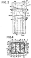
- Figure 3 is a left-side view of the embodiment from Figure 1 of the present invention.
- Figure 4 is top view of the embodiment from Figure 1 of the present invention.
- Figure 5 is an exploded perspective view of the embodiment of Figure 1 of the present invention.
- Figure 6 is a top view of the female fuse embodiment of Figure 1 of the present invention, in a preformed sheet configuration.
- Figure 7 is a front view of the preformed sheet configuration of the female fuse embodiment from Figure 6 of the present invention.
- Figure 8 is a front view of the female fuse from the female fuse assembly of Figure 1 of the present invention.
- Figure 9 is a left-side view of the female fuse from Figure 8 of the present invention.
- Figure 10 is top view of the female fuse from Figure 8 of the present invention.
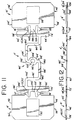
- Figure 11 is a top view of a separate female fuse embodiment of the present invention, in a preformed sheet configuration, similar to Figure 6 .
- Figure 12 is a front view of the preformed sheet configuration of the female fuse embodiment from Figure 11 of the present invention.
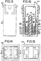
- Figure 13 is a left side view of a female fuse housing without a fuse lid.
- Figure 14 is a top view of the female fuse housing from Figure 13 .
- Figure 15 is a bottom view of the female fuse housing of Figure 13 without the female fuse being inserted therein.
- Figure 16 is a cutaway front view of the female fuse housing from Figure 13 with a further embodiment of a female fuse inserted therein, the cut away location being shown in Figure 14 .
- Figure 17 is an exploded view of the embodiment of the female fuse of Figure 16 with the female fuse housing exploded therewith.
- Figure 18 is a top view of the female fuse embodiment of Figure 16 , in a preformed sheet configuration.
- Figure 19 is a bottom view of the female fuse from Figure 18 with formed female fuse terminals.
- Figure 20 is a side view of the female fuse in Figure 19 .
- Figure 21 is a partial front view of a female fuse terminal of the female fuse from Figure 20 .
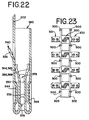
- Figure 22 is a enlarged cutaway side view of a single female fuse terminal of the female fuse in Figure 16 .
- Figure 23 is a top view of a plurality of female fuses shown during one step of the manufacturing process.
- Figures 1 through 5 show a female fuse assembly for interrupting current flowing through a circuit upon certain high current or over current conditions. Numerous occurrences can cause these types of conditions, as is well known in the art.
- the female fuse assembly is typically placed within a circuit to perform these functions.
- the circuit includes male terminals (not shown) which typically are a part of a male terminal block or fuse block (not shown) for inserting the female fuse assembly onto the male terminal block.
- Each male terminal has opposed contact surfaces for conductively connecting the female fuse assembly to the rest of the circuit, as will be further described below.
- the female fuse assembly of Figures 1 through 5 generally includes a fuse housing 2 and a female fuse 4.
- the female fuse 4 more clearly shown in Figures 6 through 10, is made from one continuous sheet of metal, preferably a copper alloy, and several manufacturing steps cuts out and otherwise forms the metal sheet into the embodiment in Figures 1 through 5 as will be described further below.
- the female fuse 4 includes a first female terminal portion 6 and a second female terminal portion 8.
- the first female terminal portion 6 includes a first face portion 10
- the second female terminal portion 8 includes a second face portion 12.
- the first and second face portions each include a first end 14, 16, a second end 18, 20, a first side 22, 24, and a second side 26, 28, respectively.
- the first side 22 of the first face portion 10 of the first female terminal portion 6 includes a first raised portion 30.
- the first raised portion 30 is formed by pressing out a rectangular shape into the second side 26 of the first face portion 10.
- the first side 24 of the second face portion 12 of the second female terminal portion 8 includes a second raised portion 32.
- the second raised portion 32 is again formed by pressing out a rectangular shape into the second side 28 of the second face portion 12.
- the first and second raised portions 30, 32 are provided on the first and second face portions 10, 12, respectively, for creating a secure engagement with the male terminals.
- the raised portions are also provided for creating a large surface area of contact between the face portions 10, 12 and the male terminals, to reduce resistance between the female terminal portions 6, 8 and the male terminals.
- the female fuse 4 further includes a first clamping arm 34 connected to the first end 14 of the first face portion 10, a first clamping arm 36 connected to the first end 16 of the second face portion 12, a second clamping arm 38 connected to the second end 18 of the first face portion 10, and a second clamping arm 40 connected to second end 20 of the second face portion 12, of the respective first and second female terminal portions 6, 8.
- the first clamping arm 34 of the first female terminal portion 6 includes a first contact edge 42
- the first clamping arm 36 of the second female terminal portion 8 includes a first contact edge 44.
- the second clamping arm 38 of the first female terminal portion 6 includes a second contact edge 46
- the second clamping arm 40 of the second female terminal portion 8 includes a second contact edge 48.
- Each of these contact edges 42, 44, 46, 48 generally face and extend toward the respective first side 22, 24 each of the respective first and second female terminal portions 6, 8, after the female fuse 4 is formed during manufacture. These contact edges 42, 44, 46, 48 are provided to engage the male terminals when the male terminals are inserted into the female terminal portions 6, 8. When the male terminals are inserted, the contact edges 42, 44, 46, 48 press against one side of the male terminals, and force the male terminals into effective contact with the respective first and second raised portions 30, 32.
- each clamping arm includes a semicircular portion formed at a proper bend, and made of a sufficient resiliency.
- the first clamping arm 34 of the first female terminal portion 6 includes a first resilient semicircular portion 50
- the first clamping arm 36 of the second female terminal portion 8 includes a first resilient semicircular portion 52.
- the second clamping arm 38 of the first female terminal portion 6 includes a second resilient semicircular portion 54
- the second clamping arm 40 of the second female terminal portion 8 includes a second resilient semicircular portion 56.
- Figures 6, 7, 11 and 12 do not show these semicircular portions 50, 52, 54, 56 as these portions are created by bending the respective clamping arms 34, 36, 38, 40 toward the first sides 22, 24 of the respective first and second faces 10, 12 of the first and second female terminal portions 6, 8.
- the female fuse 4 further includes a first bracing arm 58 connected to the first end 14 of the first face portion 10 of first female terminal portion 6, and a first bracing arm 60 connected to the first end 16 of the second face portion 12 of second female terminal portion 8.
- the female fuse 4 includes a second bracing arm 62 connected to the second end 18 of the first face portion 10 of first female terminal portion 6, and a second bracing arm 64 connected to the second end 20 of the second face portion 12 of second female terminal portion 8.
- the first bracing arm 58 of the first female terminal portion 6 includes a first bracing edge 66
- the first bracing arm 60 of the second female terminal portion 8 includes a first bracing edge 68.
- the second bracing arm 62 of the first female terminal portion 6 includes a second bracing edge 70
- the second bracing arm 64 of the second female terminal portion 8 includes a second bracing edge 72.
- the first and second bracing arms, 58, 60, 62, 64 of the respective first and second female terminal portions 6, 8 are arranged substantially perpendicular to the respective first and second face portion 10, 12 of the first and second female terminal portions 6, 8.
- the first and second bracing edges 66, 68, 70, 72 extend away from, and perpendicular to, the respective first side 22, 24 of the first and second face portion 10, 12 of the respective first and second female terminal portions 6, 8.
- the bracing arms 58, 60, 62, 64 and bracing edges 66, 68, 70, 72 are provided for bracing and stabilizing the female fuse 4 within the housing 2, as will be described in greater detail below.
- the female fuse 4 additionally includes a fuse link 80.
- the fuse link 80 includes a first terminal extension 82 and a second terminal extension 84.
- the first terminal extension 82 is connected to the first female terminal portion 6, and the second terminal extension 84 is connected to the second female terminal portion 8.
- the fuse link 80 further includes a skived region 86 connected between the first and second terminal extensions 82, 84 at a first transition point 88 and a second transition point 90.
- the skived region 86 is provided for controlling the resistance between the first and second female terminal portions, as the resistance will vary by changing the thickness of the fuse link 80. During manufacture, skiving takes place before the female fuse 4 is formed.
- the thickness is reduced in a specified area along a full sheet of metal before the sheet of metal is cut or stamped into the female fuses.
- the reduction of thickness takes place through known reduction techniques, such that the reduced area, or skived regions has a substantially uniform thickness. Skiving creates a more uniform thickness, and thus, a more reliable opening time characteristic as well as other advantages, than does casting, stamping, coining, or other reduction technique.
- the fuse link 80 also includes a fuse-blowing portion 92.
- the fuse-blowing portion 92 includes a ring 94 that has a first branch 96 and a second branch 98, which together form a pellet region 100.
- a pellet (not shown) can be placed within a pellet hole 100 or a pellet (not shown) can be placed on top of the pellet region 100, when no hole exists.
- the pellet region can be flat, or a divot can be created in the pellet region 100 to accept the pellet, without actually stamping a hole (pellet hole) within the pellet region. As described in U.S. Patent No.
- the fuse-blowing portion 92 of the fuse link 80 includes a hot spot portion or ring 94, and a fuse-blowing current-reducing material or pellet (not shown) placed within or joined with the pellet region 100.
- the material used to reduce the opening current within the pellet region 100 is preferably tin, while the overall female fuse 4 is preferably a copper alloy.
- the fuse link 80 configuration alleviates the need for any heat conduction member, and requires no additional structure for heat insulating the fuse link 80 or the female fuse 4.
- the formed fuse link 80 further includes a first terminal bend 102 and a second terminal bend 104.
- the first terminal bend 102 is positioned substantially toward the first end 14 of the first face portion 10 of the first female terminal portion 6, and the second terminal bend 104 is positioned substantially toward the second end 20 of the second face portion 12 of the second female terminal portion 8.
- the first terminal bend 102 is positioned substantially toward the second end 18 of the first face portion 10 of the first female terminal portion 6, and the second terminal bend 104 is positioned substantially toward the first end 16 of the second face portion 12 of the second female terminal portion 8.
- connection between the female fuse terminals 6, 8 and the terminal extensions 82, 84 will achieve a lengthened fuse link 80 without increasing the volume of material used, as well.
- another embodiment of the present invention includes that the connection between the first female terminal portion 6 and the first terminal extension 82 of the fuse link 80 is positioned substantially toward the first end 14 of the first face portion 10 of the first female terminal portion 6, and includes that the connection between the second female terminal portion 8 and the second terminal extension 84 of the fuse link 80 is positioned substantially toward the first end 16 of the second face portion 12 of the second female terminal portion 8.
- connection between the first female terminal portion 6 and the first terminal extension 82 of the fuse link 80 is positioned substantially toward the first end 14 of the first face portion 22 of the first female terminal portion 6, and includes that the connection between the second female terminal portion 8 and the second terminal extension 84 of the fuse link 80 is positioned substantially toward the second end 20 of the second face portion 12 of the second female terminal portion 8.
- connection between the first female terminal portion 6 and the first terminal extension 82 of the fuse link 80 is positioned substantially toward the second end 18 of the first face portion 10 of the first female terminal portion 6, and includes that the connection between the second female terminal portion 8 and the second terminal extension 84 of the fuse link 80 is positioned substantially toward the second end 20 of the second face portion 12 of the second female terminal portion 8.
- connection between the first female terminal portion 6 and the first terminal extension 82 of the fuse link 80 is positioned substantially toward the second end 22 of the first face portion 10 of the first female terminal portion 6, and includes that the connection between the second female terminal portion 8 and the second terminal extension 84 of the fuse link 80 is positioned substantially toward the first end 16 of the second face portion 12 of the second female terminal portion 8.
- the fuse link 80 is non-linear.
- Previous fuses used a fuse link which extended linearly from the first female terminal to the second female terminal when viewed from the side of the fuse (facing a face portion). No lateral curves or bends existed in these previous fuse links from a side view.
- the present fuse 4 has at least two lateral curved portions 150 which break the linearity of the fuse link 80, for increasing the length of the fuse link 80 without using any additional fuse material during manufacture.
- the housing 2 includes a main portion 106 and a cap 108.
- the fuse housing 2 is made of electrically insulating material, such as a synthetic polymer or plastic.
- the main portion 106 includes a first interior wall 110, a second interior wall 112, a third interior wall 114, and a fourth interior wall 116, a divider 118 extended between the third and the fourth interior walls 114, 116, all defining a space therein.
- the divider is provided for partially dividing the space, and includes a first interior cutout portion 120 and a second interior cutout portion 122.
- the first interior cutout portion 120 includes and is defined by a first cutout side wall 124 and a first cutout upper wall 126.
- the second interior cutout portion 122 includes and is defined by a second cutout side wall 128 and a second cutout upper wall 130.
- a flexible member can be optionally provided for assisting in holding the female fuse in place when the clamping arms 34, 36, 38, 40 face inwardly, or when the female fuse terminals 300, 301 (embodiment described below) face inwardly.
- the female fuse terminals of the various embodiments would snap securely into place through the lances, and additionally through the flexible member (not shown) disposed on the divider (central island).
- the first female terminal portion 6 includes a first lance 132.
- the first lance is defined by a first lance cutout portion 136 on the first face portion 10 of the first female terminal portion 6, and is substantially centered between the first and second ends 14, 18 of the first face portion 10 of the first female terminal portion 6.
- the first lance 132 includes a first lance edge 140.
- the second female terminal portion 8 further includes a second lance 134.
- the second lance 134 is defined by a second lance cutout portion 138 on the second face portion 12 of the second female terminal portion 8, and is substantially centered between the first and second ends 16, 20 of the second face portion 12 of the second female terminal portion 8.
- the second lance 134 also has a second lance edge 142.
- the first lance edge locks into the first interior cutout portion 120, and engages with the first cutout upper wall 126.
- the second lance edge 142 locks into the second interior cutout portion 122, and engages with the second cutout upper wall 130.
- the cap 108 of the housing 2 is preferably transparent, and locks into the main portion 108 through well known techniques.
- Figures 11 and 12 An additional specific embodiment of the present invention is shown in Figures 11 and 12 , and has generally already been described above. However, Figures 11 and 12 include reference to several common element numbers with a single prime designation instead.
- FIG. 13 through 23 A further additional embodiment of the present invention is shown is Figures 13 through 23 .
- This additional representative embodiment is also stamped from single sheet of metal as can be understood by reference to Figures 17, 18 , and 23 .
- a female fuse for interrupting a current flowing through a circuit that includes the female fuse, upon certain high current conditions.
- the female fuse is configured to accept male terminals (not shown) which are typically mounted on a male terminal block (not shown) as described above.
- the male terminals are also a part of, and are connected to, the circuit.
- the female fuse includes a fuse link 200 that has a first end 202 and a second end 203.
- the fuse link 200 includes a fuse-blowing portion between the first and second ends 202, 203 for interrupting the current flowing through the circuit.
- the female fuse also includes first and second female fuse terminals 300, 301 that are coupled to the respective first and second ends 202, 203 of the fuse link 200.
- the first and second female fuse terminals 300, 301 each includes first and second female-forming terminal plates 304, 305, 306, 307.
- Each female fuse terminal 300, 301 also includes first and second female-forming side plates 308, 309, 312, 313.
- the first and second female-forming side plates 308, 309, 312, 313 are each coupled to the first female-forming plates 304, 305 at substantially respective first and second boundaries 316, 317, 320, 321.
- the second female-forming terminal plates 306, 307 are each coupled to the respective second side plates 312, 313 at substantially third boundaries 324, 325, respectively.
- the first and the second female-forming terminal plates 304, 305, 306, 307 each include a spring portion 330, 331, 332, 333, respectively.
- the spring portions 330, 331, 332, 333 are formable into contacting springs (easily understood from Figure 22 ) for directly contacting the male terminals (not shown) when the male terminals are inserted into the female fuse terminals 300, 301, once formed.
- the first and second female-forming side plates 308, 309, 312, 313 and the first and second female-forming terminal plates 304, 305, 306, 307 are formable to generally encompass the spring portions 330, 331, 332, 333 and the male terminals, when the male terminals are inserted into the formed female fuse terminals (easily understood from Figure 16 and 17 ).
- the formed female terminals 300, 301 ( Figure 17 ) take on a box-like shape. The formation of the female fuse will be described in greater detail further below. However, the double spring configuration lowers the insertion force required to get the male terminals into the female fuse, centers the male terminals within each female terminal 300, 301.
- the female fuse shown in Figures 13 through 23 is formed from one continuous sheet of metal.
- the sheet is made from a copper alloy.
- the sheet is made from C-151, C-194, or 425.
- the first and second female fuse terminals 300, 301 also each includes first and second lances 336, 337, respectively.
- the lances 336, 337 are defined by first and second lance cutout portions 338, 339, respectively.
- the lances 336, 337 and respective cutout portions 338, 339 are substantially centered between the first and second boundaries 316, 317, 320, 321, and the first and second lances 336, 337 each have a respective lance edge 340, 341.
- OSP overstress protection
- the spring portion 330, 331, 332, 333 may overstress and permanently bend out of shape. However, with the existence of the raised portion 344, 345, 346, 347, the spring portion 330, 331, 332, 333 can only depress until the spring portion 330, 331, 332, 333 contacts the raised portion 344, 345, 346, 347, thereby providing overstress protection. This type of OSP is significant since the protection (raised portions) extends over almost the full length of the spring portions 330, 331, 332, 333.
- the raised portions 344, 345, 346, 347 can be created through the use of a die section puncher or embosser.
- the first and second boundaries 316, 317, 320, 321 are scored.
- the third and fourth boundaries 324, 325, 328, 329 are scored.
- These scoring lines shown in Figure 18 allow for ease of bending and formation of the female fuse terminals 300, 301.
- the scoring lines provide an imaginary separation (boundaries) between the several plates described above.
- boundary does not include scoring (only an imaginary line(s)), while use of the term scoring denotes actual scoring. Scoring lowers the stress on the materials during formation.
- the first and second female fuse terminals 300, 301 also each include a first and second lip 350, 351, coupled to the first female-forming side plates 308, 309, respectively, substantially at the fourth boundaries 328, 329.
- the first and second female-forming terminal plates 304, 305, 306, 307 each includes first and second notches 352, 353, 354, 355, 356, 357, 358, 359, respectively, substantially positioned on either side the respective spring portions 330, 331, 332, 333 therein. These notches 352, 353, 354, 355, 356, 357, 358, 359 provide additional spring-action to the respective spring portions 330, 331, 332, 333 associated therewith.
- the notches 352, 353, 354, 355, 356, 357, 358, 359 create the additional spring action in the spring portions 330, 331, 332, 333 by providing flexibility in the metal between the spring portions 330, 331, 332, 333 and the main body of the female forming terminal plates 304, 305, 306, 307.
- the spring action is more even with the use of the notches 352, 353, 354, 355, 356, 357, 358, 359.
- the notches 352, 353, 354, 355, 356, 357, 358, 359 also provides for ease of formation of the spring portions 330, 331, 332, 333 into the final position, as long as the notches 352, 353, 354, 355, 356, 357, 358, 359 are created before the spring portions 330, 331, 332, 333 are formed into the box-like female terminal configurations (final position).
- the notches 352, 353, 354, 355, 356, 357, 358, 359 also have a long term effect of preventing the spring portions 330, 331, 332, 333 from relaxing (bending out of shape) or prematurely breaking off (failing).
- the spring portions 330, 331, 332, 333 each include respective first and second spring legs 362, 363, 364, 365, 366, 367, 368, 369 formed on either side of a respective spring-leg forming notch 370, 371, 372, 373.
- the spring portions 330, 331, 332, 333 are bent to overlap a portion (overlap region) of the female-forming terminal plates 304, 305, 306, 307.
- the overlap region includes, at least, the raised portions 344, 345, 346, 347 thereunder.
- the first and second spring legs 362, 363, 364, 365, 366, 367, 368, 369 of the respective spring portions 330, 331, 332, 333 each include a termination edge 376 that is bent away from the overlapped portion of the female-forming terminal plates 304, 305, 306, 307.
- the female-forming side plates 308, 309, 312, 313, therefore, include viewing holes 378 for viewing into the interior of the box-like female fuse terminals 300, 301. A more thorough inspection, such as checking gap sizes, can then be performed on the spring portions 330, 331, 332, 333 and associated elements.
- the fuse link of the female fuse embodiment in Figures 13 through 23 also includes a skived region 210 between first and second transition portions 212, 213.
- the skived region 210 creates a substantially uniform thickness for the fuse link 200 between the first and second transition portions 212, 213.
- the uniform thickness enhances the performance of the fuse.
- the skiving thickness range is preferably .005 - .011 inches thick.
- the fuse link 200 further includes first and second pellet regions 214, 216 (shown as circles in the Figures).
- a pellet hole 218 can exist in each pellet region 214, 216, and tin pellets can be placed into the holes 218.
- holes 218 are not necessary in one form of the present invention, as divots (not shown) or just a flat surface can be used to support tin pellets.
- each pellet region 214, 216 will include a pellet hole 218, and both pellet holes 218 will be filled with pellets (tin). This form of the invention provides a relatively large mass on either side of where the fuse is intended to blow.
- pellet region 214 could have a pellet hole 218 and pellet therein, with the opposing pellet region 216 having no pellet hole or pellet therein (solid pellet region 216). In this form, it would not matter which pellet region 214, 216 the pellet hole 218 or pellet was on. However, only using a single pellet and pellet hole 218 in this example would require adjustments in the other slots.
- the first and second pellet regions 214, 216 are symmetrically spaced on opposing sides of a central axis that extends substantially through center of both the first female-forming terminal plates 304, 305.
- the fuse link 200 also includes first and second arc-forming strips 220, 222 that are substantially symmetrically connect the first and second pellet regions 214, 216 to one another.
- the arc shape of the these strips increase the length of the fuse link 200 without the use of any additional material during manufacture. Increasing the arc will, accordingly, increase the length of the fuse length for improved rating performance.
- the pellet regions 214, 216 and arc-forming strips 220, 222 each have an interior portion that form a bow-tie cut out portion 226.
- the bow-tie cutout portion 226 is formed from a bow-tie die section (not shown) existing within the single die that is used to create the overall fuse.
- the die includes a plurality of die sections or stamping sections which are independent of other die sections (stamping sections) within the single overall die.
- the bow-tie (slot) die section, within the overall die, is separate and distinct from the die section (stamping section) that formes the exterior shape of the female fuse.
- the bow-tie stamping section can be changed out within the overall die during manufacture to change to a different sized bow-tie stamp section in order to change the rating of the fuses being manufactured, without changing the stamping section (die section) used to form the exterior shape of the female fuse, as shown in Figure 18 .
- the cross-sectional area of the arc-forming strips 220, 222 is partially determined by the skiving, partially determined by the die section foe the exterior shape of the female fuse, and partially determined by the bow-tie die section. Controlling this cross-sectional area will control the rating in the female fuse. Controlling the sizing of the other slots will also control the rating in the female fuse. Thus, there are numerous ways to fine tune the rating of the female fuse.
- the fuse link 200 further includes first and second end slots 228, 230 substantially positioned in the respective first and second ends 202, 203.
- the end slots 228, 230 assist in controlling the rating of the fuse by providing a heat sinks on either side of the pellet regions 214, 216.
- an end-slot die section (not shown) is used to create the end slots 228, 230.
- the end-slot die section can be changed within the overall die (not shown) during manufacture, to change to a different sized end-slot die section in order to change the rating of the fuses being manufactured, without changing overall die or the die section used to form the exterior shape of the female fuse, as shown in Figure 18 .
- end slots 228, 230 and controlling the size of end slots 228, 230 assists in controlling the voltage drop across the fuse link 200, while increasing the time delay for the fuse to blow.
- These heat sinks act to pull heat away from the center of the fuse link 200 in order to increase the time delay.
- These end slots 228, 230 creating heat sinks further assist in making sure that the female fuse will blow on or between the pellet regions 214, 216.
- This configuration also provides for fast short circuit protection.
- the cross-sectional area of the arc-forming strips 220, 222 can be reduced while at the same time maintaining the same or better circuit protection features.
- One of these features includes keeping the time delay between approximately 200% and 300% of the rating current (characteristic power). Hence, this surge withstanding phase is provided while at the same time providing good short circuit protection.
- the end slots 228, 230, the pellet holes 218 (when present), and the bow-tie cut out portion 226 (or other shape) are sometimes referred to collectively as slots. These size of these slots are changed to change the rating of the female fuse. Higher rated female fuses have smaller slots, and lower rated female fuses have larger slots. Separating the die sections with this type of female fuse arrangement for the fuse link 200 provides for a more simple process because only one perimeter female fuse stamp size (for one of the die sections) is needed to create all of the various ratings for the female fuses. Only the slot stamp sizes are changed to change the rating of the female fuse.
- slot die section(s) is the only die section(s) that needs to be changed (different slots can come from different die sections). This, in turn, provides for lower labor and tooling costs.
- the fuse link 200 of the present invention can also be described as including a plurality of slots creating a fuse-blowing portion 206.
- the slots are substantially symmetrically positioned between the first and second ends 202, 203
- the slots are substantially formed from one or more die sections that are independent of the die section which formes the exterior shape of the female fuse, as is described in greater detail above.
- the method of manufacturing a plurality of the female fuses begins with a single continuous sheet of metal.
- the sheet is skived before any further steps are performed, although skiving does not have to be performed first.
- Guide bores 500 are used to guide the sheet through a main die (not shown) during the process of manufacture.
- the various elements of the female fuse are then stamped, punched, cut out or otherwise formed from different die sections located within the main die.
- first and second guide strips 502, 503 are stamped from the sheet of metal.
- the strips 502, 503 are aligned traversely from or generally perpendicular to the central axis along the length of the female fuse described above.
- the strips 502, 503 are located interior from the outermost portions of the female fuse terminals 300, 301.
- the outermost portion of the female fuse terminals coincide with the termination edge 376 of the spring portions 330, 331, 332, 333.
- the strips are aligned substantially between the ends 202, 203 of the fuse-link 200 and the female fuse terminals 300, 301.
- the fuse-links 80, 80', and 200 can be interchanged to create a variety of female fuse arrangements with the various female fuse terminal arrangements.
- a housing 400 is provided for the female fuse, that is similar to the housing in Figures 1 through 5 .
- the housing 400 includes a main portion 402 that includes a first interior wall 404, a second interior wall 406, a third interior wall 408, and a fourth interior wall 410.
- a divider 412 extends between the third 408 and the fourth 410 interior walls, and defines a space therein for receiving the female fuse.
- the divider 412 partially divides the space, and the divider 412 has an overhanging semiresilient member 414 for engaging the upper interior edges 380 of the female fuse terminals 300, 301.
Landscapes
- Engineering & Computer Science (AREA)
- Manufacturing & Machinery (AREA)
- Fuses (AREA)
- Coupling Device And Connection With Printed Circuit (AREA)
- Connector Housings Or Holding Contact Members (AREA)
- Details Of Connecting Devices For Male And Female Coupling (AREA)
- Manufacturing Of Electrical Connectors (AREA)
Claims (16)
- Fusible femelle pour interrompre un courant qui circule au travers d'un circuit incluant le fusible femelle lors de certaines conditions élevées et pour accepter des bornes mâles connectées au circuit, le fusible femelle comprenant :caractérisé en ce que :une liaison de fusible (200) comportant une première extrémité (202) et une seconde extrémité (203), la liaison de fusible incluant une partie de grillage de fusible entre les première et seconde extrémités (202, 203) pour interrompre le courant qui circule au travers du circuit ; etdes première et seconde bornes de fusible femelles (300, 301) couplées aux première et seconde extrémités respectives (202, 203) de la liaison de fusible (200), les première et seconde bornes de fusible femelles (300, 301) comportant chacune des première et seconde plaques de borne de formation d'élément femelle (304, 305, 306, 307) et des première et seconde plaques latérales de formation d'élément femelle (308, 309, 312, 313), les première et seconde plaques latérales de formation d'élément femelle (308, 309, 312, 313) étant chacune couplées aux premières plaques de borne de formation d'élément femelle (304, 305) sensiblement au niveau de première et seconde frontières respectives (316, 317, 320, 321), les secondes plaques de borne de formation d'élément femelle (306, 307) étant chacune couplées aux secondes plaques latérales respectives (312, 313) respectivement sensiblement au niveau de troisièmes frontières (324, 325),les première et seconde plaques de borne de formation d'élément femelle (304, 305, 306, 307) comportent chacune une partie de ressort (330, 331, 332, 333), les parties de ressort (330, 331, 332, 333) étant formables selon des ressorts de contact destinés à entrer en contact avec les bornes mâles lorsque les bornes mâles sont insérées dans les bornes de fusible femelles (300, 301), après formation, les première et seconde plaques latérales de formation d'élément femelle (308, 309, 312, 313) et les première et seconde plaques de borne de formation d'élément femelle (304, 305, 306, 307) étant formables de manière à englober de façon générale les parties de ressort (330, 331, 332, 333) et les bornes mâles lorsque les bornes mâles sont insérées dans les bornes de fusible femelles formées, les parties élastiques étant formées de manière à maintenir un contact entre la borne mâle et les ressorts de contact sur une longueur substantielle des ressorts de contact afin de positionner la borne mâle dans la borne de fusible femelle.
- Fusible femelle selon la revendication 1, dans lequel le fusible femelle est formé à partir d'une feuille métallique continue.
- Fusible femelle selon la revendication 1, dans lequel les première et seconde bornes de fusible femelles (300, 301) incluent respectivement chacune des première et seconde lances (336, 337) définies par des première et seconde parties en découpe de lance respectives (338, 339), sensiblement centrées entre les première et seconde frontières (316, 317, 320, 321), les première et seconde lances (336, 337) comportant chacune un bord de lance respectif (340, 341).
- Fusible femelle selon la revendication 1, dans lequel les première et seconde plaques de formation d'élément femelle (304, 305, 306, 307) incluent chacune des première et seconde parties relevées (344, 345, 346, 347) respectives.
- Fusible femelle selon la revendication 1, dans lequel les première et seconde frontières (316, 317, 320, 321) sont entaillées.
- Fusible femelle selon la revendication 1, dans lequel les première et seconde bornes de fusible femelles (300, 301) incluent chacune une quatrième frontière (328, 329) et des première et seconde lèvres (350, 351), la quatrième frontière (328, 329) étant située respectivement entre les première et seconde plaques latérales de formation d'élément femelle (308, 309) et les lèvres (350, 351).
- Fusible femelle selon la revendication 6, dans lequel les troisième et quatrième frontières (324, 325, 328, 329) sont entaillées.
- Fusible femelle selon la revendication 1, dans lequel la première plaque de borne de formation d'élément femelle (304, 305) de chaque borne de fusible femelle (300, 301) inclut des première et seconde encoches (352, 353, 354, 355) sensiblement positionnées sur l'un ou l'autre côté de la partie de ressort respective (330, 331) dedans.
- Fusible femelle selon la revendication 1, dans lequel la seconde plaque de formation d'élément femelle (306, 307) de chaque borne de fusible femelle (300, 301) inclut des première et seconde encoches (356, 357, 358, 359) sensiblement positionnées sur l'un ou l'autre côté de la partie de ressort respective (330, 331) dedans.
- Fusible femelle selon la revendication 1, dans lequel chaque partie de ressort (330, 331, 332, 333) inclut des première et seconde pattes de ressort (362, 363, 364, 365, 366, 367, 368, 369) formées sur l'un ou l'autre côté d'une encoche de formation de patte de ressort (370, 371, 372, 373) dedans.
- Fusible femelle selon la revendication 1, dans lequel les parties de ressort (330, 331, 332, 333) sont incurvées afin de chevaucher une partie des plaques de borne de formation d'élément femelle (304, 305, 306, 307) et dans lequel les première et seconde pattes de ressort (362, 363, 364, 365, 366, 367, 368, 369) incluent chacune un bord de terminaison (376) qui est éloigné par incurvation de la partie en chevauchement des plaques de borne de formation d'élément femelle (304, 305, 306, 307).
- Fusible femelle selon la revendication 1, dans lequel la première plaque latérale de formation d'élément femelle (308, 309) inclut un trou de visualisation (378).
- Fusible femelle selon la revendication 1, dans lequel la liaison de fusible (200) inclut une région progressive (210) entre des première et seconde parties de transition (212, 213), la région progressive (210) créant une épaisseur sensiblement uniforme pour la liaison de fusible (200) entre les première et seconde parties de transition (212, 213).
- Fusible femelle selon la revendication 1, dans lequel la liaison de fusible (200) inclut des première et seconde régions de pastille (214, 216), les première et seconde régions de pastille (214, 216) étant espacées de façon symétrique sur des côtés opposés d'un axe central du fusible femelle.
- Fusible femelle selon la revendication 1, dans lequel la liaison de fusible (200) inclut des première et seconde régions de pastille (214, 216), au moins l'une des première et seconde régions de pastille (214, 216) comportant une pastille qui lui est jointe.
- Fusible femelle selon la revendication 1, dans lequel la liaison de fusible (200) inclut des première et seconde régions de pastille (214, 216), et des première et seconde bandes de formation d'arc (220, 222) connectant sensiblement de façon symétrique les première et seconde régions de pastille (214, 216) l'une à l'autre.
Applications Claiming Priority (3)
| Application Number | Priority Date | Filing Date | Title |
|---|---|---|---|
| US421441 | 1982-09-21 | ||
| US08/421,441 US5581225A (en) | 1995-04-20 | 1995-04-20 | One-piece female blade fuse with housing |
| PCT/US1996/005628 WO1996033506A2 (fr) | 1995-04-20 | 1996-04-22 | Lame de fusible femelle d'une seule piece, son boitier et perfectionnements y ayant trait |
Publications (2)
| Publication Number | Publication Date |
|---|---|
| EP0821831A2 EP0821831A2 (fr) | 1998-02-04 |
| EP0821831B1 true EP0821831B1 (fr) | 1999-07-28 |
Family
ID=23670529
Family Applications (1)
| Application Number | Title | Priority Date | Filing Date |
|---|---|---|---|
| EP96913051A Expired - Lifetime EP0821831B1 (fr) | 1995-04-20 | 1996-04-22 | Lame de fusible femelle d'une seule piece, son boitier et perfectionnements y ayant trait |
Country Status (13)
| Country | Link |
|---|---|
| US (1) | US5581225A (fr) |
| EP (1) | EP0821831B1 (fr) |
| JP (2) | JPH10510667A (fr) |
| KR (1) | KR19990007917A (fr) |
| CN (1) | CN1185858A (fr) |
| AT (1) | ATE182719T1 (fr) |
| AU (1) | AU5567196A (fr) |
| BR (1) | BR9608030A (fr) |
| CA (1) | CA2218719A1 (fr) |
| DE (1) | DE69603469T2 (fr) |
| ES (1) | ES2133960T3 (fr) |
| TW (2) | TW305049B (fr) |
| WO (1) | WO1996033506A2 (fr) |
Families Citing this family (41)
| Publication number | Priority date | Publication date | Assignee | Title |
|---|---|---|---|---|
| US5883692A (en) * | 1997-10-01 | 1999-03-16 | Retsan, Inc. | Visual field measurement apparatus |
| US5886612A (en) * | 1997-10-20 | 1999-03-23 | Littelfuse, Inc. | Female fuse housing |
| US6642834B1 (en) * | 1999-03-04 | 2003-11-04 | Littelfuse, Inc. | High voltage automotive use |
| US6815841B1 (en) | 1999-11-03 | 2004-11-09 | Littelfuse, Inc. | Fuse arrangements and fuse boxes for a vehicle |
| US6407657B1 (en) * | 2000-02-03 | 2002-06-18 | Littelfuse, Inc. | Dual use fuse |
| JP4083991B2 (ja) * | 2000-02-09 | 2008-04-30 | 矢崎総業株式会社 | ヒューズユニットとその製造方法 |
| JP2001325875A (ja) * | 2000-05-18 | 2001-11-22 | Yazaki Corp | 差し込み式ヒューズ |
| USD461781S1 (en) | 2000-12-21 | 2002-08-20 | J.S.T. Mfg. Co., Ltd. | Fuse holder |
| USD462331S1 (en) | 2000-12-21 | 2002-09-03 | J.S.T. Mfg. Co., Ltd. | Fuse holder |
| US6878004B2 (en) * | 2002-03-04 | 2005-04-12 | Littelfuse, Inc. | Multi-element fuse array |
| DE112004002301T5 (de) * | 2003-11-26 | 2006-09-28 | Littelfuse, Inc., Des Plaines | Elektrische Schutzeinrichtung für ein Fahrzeug und System, das diese einsetzt |
| WO2005088665A2 (fr) | 2004-03-05 | 2005-09-22 | Littelfuse, Inc. | Fusible a profil bas pour automobile |
| CN101138062B (zh) | 2004-09-15 | 2010-08-11 | 力特保险丝有限公司 | 高电压/高电流熔断器 |
| USD555600S1 (en) * | 2004-11-30 | 2007-11-20 | Pacific Engineering Corp. | Fuse |
| USD567766S1 (en) * | 2004-11-30 | 2008-04-29 | Pacific Engineering Corp. | Fuse |
| JP4706613B2 (ja) * | 2006-03-24 | 2011-06-22 | 住友電装株式会社 | スローブローヒューズのヒューズエレメント、スローブローヒューズおよび電気接続箱 |
| KR101227739B1 (ko) * | 2006-04-26 | 2013-01-29 | 에스케이에너지 주식회사 | 기계적 물성 및 내노화 성능이 개선된 아스팔트 조성물 및그의 제조방법 |
| KR100757576B1 (ko) * | 2006-07-10 | 2007-09-10 | 현대자동차주식회사 | 2중 전원 체계의 퓨즈 구조를 갖는 차량용 정션박스 |
| JP4896630B2 (ja) * | 2006-08-28 | 2012-03-14 | 矢崎総業株式会社 | ヒューズエレメント及びヒューズエレメントの製造方法 |
| USD559203S1 (en) | 2006-11-14 | 2008-01-08 | Littelfuse, Inc. | Indicator for a fuse |
| US7983024B2 (en) | 2007-04-24 | 2011-07-19 | Littelfuse, Inc. | Fuse card system for automotive circuit protection |
| US7701321B2 (en) * | 2007-05-10 | 2010-04-20 | Delphi Technologies, Inc. | System and method for interconnecting a plurality of printed circuits |
| US7595715B2 (en) * | 2007-09-27 | 2009-09-29 | Lear Corporation | High power case fuse |
| US8077007B2 (en) | 2008-01-14 | 2011-12-13 | Littlelfuse, Inc. | Blade fuse |
| USD575746S1 (en) | 2008-01-14 | 2008-08-26 | Littelfuse, Inc. | Blade fuse and fuse element therefore |
| USD575745S1 (en) | 2008-01-14 | 2008-08-26 | Littelfuse, Inc. | Blade fuse and fuse element therefore |
| DE102008036672B3 (de) * | 2008-08-06 | 2010-03-04 | Leoni Bordnetz-Systeme Gmbh | Elektrische Schmelzsicherung |
| US8339235B2 (en) | 2008-08-06 | 2012-12-25 | Beckert James J | Housing securing apparatus for electrical components, especially fuses |
| US20100060408A1 (en) * | 2008-09-09 | 2010-03-11 | Wen-Tsung Cheng | Fuse module with indicating capability |
| US10192704B2 (en) | 2009-02-27 | 2019-01-29 | Littelfuse, Inc. | Tuning fork terminal slow blow fuse |
| JP5681389B2 (ja) * | 2009-06-10 | 2015-03-04 | 矢崎総業株式会社 | ヒュージブルリンク |
| US8366497B2 (en) * | 2009-06-17 | 2013-02-05 | Lear Corporation | Power terminal |
| US7892050B2 (en) * | 2009-06-17 | 2011-02-22 | Lear Corporation | High power fuse terminal with scalability |
| DE102011011151B4 (de) * | 2010-11-24 | 2014-12-04 | Lear Corporation | Anschlussbuchsenanordnung für eine elektrische Steckverbindung |
| US8951051B2 (en) | 2011-10-10 | 2015-02-10 | Lear Corporation | Connector having optimized tip |
| US9166322B2 (en) | 2013-02-08 | 2015-10-20 | Lear Corporation | Female electric terminal with gap between terminal beams |
| US9548553B2 (en) | 2013-03-15 | 2017-01-17 | Lear Corporation | Terminal with front end protection |
| US9190756B2 (en) | 2013-08-01 | 2015-11-17 | Lear Corporation | Electrical terminal assembly |
| DE102014011523B4 (de) | 2013-08-01 | 2025-06-26 | Lear Corporation | Elektrische anschlussanordnung |
| US9711926B2 (en) | 2013-11-19 | 2017-07-18 | Lear Corporation | Method of forming an interface for an electrical terminal |
| DE102015115464B4 (de) | 2014-09-15 | 2021-10-28 | Kromberg & Schubert Gmbh | Stromverteileranordnung |
Family Cites Families (92)
| Publication number | Priority date | Publication date | Assignee | Title |
|---|---|---|---|---|
| CA653280A (en) * | 1954-12-16 | 1962-12-04 | J. Kinkaid Robert | Terminal clip |
| US2903539A (en) * | 1955-09-26 | 1959-09-08 | Burndy Corp | Fuse receptacle |
| GB858115A (en) * | 1956-03-29 | 1961-01-04 | Lucas Industries Ltd | Electric plug and socket conductor couplings |
| US2996026A (en) * | 1956-04-05 | 1961-08-15 | Kent Mfg Corp | Method of making an electrical connector member |
| US2921287A (en) * | 1957-01-18 | 1960-01-12 | Burndy Corp | Snap fit interlocking connector |
| NL258323A (fr) * | 1959-11-27 | |||
| DE1092091B (de) * | 1960-02-23 | 1960-11-03 | Volkswagenwerk Gmbh | Steckverteiler |
| FR1312116A (fr) * | 1961-11-22 | 1962-12-14 | Connecteur électrique | |
| GB1059022A (en) * | 1963-02-08 | 1967-02-15 | English Electric Co Ltd | Improvements in and relating to electrical fuse-elements |
| DE1615002A1 (de) * | 1965-09-23 | 1970-05-27 | Curt Winemar | Flachstift-Steckkontaktverbindung |
| US3409867A (en) * | 1966-07-25 | 1968-11-05 | Efc Inc | Detachable electrical connectors |
| GB1171678A (en) * | 1967-06-06 | 1969-11-26 | Amp Inc | Electrical connector tab receptacle |
| US3524157A (en) * | 1967-08-07 | 1970-08-11 | Chase Shawmut Co | Electric current-limiting fuse |
| US3813626A (en) * | 1972-12-15 | 1974-05-28 | Robertshaw Controls Co | Fuse retainer and extractor |
| US3995929A (en) * | 1974-11-05 | 1976-12-07 | General Motors Corporation | Female terminal |
| DE2517069C2 (de) * | 1975-04-17 | 1984-04-12 | Grote & Hartmann Gmbh & Co Kg, 5600 Wuppertal | Gabelfeder sowie Gehäuse für die Gabelfeder |
| US4023264A (en) * | 1976-06-21 | 1977-05-17 | Littelfuse, Inc. | Method of making miniature plug-in fuses of different fuse ratings |
| DE2714797A1 (de) * | 1977-04-02 | 1979-02-22 | Kromberg & Schubert | Steckerartiger, elektrischer sicherungskoerper |
| US4203200A (en) * | 1977-08-01 | 1980-05-20 | Wiebe Gerald L | Method and apparatus for making an encapsulated plug-in blade fuse |
| CA1099771A (fr) * | 1977-08-19 | 1981-04-21 | Canadian General Electric Company Limited | Fusible |
| AT353882B (de) * | 1978-02-03 | 1979-12-10 | Wickmann Werke Ag | Schmelzsicherung |
| US4196409A (en) * | 1978-06-22 | 1980-04-01 | Minami International Corporation | Multiple fuse device |
| JPS6058534B2 (ja) * | 1979-06-08 | 1985-12-20 | 松下電器産業株式会社 | 磁気記録再生装置 |
| US4310719A (en) * | 1980-01-28 | 1982-01-12 | General Motors Corporation | Female terminal |
| CA1169898A (fr) * | 1980-04-28 | 1984-06-26 | Pacific Engineering Co., Ltd. | Fusible |
| US4344060A (en) * | 1980-09-19 | 1982-08-10 | Littelfuse, Inc. | Enclosed plug-in fuse assembly |
| DE3040884C2 (de) * | 1980-10-30 | 1986-09-25 | Hermann Stribel KG, 7443 Frickenhausen | Sicherungseinrichtung |
| US4319213A (en) * | 1980-12-08 | 1982-03-09 | Reid Clyde D | Electric fuse for compensating heating in the center of the fusible element |
| DE3115435A1 (de) * | 1981-04-16 | 1982-11-11 | Grote & Hartmann Gmbh & Co Kg, 5600 Wuppertal | "flachsicherung sowie verfahren zu ihrer herstellung" |
| US4349804A (en) * | 1981-05-29 | 1982-09-14 | Mcgraw-Edison | Fuse assembly for a miniature plug-in fuse |
| JPS5916054A (ja) * | 1982-07-20 | 1984-01-27 | Citizen Watch Co Ltd | マイクロ・プロセツサ |
| US4394638A (en) * | 1982-07-21 | 1983-07-19 | Essex Group, Inc. | Miniature plug-in fuse assembly and method of making a fuse element therefor |
| CA1203826A (fr) * | 1982-08-05 | 1986-04-29 | Kabushiki Kaisha T An T | Bloc compact porte-fusibles |
| JPS59178857A (ja) * | 1983-03-30 | 1984-10-11 | Toshiba Electric Equip Corp | インタ−ホン装置 |
| US4472017A (en) * | 1983-04-01 | 1984-09-18 | Essex Group, Inc. | Tab receptacle terminal |
| JPS60177527A (ja) * | 1984-02-24 | 1985-09-11 | 矢崎総業株式会社 | 多極型ヒユ−ズ素子 |
| US4580124A (en) * | 1984-08-17 | 1986-04-01 | Littelfuse, Inc. | Plug-in fuse assembly |
| US4604602A (en) * | 1984-08-17 | 1986-08-05 | Littelfuse, Inc. | Plug-in fuse assembly with stackable housing |
| JPS61166450A (ja) * | 1985-01-17 | 1986-07-28 | Fuji Seiki Seizosho:Kk | リ−ドフレ−ムの送り込み装置 |
| JPS61166449A (ja) * | 1985-01-16 | 1986-07-28 | Fuji Photo Film Co Ltd | 感光性画像記録シ−ト取出装置 |
| US4612529A (en) * | 1985-03-25 | 1986-09-16 | Cooper Industries, Inc. | Subminiature fuse |
| USRE33137E (en) * | 1985-03-25 | 1989-12-26 | Cooper Industries, Inc. | Subminiature fuse |
| US4635023A (en) * | 1985-05-22 | 1987-01-06 | Littelfuse, Inc. | Fuse assembly having a non-sagging suspended fuse link |
| US4810215A (en) * | 1985-06-06 | 1989-03-07 | Yazaki Corporation | Position compensating connector |
| JPS61294730A (ja) * | 1985-06-24 | 1986-12-25 | 住友電装株式会社 | フューズ並びにフューズを装着した電気機器 |
| US4661793A (en) * | 1985-08-15 | 1987-04-28 | Littelfuse, Inc. | Plug-in fuse assembly with specially configured fuse link |
| US4685754A (en) * | 1985-12-13 | 1987-08-11 | Amp Incorporated | Electrical tab receptacle |
| US4646052A (en) * | 1985-12-24 | 1987-02-24 | Sumitomo Wiring System, Ltd. | Slow blow fuse |
| JPS62135374U (fr) * | 1986-02-19 | 1987-08-26 | ||
| US4691981A (en) * | 1986-03-24 | 1987-09-08 | Amp Incorporated | Tab-form terminal |
| JPS62246219A (ja) * | 1986-04-18 | 1987-10-27 | 矢崎総業株式会社 | ヒユ−ズ付端子 |
| US4672352A (en) * | 1986-04-23 | 1987-06-09 | Kabushiki Kaisha T An T | Fuse assembly |
| US4670729A (en) * | 1986-06-03 | 1987-06-02 | Littelfuse, Inc. | Electrical fuse |
| DE3739051C2 (de) * | 1986-11-19 | 1995-02-23 | Yazaki Corp | Sicherung |
| JPS63250036A (ja) * | 1987-04-06 | 1988-10-17 | 矢崎総業株式会社 | ヒユ−ズ用材 |
| JPH0356995Y2 (fr) * | 1987-08-25 | 1991-12-25 | ||
| JPH0766734B2 (ja) * | 1987-09-01 | 1995-07-19 | 矢崎総業株式会社 | ヒューズの製造方法 |
| US4798545A (en) * | 1987-09-23 | 1989-01-17 | United Technologies Automotive, Inc. | Electrical terminal receptacle and electrical component housing adapted for the same |
| US4781628A (en) * | 1987-10-22 | 1988-11-01 | General Motors Corporation | Female electrical terminal |
| GB2212993B (en) * | 1987-11-30 | 1992-05-27 | Yazaki Corp | Fuse |
| JPH01241729A (ja) * | 1988-03-23 | 1989-09-26 | Yazaki Corp | ヒューズ |
| DE3909302A1 (de) * | 1988-03-23 | 1989-10-12 | Yazaki Corp | Schmelzsicherung und verfahren zur herstellung derselben |
| JP2669674B2 (ja) * | 1988-03-23 | 1997-10-29 | 矢崎総業株式会社 | ヒューズ |
| JP2667188B2 (ja) * | 1988-03-23 | 1997-10-27 | 矢崎総業株式会社 | ヒューズ及びその製造方法 |
| JPH0266828A (ja) * | 1988-08-31 | 1990-03-06 | Matsushita Refrig Co Ltd | ヒューズ |
| JPH02199735A (ja) * | 1989-01-27 | 1990-08-08 | Matsushita Refrig Co Ltd | ヒューズ |
| US5139443A (en) * | 1989-03-23 | 1992-08-18 | Littelfuse, Inc. | Housing assembly for plug-in electrical element having blade-type terminals |
| US4944697A (en) * | 1989-11-08 | 1990-07-31 | Dorman Douglas M | Automotive fuse connector |
| US4975551A (en) * | 1989-12-22 | 1990-12-04 | S & C Electric Company | Arc-extinguishing composition and articles manufactured therefrom |
| US4988969A (en) * | 1990-04-23 | 1991-01-29 | Cooper Industries, Inc. | Higher current carrying capacity 250V subminiature fuse |
| US5091712A (en) * | 1991-03-21 | 1992-02-25 | Gould Inc. | Thin film fusible element |
| US5181866A (en) * | 1991-04-03 | 1993-01-26 | Heyco Stamped Products, Inc. | High retention low insertion force electric female disconnect |
| AR246379A1 (es) * | 1991-10-09 | 1994-07-29 | Amp Inc | Fusible electrico de cuchilla. |
| JP2624593B2 (ja) * | 1991-12-12 | 1997-06-25 | 矢崎総業株式会社 | ヒューズ |
| US5147230A (en) * | 1991-12-19 | 1992-09-15 | General Motors Corporation | Two piece electrical female terminal |
| JPH05172050A (ja) * | 1991-12-21 | 1993-07-09 | Toyota Autom Loom Works Ltd | ピストン型圧縮機における冷媒ガス吸入案内機構 |
| JP2686199B2 (ja) * | 1992-01-28 | 1997-12-08 | 矢崎総業株式会社 | 雌型端子金具 |
| US5229739A (en) * | 1992-02-21 | 1993-07-20 | Littelfuse, Inc. | Automotive high current fuse |
| JP2715354B2 (ja) * | 1992-03-25 | 1998-02-18 | 矢崎総業株式会社 | ヒュージブルリンク |
| JPH0613043A (ja) * | 1992-06-29 | 1994-01-21 | Toshiba Lighting & Technol Corp | メタルハライドランプ |
| JP2571074Y2 (ja) * | 1992-07-17 | 1998-05-13 | 矢崎総業株式会社 | ヒュージブルリンク |
| JP2552868Y2 (ja) * | 1992-12-01 | 1997-10-29 | 矢崎総業株式会社 | 遅断ヒューズ |
| GB9301465D0 (en) * | 1993-01-26 | 1993-03-17 | Amp Gmbh | Electrical terminal receptacle with improved means for connecting two electrical conducting tables and a method for manufacturing it |
| US5281175A (en) * | 1993-03-30 | 1994-01-25 | General Motors Corporation | Female electrical terminal |
| JPH06290699A (ja) * | 1993-03-31 | 1994-10-18 | Yazaki Corp | ヒューズ |
| US5357234A (en) * | 1993-04-23 | 1994-10-18 | Gould Electronics Inc. | Current limiting fuse |
| US5374590A (en) * | 1993-04-28 | 1994-12-20 | International Business Machines Corporation | Fabrication and laser deletion of microfuses |
| JP2745188B2 (ja) * | 1993-06-21 | 1998-04-28 | 矢崎総業株式会社 | ヒューズ用接続端子 |
| JP2872002B2 (ja) * | 1993-06-22 | 1999-03-17 | 矢崎総業株式会社 | ヒューズ |
| US5361058A (en) * | 1993-11-02 | 1994-11-01 | Gould Electronics Inc. | Time delay fuse |
| US5346411A (en) * | 1993-12-13 | 1994-09-13 | Nikkinen Kurt D | Tap-in blade fuse |
| JP2929415B2 (ja) * | 1994-07-06 | 1999-08-03 | 矢崎総業株式会社 | ヒューズの二次ショート防止構造 |
-
1995
- 1995-04-20 US US08/421,441 patent/US5581225A/en not_active Expired - Lifetime
- 1995-04-28 TW TW084104234A patent/TW305049B/zh active
-
1996
- 1996-04-22 BR BR9608030A patent/BR9608030A/pt not_active Application Discontinuation
- 1996-04-22 AT AT96913051T patent/ATE182719T1/de not_active IP Right Cessation
- 1996-04-22 CA CA002218719A patent/CA2218719A1/fr not_active Abandoned
- 1996-04-22 KR KR1019970707440A patent/KR19990007917A/ko not_active Ceased
- 1996-04-22 WO PCT/US1996/005628 patent/WO1996033506A2/fr not_active Ceased
- 1996-04-22 AU AU55671/96A patent/AU5567196A/en not_active Abandoned
- 1996-04-22 JP JP8531996A patent/JPH10510667A/ja active Pending
- 1996-04-22 ES ES96913051T patent/ES2133960T3/es not_active Expired - Lifetime
- 1996-04-22 CN CN96194217A patent/CN1185858A/zh active Pending
- 1996-04-22 EP EP96913051A patent/EP0821831B1/fr not_active Expired - Lifetime
- 1996-04-22 DE DE69603469T patent/DE69603469T2/de not_active Expired - Lifetime
- 1996-06-11 TW TW085107026A patent/TW314636B/zh active
-
2003
- 2003-09-10 JP JP2003318935A patent/JP2004006425A/ja active Pending
Also Published As
| Publication number | Publication date |
|---|---|
| TW305049B (fr) | 1997-05-11 |
| ES2133960T3 (es) | 1999-09-16 |
| CN1185858A (zh) | 1998-06-24 |
| BR9608030A (pt) | 1999-05-04 |
| TW314636B (en) | 1997-09-01 |
| JPH10510667A (ja) | 1998-10-13 |
| EP0821831A2 (fr) | 1998-02-04 |
| WO1996033506A3 (fr) | 1997-01-16 |
| CA2218719A1 (fr) | 1996-10-24 |
| MX9708059A (es) | 1998-07-31 |
| ATE182719T1 (de) | 1999-08-15 |
| DE69603469D1 (de) | 1999-09-02 |
| DE69603469T2 (de) | 2000-02-17 |
| AU5567196A (en) | 1996-11-07 |
| JP2004006425A (ja) | 2004-01-08 |
| WO1996033506A2 (fr) | 1996-10-24 |
| KR19990007917A (ko) | 1999-01-25 |
| US5581225A (en) | 1996-12-03 |
Similar Documents
| Publication | Publication Date | Title |
|---|---|---|
| EP0821831B1 (fr) | Lame de fusible femelle d'une seule piece, son boitier et perfectionnements y ayant trait | |
| US5929740A (en) | One-piece female blade fuse with housing and improvements thereof | |
| CA1175871A (fr) | Element fusible pour fusible miniature embrochable | |
| JP2745188B2 (ja) | ヒューズ用接続端子 | |
| US6633222B2 (en) | Battery breaker | |
| US5841338A (en) | Fuse combination, method of making the same, and fuse circuit including the same | |
| US20010043139A1 (en) | Push-in type fuse | |
| JPH0644446B2 (ja) | 差込み式ヒュ−ズ装置 | |
| AU3725693A (en) | Automotive high current fuse | |
| JPH043381Y2 (fr) | ||
| US5818320A (en) | Fuse assembly with removable fusible element | |
| CN1957434B (zh) | 汽车用叶片式熔断器 | |
| US4056884A (en) | Method of making a miniature plug-in fuse | |
| EP0767479A2 (fr) | Elément fusible pour fusible lent | |
| US5745023A (en) | Fuse element having low melting point curved surface metal and clamping pieces with projections | |
| CA1074371A (fr) | Fusible comprenant une bande fusible laminee fixee a un support isolant | |
| US4040175A (en) | Method of making a miniature plug-in fuse with fragile fuse link | |
| US7317375B2 (en) | Adjustable safety switch | |
| CA2266476A1 (fr) | Prise electrique a mecanisme de retenue variable de la fiche male | |
| TW202133207A (zh) | 限流保險絲 | |
| IT8224338A1 (it) | Ricettacolo di contatto elettrico | |
| JPH10199395A (ja) | 多極型ヒューズ素子およびこの素子を使用した多極型ヒューズ | |
| JP7845613B2 (ja) | 電気ヒューズ | |
| EP0385202A1 (fr) | Disjoncteur à bilame enfermé | |
| EP1098405B1 (fr) | Pièce d'écartement réglable pour les contacts à machoires d'une base recevant des disjoncteurs |
Legal Events
| Date | Code | Title | Description |
|---|---|---|---|
| PUAI | Public reference made under article 153(3) epc to a published international application that has entered the european phase |
Free format text: ORIGINAL CODE: 0009012 |
|
| 17P | Request for examination filed |
Effective date: 19971107 |
|
| AK | Designated contracting states |
Kind code of ref document: A2 Designated state(s): AT BE CH DE DK ES FI FR GB GR IE IT LI LU MC NL PT SE |
|
| 17Q | First examination report despatched |
Effective date: 19980204 |
|
| GRAG | Despatch of communication of intention to grant |
Free format text: ORIGINAL CODE: EPIDOS AGRA |
|
| GRAG | Despatch of communication of intention to grant |
Free format text: ORIGINAL CODE: EPIDOS AGRA |
|
| GRAH | Despatch of communication of intention to grant a patent |
Free format text: ORIGINAL CODE: EPIDOS IGRA |
|
| GRAH | Despatch of communication of intention to grant a patent |
Free format text: ORIGINAL CODE: EPIDOS IGRA |
|
| GRAA | (expected) grant |
Free format text: ORIGINAL CODE: 0009210 |
|
| AK | Designated contracting states |
Kind code of ref document: B1 Designated state(s): AT BE CH DE DK ES FI FR GB GR IE IT LI LU MC NL PT SE |
|
| PG25 | Lapsed in a contracting state [announced via postgrant information from national office to epo] |
Ref country code: SE Free format text: THE PATENT HAS BEEN ANNULLED BY A DECISION OF A NATIONAL AUTHORITY Effective date: 19990728 Ref country code: NL Free format text: LAPSE BECAUSE OF FAILURE TO SUBMIT A TRANSLATION OF THE DESCRIPTION OR TO PAY THE FEE WITHIN THE PRESCRIBED TIME-LIMIT Effective date: 19990728 Ref country code: LI Free format text: LAPSE BECAUSE OF FAILURE TO SUBMIT A TRANSLATION OF THE DESCRIPTION OR TO PAY THE FEE WITHIN THE PRESCRIBED TIME-LIMIT Effective date: 19990728 Ref country code: GR Free format text: LAPSE BECAUSE OF NON-PAYMENT OF DUE FEES Effective date: 19990728 Ref country code: FI Free format text: LAPSE BECAUSE OF NON-PAYMENT OF DUE FEES Effective date: 19990728 Ref country code: CH Free format text: LAPSE BECAUSE OF FAILURE TO SUBMIT A TRANSLATION OF THE DESCRIPTION OR TO PAY THE FEE WITHIN THE PRESCRIBED TIME-LIMIT Effective date: 19990728 Ref country code: BE Free format text: LAPSE BECAUSE OF FAILURE TO SUBMIT A TRANSLATION OF THE DESCRIPTION OR TO PAY THE FEE WITHIN THE PRESCRIBED TIME-LIMIT Effective date: 19990728 Ref country code: AT Free format text: LAPSE BECAUSE OF FAILURE TO SUBMIT A TRANSLATION OF THE DESCRIPTION OR TO PAY THE FEE WITHIN THE PRESCRIBED TIME-LIMIT Effective date: 19990728 |
|
| REF | Corresponds to: |
Ref document number: 182719 Country of ref document: AT Date of ref document: 19990815 Kind code of ref document: T |
|
| REG | Reference to a national code |
Ref country code: CH Ref legal event code: EP |
|
| REF | Corresponds to: |
Ref document number: 69603469 Country of ref document: DE Date of ref document: 19990902 |
|
| REG | Reference to a national code |
Ref country code: ES Ref legal event code: FG2A Ref document number: 2133960 Country of ref document: ES Kind code of ref document: T3 |
|
| REG | Reference to a national code |
Ref country code: IE Ref legal event code: FG4D |
|
| PG25 | Lapsed in a contracting state [announced via postgrant information from national office to epo] |
Ref country code: PT Free format text: LAPSE BECAUSE OF FAILURE TO SUBMIT A TRANSLATION OF THE DESCRIPTION OR TO PAY THE FEE WITHIN THE PRESCRIBED TIME-LIMIT Effective date: 19991028 Ref country code: DK Free format text: LAPSE BECAUSE OF FAILURE TO SUBMIT A TRANSLATION OF THE DESCRIPTION OR TO PAY THE FEE WITHIN THE PRESCRIBED TIME-LIMIT Effective date: 19991028 |
|
| ET | Fr: translation filed | ||
| NLV1 | Nl: lapsed or annulled due to failure to fulfill the requirements of art. 29p and 29m of the patents act | ||
| REG | Reference to a national code |
Ref country code: CH Ref legal event code: PL |
|
| PGFP | Annual fee paid to national office [announced via postgrant information from national office to epo] |
Ref country code: GB Payment date: 20000321 Year of fee payment: 5 |
|
| PGFP | Annual fee paid to national office [announced via postgrant information from national office to epo] |
Ref country code: ES Payment date: 20000407 Year of fee payment: 5 |
|
| PG25 | Lapsed in a contracting state [announced via postgrant information from national office to epo] |
Ref country code: LU Free format text: LAPSE BECAUSE OF NON-PAYMENT OF DUE FEES Effective date: 20000422 Ref country code: IE Free format text: LAPSE BECAUSE OF NON-PAYMENT OF DUE FEES Effective date: 20000422 |
|
| PLBE | No opposition filed within time limit |
Free format text: ORIGINAL CODE: 0009261 |
|
| STAA | Information on the status of an ep patent application or granted ep patent |
Free format text: STATUS: NO OPPOSITION FILED WITHIN TIME LIMIT |
|
| 26N | No opposition filed | ||
| PG25 | Lapsed in a contracting state [announced via postgrant information from national office to epo] |
Ref country code: MC Free format text: LAPSE BECAUSE OF NON-PAYMENT OF DUE FEES Effective date: 20001031 |
|
| REG | Reference to a national code |
Ref country code: IE Ref legal event code: MM4A |
|
| PG25 | Lapsed in a contracting state [announced via postgrant information from national office to epo] |
Ref country code: GB Free format text: LAPSE BECAUSE OF NON-PAYMENT OF DUE FEES Effective date: 20010422 |
|
| PG25 | Lapsed in a contracting state [announced via postgrant information from national office to epo] |
Ref country code: ES Free format text: LAPSE BECAUSE OF NON-PAYMENT OF DUE FEES Effective date: 20010423 |
|
| GBPC | Gb: european patent ceased through non-payment of renewal fee |
Effective date: 20010422 |
|
| REG | Reference to a national code |
Ref country code: ES Ref legal event code: FD2A Effective date: 20030203 |
|
| PGFP | Annual fee paid to national office [announced via postgrant information from national office to epo] |
Ref country code: FR Payment date: 20031013 Year of fee payment: 8 |
|
| PG25 | Lapsed in a contracting state [announced via postgrant information from national office to epo] |
Ref country code: FR Free format text: LAPSE BECAUSE OF NON-PAYMENT OF DUE FEES Effective date: 20041231 |
|
| REG | Reference to a national code |
Ref country code: FR Ref legal event code: ST |
|
| REG | Reference to a national code |
Ref country code: FR Ref legal event code: RN |
|
| PG25 | Lapsed in a contracting state [announced via postgrant information from national office to epo] |
Ref country code: IT Free format text: LAPSE BECAUSE OF NON-PAYMENT OF DUE FEES;WARNING: LAPSES OF ITALIAN PATENTS WITH EFFECTIVE DATE BEFORE 2007 MAY HAVE OCCURRED AT ANY TIME BEFORE 2007. THE CORRECT EFFECTIVE DATE MAY BE DIFFERENT FROM THE ONE RECORDED. Effective date: 20050422 |
|
| REG | Reference to a national code |
Ref country code: FR Ref legal event code: FC |
|
| PGFP | Annual fee paid to national office [announced via postgrant information from national office to epo] |
Ref country code: DE Payment date: 20150429 Year of fee payment: 20 |
|
| REG | Reference to a national code |
Ref country code: DE Ref legal event code: R071 Ref document number: 69603469 Country of ref document: DE |