EP0822071A2 - Ansteuerungsverfahren für einen Tintenstrahldruckkopf - Google Patents
Ansteuerungsverfahren für einen Tintenstrahldruckkopf Download PDFInfo
- Publication number
- EP0822071A2 EP0822071A2 EP97203078A EP97203078A EP0822071A2 EP 0822071 A2 EP0822071 A2 EP 0822071A2 EP 97203078 A EP97203078 A EP 97203078A EP 97203078 A EP97203078 A EP 97203078A EP 0822071 A2 EP0822071 A2 EP 0822071A2
- Authority
- EP
- European Patent Office
- Prior art keywords
- image signal
- recording
- heat generating
- accordance
- ink
- Prior art date
- Legal status (The legal status is an assumption and is not a legal conclusion. Google has not performed a legal analysis and makes no representation as to the accuracy of the status listed.)
- Granted
Links
Images





Classifications
-
- B—PERFORMING OPERATIONS; TRANSPORTING
- B41—PRINTING; LINING MACHINES; TYPEWRITERS; STAMPS
- B41J—TYPEWRITERS; SELECTIVE PRINTING MECHANISMS, i.e. MECHANISMS PRINTING OTHERWISE THAN FROM A FORME; CORRECTION OF TYPOGRAPHICAL ERRORS
- B41J2/00—Typewriters or selective printing mechanisms characterised by the printing or marking process for which they are designed
- B41J2/005—Typewriters or selective printing mechanisms characterised by the printing or marking process for which they are designed characterised by bringing liquid or particles selectively into contact with a printing material
- B41J2/01—Ink jet
- B41J2/015—Ink jet characterised by the jet generation process
- B41J2/04—Ink jet characterised by the jet generation process generating single droplets or particles on demand
- B41J2/045—Ink jet characterised by the jet generation process generating single droplets or particles on demand by pressure, e.g. electromechanical transducers
- B41J2/04501—Control methods or devices therefor, e.g. driver circuits, control circuits
- B41J2/04508—Control methods or devices therefor, e.g. driver circuits, control circuits aiming at correcting other parameters
-
- B—PERFORMING OPERATIONS; TRANSPORTING
- B41—PRINTING; LINING MACHINES; TYPEWRITERS; STAMPS
- B41J—TYPEWRITERS; SELECTIVE PRINTING MECHANISMS, i.e. MECHANISMS PRINTING OTHERWISE THAN FROM A FORME; CORRECTION OF TYPOGRAPHICAL ERRORS
- B41J2/00—Typewriters or selective printing mechanisms characterised by the printing or marking process for which they are designed
- B41J2/005—Typewriters or selective printing mechanisms characterised by the printing or marking process for which they are designed characterised by bringing liquid or particles selectively into contact with a printing material
- B41J2/01—Ink jet
- B41J2/015—Ink jet characterised by the jet generation process
- B41J2/04—Ink jet characterised by the jet generation process generating single droplets or particles on demand
- B41J2/045—Ink jet characterised by the jet generation process generating single droplets or particles on demand by pressure, e.g. electromechanical transducers
- B41J2/04501—Control methods or devices therefor, e.g. driver circuits, control circuits
- B41J2/04528—Control methods or devices therefor, e.g. driver circuits, control circuits aiming at warming up the head
-
- B—PERFORMING OPERATIONS; TRANSPORTING
- B41—PRINTING; LINING MACHINES; TYPEWRITERS; STAMPS
- B41J—TYPEWRITERS; SELECTIVE PRINTING MECHANISMS, i.e. MECHANISMS PRINTING OTHERWISE THAN FROM A FORME; CORRECTION OF TYPOGRAPHICAL ERRORS
- B41J2/00—Typewriters or selective printing mechanisms characterised by the printing or marking process for which they are designed
- B41J2/005—Typewriters or selective printing mechanisms characterised by the printing or marking process for which they are designed characterised by bringing liquid or particles selectively into contact with a printing material
- B41J2/01—Ink jet
- B41J2/015—Ink jet characterised by the jet generation process
- B41J2/04—Ink jet characterised by the jet generation process generating single droplets or particles on demand
- B41J2/045—Ink jet characterised by the jet generation process generating single droplets or particles on demand by pressure, e.g. electromechanical transducers
- B41J2/04501—Control methods or devices therefor, e.g. driver circuits, control circuits
- B41J2/04533—Control methods or devices therefor, e.g. driver circuits, control circuits controlling a head having several actuators per chamber
-
- B—PERFORMING OPERATIONS; TRANSPORTING
- B41—PRINTING; LINING MACHINES; TYPEWRITERS; STAMPS
- B41J—TYPEWRITERS; SELECTIVE PRINTING MECHANISMS, i.e. MECHANISMS PRINTING OTHERWISE THAN FROM A FORME; CORRECTION OF TYPOGRAPHICAL ERRORS
- B41J2/00—Typewriters or selective printing mechanisms characterised by the printing or marking process for which they are designed
- B41J2/005—Typewriters or selective printing mechanisms characterised by the printing or marking process for which they are designed characterised by bringing liquid or particles selectively into contact with a printing material
- B41J2/01—Ink jet
- B41J2/015—Ink jet characterised by the jet generation process
- B41J2/04—Ink jet characterised by the jet generation process generating single droplets or particles on demand
- B41J2/045—Ink jet characterised by the jet generation process generating single droplets or particles on demand by pressure, e.g. electromechanical transducers
- B41J2/04501—Control methods or devices therefor, e.g. driver circuits, control circuits
- B41J2/04541—Specific driving circuit
-
- B—PERFORMING OPERATIONS; TRANSPORTING
- B41—PRINTING; LINING MACHINES; TYPEWRITERS; STAMPS
- B41J—TYPEWRITERS; SELECTIVE PRINTING MECHANISMS, i.e. MECHANISMS PRINTING OTHERWISE THAN FROM A FORME; CORRECTION OF TYPOGRAPHICAL ERRORS
- B41J2/00—Typewriters or selective printing mechanisms characterised by the printing or marking process for which they are designed
- B41J2/005—Typewriters or selective printing mechanisms characterised by the printing or marking process for which they are designed characterised by bringing liquid or particles selectively into contact with a printing material
- B41J2/01—Ink jet
- B41J2/015—Ink jet characterised by the jet generation process
- B41J2/04—Ink jet characterised by the jet generation process generating single droplets or particles on demand
- B41J2/045—Ink jet characterised by the jet generation process generating single droplets or particles on demand by pressure, e.g. electromechanical transducers
- B41J2/04501—Control methods or devices therefor, e.g. driver circuits, control circuits
- B41J2/04543—Block driving
-
- B—PERFORMING OPERATIONS; TRANSPORTING
- B41—PRINTING; LINING MACHINES; TYPEWRITERS; STAMPS
- B41J—TYPEWRITERS; SELECTIVE PRINTING MECHANISMS, i.e. MECHANISMS PRINTING OTHERWISE THAN FROM A FORME; CORRECTION OF TYPOGRAPHICAL ERRORS
- B41J2/00—Typewriters or selective printing mechanisms characterised by the printing or marking process for which they are designed
- B41J2/005—Typewriters or selective printing mechanisms characterised by the printing or marking process for which they are designed characterised by bringing liquid or particles selectively into contact with a printing material
- B41J2/01—Ink jet
- B41J2/015—Ink jet characterised by the jet generation process
- B41J2/04—Ink jet characterised by the jet generation process generating single droplets or particles on demand
- B41J2/045—Ink jet characterised by the jet generation process generating single droplets or particles on demand by pressure, e.g. electromechanical transducers
- B41J2/04501—Control methods or devices therefor, e.g. driver circuits, control circuits
- B41J2/04563—Control methods or devices therefor, e.g. driver circuits, control circuits detecting head temperature; Ink temperature
-
- B—PERFORMING OPERATIONS; TRANSPORTING
- B41—PRINTING; LINING MACHINES; TYPEWRITERS; STAMPS
- B41J—TYPEWRITERS; SELECTIVE PRINTING MECHANISMS, i.e. MECHANISMS PRINTING OTHERWISE THAN FROM A FORME; CORRECTION OF TYPOGRAPHICAL ERRORS
- B41J2/00—Typewriters or selective printing mechanisms characterised by the printing or marking process for which they are designed
- B41J2/005—Typewriters or selective printing mechanisms characterised by the printing or marking process for which they are designed characterised by bringing liquid or particles selectively into contact with a printing material
- B41J2/01—Ink jet
- B41J2/015—Ink jet characterised by the jet generation process
- B41J2/04—Ink jet characterised by the jet generation process generating single droplets or particles on demand
- B41J2/045—Ink jet characterised by the jet generation process generating single droplets or particles on demand by pressure, e.g. electromechanical transducers
- B41J2/04501—Control methods or devices therefor, e.g. driver circuits, control circuits
- B41J2/0458—Control methods or devices therefor, e.g. driver circuits, control circuits controlling heads based on heating elements forming bubbles
-
- B—PERFORMING OPERATIONS; TRANSPORTING
- B41—PRINTING; LINING MACHINES; TYPEWRITERS; STAMPS
- B41J—TYPEWRITERS; SELECTIVE PRINTING MECHANISMS, i.e. MECHANISMS PRINTING OTHERWISE THAN FROM A FORME; CORRECTION OF TYPOGRAPHICAL ERRORS
- B41J2/00—Typewriters or selective printing mechanisms characterised by the printing or marking process for which they are designed
- B41J2/005—Typewriters or selective printing mechanisms characterised by the printing or marking process for which they are designed characterised by bringing liquid or particles selectively into contact with a printing material
- B41J2/01—Ink jet
- B41J2/015—Ink jet characterised by the jet generation process
- B41J2/04—Ink jet characterised by the jet generation process generating single droplets or particles on demand
- B41J2/045—Ink jet characterised by the jet generation process generating single droplets or particles on demand by pressure, e.g. electromechanical transducers
- B41J2/04501—Control methods or devices therefor, e.g. driver circuits, control circuits
- B41J2/04588—Control methods or devices therefor, e.g. driver circuits, control circuits using a specific waveform
-
- B—PERFORMING OPERATIONS; TRANSPORTING
- B41—PRINTING; LINING MACHINES; TYPEWRITERS; STAMPS
- B41J—TYPEWRITERS; SELECTIVE PRINTING MECHANISMS, i.e. MECHANISMS PRINTING OTHERWISE THAN FROM A FORME; CORRECTION OF TYPOGRAPHICAL ERRORS
- B41J2/00—Typewriters or selective printing mechanisms characterised by the printing or marking process for which they are designed
- B41J2/005—Typewriters or selective printing mechanisms characterised by the printing or marking process for which they are designed characterised by bringing liquid or particles selectively into contact with a printing material
- B41J2/01—Ink jet
- B41J2/015—Ink jet characterised by the jet generation process
- B41J2/04—Ink jet characterised by the jet generation process generating single droplets or particles on demand
- B41J2/045—Ink jet characterised by the jet generation process generating single droplets or particles on demand by pressure, e.g. electromechanical transducers
- B41J2/04501—Control methods or devices therefor, e.g. driver circuits, control circuits
- B41J2/0459—Height of the driving signal being adjusted
-
- B—PERFORMING OPERATIONS; TRANSPORTING
- B41—PRINTING; LINING MACHINES; TYPEWRITERS; STAMPS
- B41J—TYPEWRITERS; SELECTIVE PRINTING MECHANISMS, i.e. MECHANISMS PRINTING OTHERWISE THAN FROM A FORME; CORRECTION OF TYPOGRAPHICAL ERRORS
- B41J2/00—Typewriters or selective printing mechanisms characterised by the printing or marking process for which they are designed
- B41J2/005—Typewriters or selective printing mechanisms characterised by the printing or marking process for which they are designed characterised by bringing liquid or particles selectively into contact with a printing material
- B41J2/01—Ink jet
- B41J2/015—Ink jet characterised by the jet generation process
- B41J2/04—Ink jet characterised by the jet generation process generating single droplets or particles on demand
- B41J2/045—Ink jet characterised by the jet generation process generating single droplets or particles on demand by pressure, e.g. electromechanical transducers
- B41J2/04501—Control methods or devices therefor, e.g. driver circuits, control circuits
- B41J2/04591—Width of the driving signal being adjusted
-
- B—PERFORMING OPERATIONS; TRANSPORTING
- B41—PRINTING; LINING MACHINES; TYPEWRITERS; STAMPS
- B41J—TYPEWRITERS; SELECTIVE PRINTING MECHANISMS, i.e. MECHANISMS PRINTING OTHERWISE THAN FROM A FORME; CORRECTION OF TYPOGRAPHICAL ERRORS
- B41J2/00—Typewriters or selective printing mechanisms characterised by the printing or marking process for which they are designed
- B41J2/005—Typewriters or selective printing mechanisms characterised by the printing or marking process for which they are designed characterised by bringing liquid or particles selectively into contact with a printing material
- B41J2/01—Ink jet
- B41J2/015—Ink jet characterised by the jet generation process
- B41J2/04—Ink jet characterised by the jet generation process generating single droplets or particles on demand
- B41J2/045—Ink jet characterised by the jet generation process generating single droplets or particles on demand by pressure, e.g. electromechanical transducers
- B41J2/04501—Control methods or devices therefor, e.g. driver circuits, control circuits
- B41J2/04596—Non-ejecting pulses
-
- B—PERFORMING OPERATIONS; TRANSPORTING
- B41—PRINTING; LINING MACHINES; TYPEWRITERS; STAMPS
- B41J—TYPEWRITERS; SELECTIVE PRINTING MECHANISMS, i.e. MECHANISMS PRINTING OTHERWISE THAN FROM A FORME; CORRECTION OF TYPOGRAPHICAL ERRORS
- B41J2/00—Typewriters or selective printing mechanisms characterised by the printing or marking process for which they are designed
- B41J2/005—Typewriters or selective printing mechanisms characterised by the printing or marking process for which they are designed characterised by bringing liquid or particles selectively into contact with a printing material
- B41J2/01—Ink jet
- B41J2/07—Ink jet characterised by jet control
- B41J2/072—Ink jet characterised by jet control by thermal compensation
-
- B—PERFORMING OPERATIONS; TRANSPORTING
- B41—PRINTING; LINING MACHINES; TYPEWRITERS; STAMPS
- B41J—TYPEWRITERS; SELECTIVE PRINTING MECHANISMS, i.e. MECHANISMS PRINTING OTHERWISE THAN FROM A FORME; CORRECTION OF TYPOGRAPHICAL ERRORS
- B41J2/00—Typewriters or selective printing mechanisms characterised by the printing or marking process for which they are designed
- B41J2/315—Typewriters or selective printing mechanisms characterised by the printing or marking process for which they are designed characterised by selective application of heat to a heat sensitive printing or impression-transfer material
- B41J2/32—Typewriters or selective printing mechanisms characterised by the printing or marking process for which they are designed characterised by selective application of heat to a heat sensitive printing or impression-transfer material using thermal heads
- B41J2/35—Typewriters or selective printing mechanisms characterised by the printing or marking process for which they are designed characterised by selective application of heat to a heat sensitive printing or impression-transfer material using thermal heads providing current or voltage to the thermal head
- B41J2/355—Control circuits for heating-element selection
- B41J2/3551—Block driving
-
- B—PERFORMING OPERATIONS; TRANSPORTING
- B41—PRINTING; LINING MACHINES; TYPEWRITERS; STAMPS
- B41J—TYPEWRITERS; SELECTIVE PRINTING MECHANISMS, i.e. MECHANISMS PRINTING OTHERWISE THAN FROM A FORME; CORRECTION OF TYPOGRAPHICAL ERRORS
- B41J2/00—Typewriters or selective printing mechanisms characterised by the printing or marking process for which they are designed
- B41J2/315—Typewriters or selective printing mechanisms characterised by the printing or marking process for which they are designed characterised by selective application of heat to a heat sensitive printing or impression-transfer material
- B41J2/32—Typewriters or selective printing mechanisms characterised by the printing or marking process for which they are designed characterised by selective application of heat to a heat sensitive printing or impression-transfer material using thermal heads
- B41J2/35—Typewriters or selective printing mechanisms characterised by the printing or marking process for which they are designed characterised by selective application of heat to a heat sensitive printing or impression-transfer material using thermal heads providing current or voltage to the thermal head
- B41J2/355—Control circuits for heating-element selection
- B41J2/36—Print density control
- B41J2/365—Print density control by compensation for variation in temperature
Definitions
- the present invention relates to a driving method for an ink jet head for recording onto a recording medium by discharging the ink in accordance with image signals.
- a recording apparatus such as printer, copying machine or facsimile terminal equipment is constituted to record an image composed of dot patterns onto a recording medium such as paper or plastic thin film.
- Recording apparatuses can be classified into those of ink jet, wire dot, thermal and laser beam type, based on the recording method, in which the ink jet method (ink jet recording apparatus) is constituted to record by discharging fine ink (recording liquid) droplets through discharge ports of ink jet head to deposit them onto recording medium.
- the ink jet method ink jet recording apparatus
- the ink jet method is constituted to record by discharging fine ink (recording liquid) droplets through discharge ports of ink jet head to deposit them onto recording medium.
- the ink jet head (recording head) mounted on the ink jet recording apparatus uses either electro-thermal converters or electromechanical transducers as the discharge energy generating element.
- the on-demand type is widely used because it can easily implement the multi-nozzle, and no operation for waste ink is necessary.
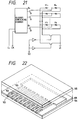
- Fig. 22 is a typical exploded perspective view exemplifying a typical structure of an ink jet head using the heat energy.
- 101 is a silicone (Si) substrate
- 102 are a plurality of heat generating elements for discharge (electro-thermal converters) incorporated into the substrate
- 103 is a discharge port provided corresponding to each of the heat generating elements
- 104 is a liquid channel in which each of the heat generating elements is disposed
- 105 is a ceiling plate of glass which forms a ceiling of liquid channels 104
- 106 is a support plate made of Al to which the substrate 101 is attached by using adhesive.
- the ink is in contact directly with the heat generating elements 102, or with the support plate 106 via a thin protecting film of less than several ⁇ m.
- the arrangement density of the heat generating elements 102 may depend on the recording density, but is normally about 3 to 30/mm.
- pulsed electrical energy for driving is given to each of the heat generating elements 102 in accordance with image signals of several hundreds to several millions times per second.
- each heat generating element is heated, so that air bubbles are produced in the ink within the liquid channels 104.
- the ink is discharged through the discharge ports 103 to record images onto a record surface of recording medium, not shown.
- the heat generated by the heat generating elements 102 is not completely used up, so that residual heat is accumulated.
- the amount of heat energy generated by the ink jet head is varied with the number of image signals.
- the ink jet head having a plurality of heat generating elements is likely to have uneven distribution of generated heat in a direction of array of heat generating elements, due to a certain pattern of image signals.
- the heat accumulation, variation of heating value, and uneven distribution of heating value may cause some fluctuation or ununiformity of head temperature.
- the ink jet head by the use of the heat energy may cause the increase of image density. Accordingly, the heat accumulation, variation of temperature and uneven distribution of temperature for the head may appear as the fluctuation or irregularities of image density on image.
- the external temperature will also vary the whole image density up and down.
- U.S. Patent No. 4,719,472 has disclosed a head constitution in which a temperature sensor and a heater for heating are disposed within an ink reservoir.
- Japanese Laid-Open Patent Application No. 1-133748 has disclosed a method for controlling so as not to produce the temperature gradient of recording liquid by turning on/off heating means based on the temperature information from both a temperature sensor provided within a common liquid chamber and a temperature sensor provided at an inlet portion of common liquid chamber.
- Japanese Laid-Open Patent Application No. 63-116857 has disclosed a head having temperature detecting means provided within each of liquid channels, apart from heat generating elements for discharging the ink.
- Japanese Patent Application No. 1-184416 has disclosed a substrate incorporating a temperature sensor for detecting the temperature of substrate. Further, the same application has disclosed an ink jet head in which heating means for heating the head is provided, in addition to heat generating elements for discharge, and control means is provided for driving optionally the heat generating elements so as to generate the heat enough not to cause the discharge of ink, as well as compensating for the temperature distribution of the head with such heating.
- Japanese Laid-Open Patent Application No. 61-146550 has proposed heating control means for heating the ink by setting an electrical signal in a range where the ink can not be discharged
- Japanese Laid-Open Patent Application No. 61-189948 has proposed preliminary energizing means for head driving with which a predetermined bias voltage is applied to heat generating elements
- Japanese Laid-Open Patent Application No. 62-220345 has proposed a constitution in which heating means for generating the heat energy not forming ink droplets is provided on heat energy generating means for discharging the ink
- Japanese Laid-Open Patent Application No. 63-134249 has proposed a constitution in which second heat energy generating means for controlling the ink temperature is provided in the vicinity of heat energy generating element for discharging the ink.
- the ink jet head using the heat energy could detect the temperature in the vicinity of heat generating element by using the variation of resistance value caused by the temperature in a temperature detection layer between the heat generating element 102 and the ink.
- the temperature of support plate 106 was detected by a thermistor.
- the heat generating element 102 was one in which head generating elements were arranged in about fourteen elements per 1 mm on a Si substrate of about 8 mm x 10 mm, and an electrical pulse of about 50 ⁇ j for each time was applied.
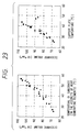
- Fig. 23 is a graph showing the relation between the temperature and the discharge volume when the frequency for giving the electrical pulse and the head temperature are changed.
- the temperature elevation curve was measured in the vicinity of heat generating element immediately after start of repetitive application of electrical pulses with its frequency fixed at about 2 kHz.
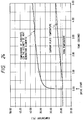
- Fig. 24 is a graph showing a result of measuring the temperature in the vicinity of heat generating element immediately before application of each electrical pulse.
- the graph of Fig. 24 reveals that the temperature in the vicinity of heat generating element has risen by several degrees in about 0.1 seconds after start of driving.
- the substrate 101 and the support plate 106 are bonded by adhesion between different materials of Si and Al in which the thermal resistance therebetween is not negligible as compared with that within the substrate or the support plate, and the heat capacity of the substrate itself is small.
- the ink jet head using heat generating elements for discharging the ink (thereafter sometimes referred to as a heat ink jet head) comprises heat generating elements of a hard material with a low thermal expansion coefficient such as AI or Al 2 O 3 , like a semiconductor, selected to form the heat generating element 102 of thin film on the substrate 101.
- the support plate 106 uses an inexpensive metal such as Al, because of its excellent processibility for mounting on a recording apparatus main body, and a material with a high thermal conductivity for decreasing the radiation resistance.
- the ink jet head as disclosed in U.S. Patent No. 4,719,472 and Japanese Laid-Open Patent Application No. 1-133748 has a temperature sensor attached within a common liquid chamber or reservoir. Thereby, it is possible to detect an abrupt change of substrate temperature and control the temperature of the same substrate, but there is a problem that high speed is required for control, thereby making a control apparatus larger, which will increase the cost of head.
- the head as disclosed in Japanese Laid-Open Patent Application has temperature detecting means provided in the vicinity of heat generating element within each liquid channel, so that the temperature control can be effectively made with such means.
- temperature detecting means provided in the vicinity of heat generating element within each liquid channel, so that the temperature control can be effectively made with such means.
- comparator circuit, operation circuit and control circuit become larger, so that the cost of head is increased.
- the head as disclosed in Japanese Laid-Open Patent Application No. 1-184416 has an advantage that the temperature control can be performed relatively precisely, but there is a problem that the constitution of head is complex because a temperature sensor is incorporated on the substrate to make the control to compensate for the temperature distribution using heat generating elements.
- Japanese Laid-Open Patent Application No. 61-146550, Japanese Laid-Open Patent Application No. 61-189948, Japanese Laid-Open Patent Application No. 62-220345, Japanese Laid-Open Patent Application No. 63-134249 have proposed auxiliary heat generating means for head, but there is proposed no method for making the head temperature constant or equalizing the distribution of head temperature.
- the present invention is aimed to provide a driving method for an ink jet head capable of making a high-quality, stable recording, without irregularities on image, by equalizing the temperature distribution while maintaining the temperature of substrate constant, with a simple construction having no provision of temperature detecting means or complex control means within a substrate.
- Another object of the present invention is to provide a driving method for an ink jet head comprising one or more discharge ports for discharging the ink, a substrate incorporating one or more heat generating elements for generating the heat energy, each of which is provided correspondent to each discharge port, and a support plate or casing on which said substrate is mounted, the driving method being capable of making the high-quality, stable recording without irregularities on image by equalizing the temperature distribution while maintaining the substrate temperature constant, with a simple construction having no provision of temperature detecting means or complex control means within the substrate, wherein the method is constituted such that when an image is recorded with the ink jet head in which the heat energy for discharging the ink in accordance with an image signal is generated in the heat generating elements, and the thermal resistance value passing through the support plate or casing is lower than that not passing through the support plate or casing among the thermal resistance between the substrate and the external, (E max - E)/(V max - V) is controlled to be always substantially constant whenever E ⁇ E max , providing that the thermal energy generated in
- the driving method for ink jet head of the present invention it is possible to maintain the temperature on the substrate, particularly in the vicinity of heat generating element, and equalize the temperature distribution in a direction of array of heat generating elements on the substrate, in such a manner as to generate, in addition to the heat energy in accordance with an image signal by means of heat generating elements on the substrate, the heat energy on the substrate regardless of image signal or in accordance with the inverse of image signal.
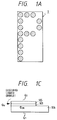
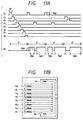
- Fig. 1A to 1C are typical views illustrating a character pattern and head driving pulses in a first example for the driving method for ink jet head according to the present invention.
- Fig. 2A is a circuit diagram exemplifying a driving circuit used in the first example
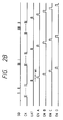
- Fig. 2B is a timing chart exemplifying actuating signals for the circuit of Fig. 2A.
- Fig. 3 is a graph illustrating the relation between the temperature of discharged ink and the residual energy of substrate.
- Fig. 4 is a typical perspective view illustrating an ink jet recording apparatus to which a head driving method according to the present invention is appropriately applied.
- Fig. 5 is a graph showing measurement results of the distribution of image OD value when the first example is applied.
- Fig. 6 is a timing chart exemplifying head driving pulses in a second example for the driving method of ink jet head according to the present invention.
- Fig. 7 is a circuit diagram exemplifying a driving circuit used in the second example.
- Fig. 8 is a flowchart illustrating an operation procedure in the second example.
- Fig. 9 is a timing chart exemplifying head driving pulses in a third example for the driving method of ink jet head according to the present invention.
- Fig. 10 is a circuit diagram exemplifying a driving circuit used in the third example.
- Fig. 11 is a flowchart illustrating an operation procedure in the third example.
- Fig. 12 is a timing chart exemplifying head driving pulses in a fourth example for the driving method of ink jet head according to the present invention.
- Fig. 13 is a typical view illustrating an head generating element of head used in the fourth example, and some states of producing a bubble.
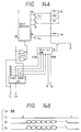
- Fig. 14A is a circuit diagram exemplifying a driving circuit used in the fourth example
- Fig. 14B is a timing chart illustrating actuating signals for the circuit of Fig. 14A.
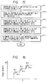
- Fig. 15 is a flowchart illustrating an operation procedure in the fourth example.
- Fig. 16 is a graph illustrating the distribution of image density when the fourth example is applied.
- Fig. 17A is a timing chart exemplifying head driving pulses in a fifth example for the driving method of ink jet head according to the present invention
- Fig. 17B is a typical view illustrating the arrangement of heat generating elements on the substrate of head used in the fifth example.
- Fig. 18A is a circuit diagram exemplifying a driving circuit used in the fifth example
- Fig. 18B is a timing chart illustrating actuating signals for the circuit of Fig. 18A.
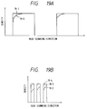
- Fig. 19A is a graph illustrating the distribution of image density when the fifth example is applied
- Fig. 19B is a graph illustrating the distribution of image density when the driving condition in the fifth example is changed.
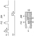
- Fig. 20A is a timing chart exemplifying head driving pulses in a sixth example for the driving method of ink jet head according to the present invention
- Fig. 20B is a partial longitudinal cross-sectional view illustrating the arrangement of heat generating elements of head used in the sixth example.
- Fig. 21 is a circuit diagram exemplifying a driving circuit used in the sixth example.
- Fig. 22 is a typical exploded perspective view illustrating a constitution of an ink jet head appropriate for use when the present invention is carried out.
- Fig. 23 is a graph illustrating the relation between the temperatures of substrate and support plate for head and the ink discharge volume.
- Fig. 24 is a timing chart illustrating the temperature variations of substrate and support plate after the driving of head has been started.
- Figs. 1A, 1B and 1C are views illustrating the driving pattern for heat generating element in the first example of the driving method for ink jet head according to the present invention.
- Fig. 2A is a driving circuit diagram used in the first example as shown in Fig. 1, and
- Fig. 2B is a timing chart for driving the circuit of Fig. 2A.
- Fig. 1A 1 shows an example of a character pattern, and in the same pattern, dots in each column are discharged at the same time.
- 11 is an electrical pulse wave shape to be given to each heat generating element in recording the first column of pattern.
- 12, 13 and 14 are electrical pulse wave shapes to each heat generating element in recording the second, third and fourth columns of pattern, respectively.
- the time interval ⁇ between electrical pulses is constant.
- a latch is contained in a shift register to transmit image data to be recorded, in synchronism with the clock, followed by a latch pulse.
- heat generating elements H 1 to H n corresponding to a plurality of discharge ports are undesirable to drive concurrently for a well known reason, they are divided into and driven in four blocks.
- a one-shot multivibrator is set at high level for a period of w 2 .
- heat generating elements are driven for the period of w 2 , regardless of image data.
- an ink jet head in the form as shown in Fig. 22 is used.
- This ink jet head is one in which image is recorded by discharging the ink through discharge ports by growth of bubbles owing to film boiling caused with the heat energy applied by the electro-thermal converters.
- the ink jet head has eight discharge ports 103 to each of which is connected one liquid channel 104 in which one heat generating element 102 for discharge is provided.
- the heat energy residual on the substrate 101 mainly propagates the support plate, where it is accumulated and radiated to the outside.
- w 1 is a pulse width for stable discharge of ink at the voltage V op suitable for a driving circuit.
- the ink is discharged by driving all heat generating elements 102 for discharge at each fixed interval ⁇ , with the pulse width w 1 . During this time, the temperature may gradually rise.
- the temperature of support plate 106 for the same head is detected using a thermistor, for example. If the temperature reaches a constant value, that temperature is set as T ⁇ .
- the temperature is also measured by applying electrical pulses having an appropriate pulse width w' shorter than W 1 and not large enough to discharge the ink to the heat generating elements at the same voltage as before, and if reaching a constant value, that temperature is set as T' ⁇ .
- T' ⁇ becomes substantially equal to T ⁇ . If T' ⁇ becomes substantially equal to T ⁇ , then w is set as w 2 .
- the permissible error between T' ⁇ and T ⁇ is 1 to 2 °C, depending the thermal resistance between the substrate 101 and the support plate 106, and the radiation resistance of the support plate 106.
- T env is the environmental temperature.
- the fact that the temperature on the substrate when electrical pulses are supplied to the heat generating elements at the pulse width w 1 is equal to the temperature when electrical pulses are supplied to the same heat generating elements at the pulse width w 2 means that both heat fluxes passing through the support plate are equal.
- the value of energy taken out is V op 2 /R n (w 1 - w 2 ) per discharge, where R n is the electrical resistance value of heat generating resistor.
- the energy ⁇ taken out to the external by the liquid droplets (ink) is CV d (T h - T env ).
- ⁇ , C are the density and specific heat of ink, respectively
- T h is the temperature in the vicinity of heat generating element when driven at the pulse width W 1 , which is approximately equal to the temperature of ink droplets for discharge.
- V x and T x are an increasing function of V x and T x , and so E rcs is regarded as the function of T x .
- T x (T h - T env )E res /(Nw 2 V op 2 /R h ) + T env is obtained.
- the temperature T x as indicated in the above expression is not necessarily reached, but is a converged value of temperature.
- Fig. 3 is a graph showing the relation between E rcs in the expression (5) and T x in the expression (6).
- 1 shows the line as indicated by the expression (6)
- Fig. 4 is a typical perspective view illustrating an ink jet recording apparatus appropriate for carrying out the driving method for ink jet head according to the present invention.
- the ink jet head 1 used in this example was mounted on a carriage 41 of the ink jet recording apparatus as shown in Fig. 4, and the discharge of black ink through each discharge port at intervals of 1 mm seconds, was repeated at a rate of 500 discharges per minute and 500 pauses, while the carriage was being moved at 0.16 m/s. Note that the carriage 41 on which the ink jet head 43 was mounted could reciprocate along guide rails 44.
- Fig. 5 is a graph showing the results.
- 50A, 50B, 50C and 50D are results from the above cases (A), (B), (C) and (D), respectively.
- the value of OD is constant from the beginning of recording, while in the case of (B), the value of OD is low at the beginning of recording.
- the driving method for ink jet head in this example is in principle effective to keep the image density constant if the variation of the room temperature is small within a recording time.
- control means is provided to reduce the variation of temperature on the support plate, and to cause a control circuit to control so that the temperature of the support plate may be kept at the same temperature as that when w 1 , w 2 are determined as previously described.
- the ceiling plate 1-5 is made of glass which has a low thermal conductivity, and covered with a resin, and further, in the vicinity of discharge ports 3, the substrate 101 may be covered with a casing having good thermal conductivity to which the temperature sensor and auxiliary heating means are attached.
- auxiliary heating means must not be directly provided on the substrate. The reason is that error may occur by the amount of thermal resistance between the substrate and the support plate, and is not negligible.
- w 2 as previously described can be determined with the following method.
- w 2 can be determined in such a method that in the state where temperature control means is operated under a constant environmental temperature in an environmental test room, the powers for making above control are made substantially equal, when the heat energy in accordance with image signal ON is continuously supplied to all the heat generating elements 102 on the substrate 101 and when the heat energy in accordance with image signal OFF is continuously supplied to all the heat generating elements 102.
- w 2 can be determined so that the difference between both powers lies within 5 %.
- the heat flux passing from the substrate 101 to the support plate 106 can be maintained constant, so that the substrate temperature can be kept constant.
- the driving method for ink jet head according to the present invention is also effective when the wiring resistance on the substrate for supplying the power to the heat generating elements is not negligible as compared with the electrical resistance of heat generating elements. Moreover, when a heat generative device such as a driver IC is mounted on the substrate, it is also applicable if the amount of heat generated by the device is substantially proportional to the length of enable signal.
- the objects of the present invention can be accomplished by temporarily dispersing the heat energy when image signal is OFF, as will be described later.
- Fig. 6 is a graph illustrating head driving pulses in the second example of the present invention.
- An ink jet head used in this example is the same as that in the first example.
- the use of the driving method in this example is effective.
- Fig. 7 shows an example of a circuit for carrying out the driving method of this example (example 2).
- resistors R 1 to R n are provided in parallel to the array of transistors at the output stage.
- the current will flow through the heat generating elements H 1 to H n , even when transistors in the transistor array are OFF.
- R 1 to R n are normally provided within the driving circuit of head, but can be provided within the head, particularly in the vicinities of heat generating elements H 1 to H n . In that case, the heat generated by the driving circuit can be made less than when provided within the driving circuit, so that the total consumption power can be reduced.
- Fig. 8 is a flowchart showing an example of a procedure for determining the driving voltage V op and the pulse width w 1 when image signal is ON, and the previously-mentioned steady minute voltage V DC .
- the first step S8-1 is a step of determining appropriately the steady minute voltage V DC in Fig. 21. This value is set at about one-several-th of presumed V op .
- the next step S8-2 is a step of determining experimentally V op and w 1 for stable discharge from all discharge ports by applying V DC .
- V op and w 1 are preferably set at their lower limits in a range of stable discharge.
- V op and w 1 is to be determined preferentially depends on the conditions of the circuit such as the type of driving transistor.
- the step S8-4 is a step where the V DC is only applied to the head
- the next step S8-5 is a step where if the temperature of support plate reaches a constant value, that constant temperature is set as T 2 .
- the step S8-6 is a step where T 1 and T 2 are compared. If both temperatures are substantially equal, V DC , V op and w 1 until this time are determined, and the procedure of this example is terminated.
- step S8-7 If T 2 > T 1 (step S8-7), the V DC is down (step S8-8), and the procedure returns to the step S8-2.
- step S8-9 If T 1 > T 2 , the V DC is up (step S8-9), and the procedure returns to the step S8-2.
- ⁇ T max is a tolerance for the difference between T 1 and T 2 , which is 1 to 2 °C, like in the example 1.
- V DC (NEW) V DC (OLD) (T 1 - T env )/(T 2 - T env )
- T env is the environmental temperature
- V DC (OLD) and V DC (NEW) are V DC before and after change in the steps S8-8 or S8-9, respectively.
- the procedure as shown in Fig. 8 can be performed manually like in the example 1, or automatically under the control of CPU.
- control means is provided to reduce the temperature variation of the support plate 105, like in the previous example, and by controlling the temperature of the support plate to be kept at the temperature when w 1 , V op and V DC are determined, the invariability of image density can be maintained at different room temperatures.
- the V DC can be selected so that the temporal average value of power for making the control as above described when image signal ON is continuously applied to all the heat generating elements is substantially equal to the temporal average value of power when image signal OFF is continuously applied to all the heat generating elements, or more specifically the difference is within 5 %.
- the driving method for ink jet head in this example is also effective when the wiring resistance on the substrate for supplying the power to the heat generating elements is not negligible as compared with the electrical resistance of heat generating elements.
- the driving method in this example is superior to the example 1 in that there is no discharge of ink when image signal is OFF , but has a larger power applied to the ink jet head than in the example 1.
- Fig. 9 is a graph illustrating head driving pulses in the third example of the driving method for ink jet head according to the present invention.
- the ink jet head used in this example is also the same as that in the examples 1 and 2.
- the feature of this example is that the heat energy generated regardless of image signal is caused by plural electrical pulses having minute widths.
- V OP and w 1 are the voltage and the pulse width of electrical pulse (discharge pulse) issued to the heat generating elements when image signal is ON.
- t p is a time during which a plurality of minute pulses are applied, i.e., the time from the start of applying minute pulses to the start of applying the pulse having the width w 1 as above indicated.
- w p and w f are the width of minute pulse and the cycle period. Accordingly, the number of minute pulses is about t p /w f .
- Fig. 10 shows an example of a driving circuit in the example 3 of Fig. 9.
- an one-shot multivibrator generates pulses during the time t p for applying minute pulses as above indicated.
- oscillator can generate rectangular waves having the frequency w f and duty w p /w f .
- the oscillator is not synchronized with other parts of the circuit, but can be constituted such that the oscillation is started with the enable signal.
- the ink discharge power is considered to be slightly stabler than in the illustrated example, but there is not almost any influence.
- Fig. 11 is a flowchart showing a procedure for determining V OP , w 1 , t p , w p and w f in this example.
- the first step S11-1 is a step of determining appropriately w p , w f and t p .
- the criterion is such that w p ⁇ t p /w f becomes almost the same as an anticipated w 1 .
- the next step S11-2 is a step of determining experimentally V OP and w 1 for stable discharge from all discharge ports by applying minute pulses with parameters as defined in S11-1. These V OP and w 1 are preferably set at their lower limits in a range of stable discharge.
- V OP and w 1 is to be determined preferentially depends on the conditions of the circuit such as the type of driving transistor.
- the step S11-4 is a step of applying the minute pulse only to the ink jet head, in which if the ink is discharged through any of discharge ports, the procedure proceeds to step S11-5 where at least one operation of shortening t p , shortening w p and lengthening w f is performed.
- step S11-6 the procedure waits until the temperature of support plate reaches a fixed value, and that constant temperature is set as T 2 .
- ⁇ T max is a tolerance for the difference between T 1 and T 2 , and is set to be about 1 to 2°C, like in the example 1.
- step S11-5 the procedure proceeds to the above step S11-5, where at least one operation of shortening t p , shortening w p and lengthening w f is performed.
- step S11-8 at least one operation of lengthening t p , lengthening w p and shortening w f is performed.
- test recording was performed in which solid image and blank were repeatedly recorded at intervals of 80 mms, in the same way as the example 1, for the ink jet head.
- the uniform image density could be obtained like in the example 1.
- control means is provided to reduce the temperature variation of the support plate 106, like in the examples 1 and 2, and by controlling the temperature of the support plate to be kept at the temperature when w p , t p , w f , w 1 and V OP are determined, the reproducibility of image density can be assured at largely different room temperatures.
- the w p , t p and w f can be selected so that the temporal average value of power for making the control as above described when image signal ON is continuously applied to all the heat generating elements is substantially equal to the temporal average value of power when image signal OFF is continuously applied to all the heat generating elements, or more specifically the difference is within 5%.
- the advantage of the driving method in this example is that the ink is not likely to be discharged when image signal is OFF, and the total amount of power supplied to the head is less than in the example 2.
- the driving circuit tends to be complicated.
- Fig. 12 is a graph illustrating head driving pulses in the fourth example of the driving method for ink jet head according to the present invention.
- the feature of this example is to use an ink jet head capable of four value gradation by changing the width of driving pulse.
- OFF, ON 1 , ON 2 and ON 3 illustrate the shapes of driving pulses at no image signal, level 1, level 2 and level 3, respectively.
- P 1 , P 2 and P 3 are driving pulses for causing the heat energy in accordance with image signal to be generated
- S 0 , S 1 and S 2 are driving pulses for causing the heat energy in accordance with the inverse of image signal to be generated.
- the under subscript indicates the level of signal, which means that the pulse having a greater number causes ink droplets having a larger volume to be discharged.
- Fig. 13 is a typical view illustrating schematically the shape of a heat generating element used in this example, and the size of bubble produced when a driving pulse is issed to the heat generating element.
- Fig. 13, 4 h shows the shape of a heater (heat generating element), the heater is of trapezoid form, and arranged on the substrate so that the driving voltage is applied between upper and lower bases of the trapezoid.
- 41, 42 and 43 show the shapes of bubbles produced at the image level 1, 2 and 3, respectively, in which if image level is higher, or the width of driving pulse is greater, bubble will be gradually produced in wider portion, and produced bubble becomes larger. As a result, the ink discharge volume becomes larger, with a larger dot being produced on recording medium.
- the constitution of head except for the heater (heat generating element) is the same as in the example 1.
- the ink jet head capable of gradient recording can control the stability or reproducibility of image density in more precise way than the two-value ink jet head used in the examples 1 to 3.
- the driving method in this example is especially effective.
- Fig. 14 is a view illustrating an example of a circuit for driving in this example (example 4).
- the heat generating elements H 1 to H n are driven sequentially one by one.
- the heat generating elements H 1 and H n are driven in a considerable time difference, but the problem that driving timing is shifted can be resolved by arranging the array of discharge ports slightly obliquely relative to a direction orthogonal to that of the relative movement between recording medium and the head.
- Fig. 14B shows a timing chart for driving the circuit of Fig. 14A.
- the clock is given a frequency sixteen times the timing for switching the discharge ports for driving.
- 2-bit image data is sent to D 1 and D 2 .
- a 64 x 1 bit ROM is connected to the output of a 4-bit counter, to the address input of which the above D 1 and D 2 are connected.
- 16 pulses of ON and OFF are sent in accordance with D 1 and D 2 while one heat generating element is selected, and correspondingly, the heat generating element can be driven.
- Fig. 15 is a flowchart showing an example of a procedure for determining the types of S 0 , S 1 , S 2 , P 1 , P 2 and P 3 as above described in this example (example 4).
- V d1 , V d2 and V d3 of Fig. 15 indicate the ink discharge volumes from the head with which desired image densities can be obtained at the image levels 1, 2 and 3, respectively.
- S15-1 is a step of determining the driving condition at the image level 3. That is, the voltage V OP and the pulse width w 3 to be applied to all the heat generating elements are adjusted so that the discharge volume is V d3 .
- next step S15-2 the procedure waits until the support plate temperature is constant, and sets the value of that temperature as T 3 .
- S15-3 is a step of determining the driving condition at the image level 2.
- the width w 2 of P 2 and the type (width, number and frequency of each minute pulse) of S 2 are adjusted so that the discharge volume is V d2 and the converged value of the support plate temperature is substantially equal to the value T 3 .
- S15-4 is a step of determining the driving condition at the image level 1.
- the width w 1 of P 1 and the type (width, number and frequency of each minute pulse) of S 1 are adjusted so that the discharge voluem is V d1 and the converged value of the support plate temperature is substantially equal to the value T 3 .
- S15-5 is a step of determining the type of S 0 . That is, the width, number and frequency of each minute pulse are determined so that the converged value of the support plate temperature is substantially equal to the value T 3 .
- the ink discharge volume may rely on measuring the consumed amount of ink, or collecting discharged ink in a collector bottle and measuring its weight.
- a specific criterion that the support plate temperature is substantially equal to T 3 is that its difference from T 3 is in a range from 1 to 2°C, as the practical decision, although it may depend on the construction of head.
- issuing the pulse to heat generating element can be determined uniformly to all the heat generating elements, or separately corresponding to each discharge port with the above procedure while measuring the ink discharge volume through that discharge port. In the latter case, troubles may be taken for setting up, but the dispersion of densities between discharge ports can be reduced.
- (E max -E)/(V max -V) in claim 1 is not only constant except when E is substantially equal to E max , but also (E 3 - E 2 )/(v 3 - v 2 ) and (E 3 - E 1 )/(v 3 - v 1 ) and (E 3 - E 0 )v 3 are equal and always constant.
- the image level 0 represents the image signal OFF.
- Fig. 16 is a graph illustrating the distribution of density when the head is driven under the driving condition set with the driving method of the above example (example 4).
- discharges of each 80 mm are performed in order of the image levels 0, 1, 2, 3, with a carriage speed of 0.16 m/s, and a discharge interval of 1 millisecond.
- 16-1, 16-2 and 16-3 show the density distributions at the image levels, 1, 2 and 3, respectively.
- 16-4, 16-5 and 16-6 show the density distributions at the image levels 1, 2 and 3, respectively, when the driving is performed having no heat energy generated in accordance with the inverse of image signal (conventional example).
- the driving in this example can make the image density more uniform than that of conventional one.
- the temporal average value of power for making the control when the heat energy in accordance with arbitrary image signal level including the case of image signal OFF is continuously applied to all the heat generating elements on the substrate uniformly is made substantially equal to the temporal average value of power for making the control when the heat energy in accordance with image signal different from the image signal level as above indicated is continuously applied to all the heat generating elements uniformly.
- Fig. 17A is a timing chart illustrating head driving pulses in the fifth example of the driving method for ink jet head according to the present invention
- Fig. 17B is a typical view illustrating the arrangement of heat generating elements on a substrate of head to which driving pulses are appropriately applied.
- the feature of this example is that the heat energy is generated in accordance with the inverse of image signal by heat generating element on the substrate other than those for discharge.
- H 1 to H 8 are heat generating elements for discharge
- H S is an auxiliary heat generating element for generating the heat energy in accordance with the inverse of image signal.
- An ink jet head for use in this example is substantially the same as that in the example 1, except for the arrangement of heat generating elements on the substrate.
- d 1 to d 8 show driving pulses applied to the heat generating elements H 1 to H 8 , respectively, and V OP is the voltage of driving pulse, w 1 is the pulse width, and ⁇ is the frequency.
- d s shows electrical pulses applied to the auxiliary heat generating element H S in accordance with the inverse of image signal, the length of that electrical pulse being proportional to the pulse width w 1 .
- auxiliary heat generating element H S should be allocated at the almost same distance from all the heat generating elements for discharge H 1 to H 8 .
- the w 1 and V OP can be determined in a range for stable discharge from each discharge port.
- the voltage of electrical pulse is arbitrary, but in this example, it is made the same voltage as V OP in order to simplify the circuit.
- the pulse width of the electrical pulse d s is set to be nxw 1 when the number of image signal OFFs is n, based on the pulse width w 1 .
- the method of determining the resistance value for the auxiliary heat generating element H S is one in which based on the same concept as in the example 1, assuming that the converged value of the temperature of support plate 106 is T 1 when the ink is continuously discharged through all discharge ports for each period ⁇ , and the converged value of the temperature of support plate 106 is T 2 when electrical pulses at the same voltage as that for discharge are applied to H S for each period ⁇ , the resistance value of H S can be determined so that T 1 is substantially equal to T 2 .
- the tolerance between T 1 and T 2 is about 1 to 2°C, like in the previous example.
- Fig. 18A is a view illustrating a circuit configuration for making the driving of head in this example (example 5).
- a decoder containing counter is used, in which one of the heating quantities Q 1 to Q 8 for the heat generating elements H 1 to H 8 is made at high level sequentially, and image data is sent in synchronism with it.
- Fig. 18B is a timing chart illustrating the timing for driving for heat generating element.
- M74HC4017 Mitsubishi Electric Corporation
- the method of driving the head in this example has an advantage that the circuit configuration for driving is made simpler.
- the distance between the auxiliary heat generating element H S and the heat generating elements for discharge H 1 to H 8 is about 5 mm on a Si sbustrate, it takes about 0.2 seconds for the heat to transfer by a distance of 5 mm on the Si substrate, based on a theory of heat conduction.
- the head when the recording is made by moving the head at a speed of 0.16 m/s, the head is moved about 3 cm during this period, so that the above time of heat conduction is not negligible.
- the total value of heat energy residual on the substrate always becomes constant, but the uneven distribution of heat may arise depending on image pattern.
- Fig. 19A is a graph illustrating the distribution of density in this case.
- FIG. 19A illustrates the distribution of density when no power is supplied to the auxiliary heat generating element H S
- 19-1 illustrates the distribution of density when electrical pulses are supplied to the auxiliary heat generating element H S in this example.
- Fig. 19B is a graph illustrating the distribution of density in recording solid image and blank at repetitive intervals (ON-OFF interval of image) the length of which is changed to an interval of 10 mm in the test of Fig. 19A.
- FIG. 19B illustrates the distribution of density when no power is supplied to the auxiliary heat generating element H S
- 19-3 illustrates the distribution of density when electrical pulses are supplied to the auxiliary heat generating element H S in this example.
- FIG. 19B 19-4 is illustrated as a reference when image is recorded with the driving method of previous example 1 using the recording head used in the example 1.
- control means was provided to reduce the temperature variation of support plate, and using a control circut, keep the temperature of support plate at the temperature when the resistance value of the auxiliary heat generating element H S was determined, so that more excellent image could be obtained.
- a method can be adopted for determining the resistance value of the auxiliary heat generating element H S in such a manner that in the state where the above control circuit is operated under the condition of constant room temperature, the temporal average value of power for making the control when the image signal ON is continuously applied to all the heat generating elements H 1 to H 8 is made substantially equal to the temporal average value of power for making the control when the image signal OFF is continuously applied to all the heat generating elements H 1 to H 8 , or more specifically, the difference between them is within 5%.
- Fig. 20A is a timing chart showing driving pulses in the sixth example of the driving method for ink jet head according to the present invention
- Fig. 20B is a partial longitudinal cross-sectional view illustrating the arrangement of heat generating elements within a liquid channel of the ink jet head used in Fig. 20A.
- the feature of this example is to drive a recording head having one heat generating element for generating the heat energy in accordance with image signal and one heat generating element for generating in accordance with the inverse of image signal, both of which are arranged in each discharge port.
- 20-A shows driving pulses dependent upon image signal
- 20-B shows driving pulses dependent upon the inverse of image signal
- 20-1 is a wall of liquid channel
- 20-2 is a heat generating element for generating the heat energy in accordance with image signal
- 20-3 is a heat generating element for generating the heat energy in accordance with the inverse of image signal
- 20-4 is an electrode common to both heat generating elements
- 20-5 is an electrode for supplying the electric power to the heat generating element 20-3
- 20-6 is an electrode for supplying the electric power to the heat generating element 20-2
- 20-7 is a discharge port.
- Electrical pulses of 20-A are supplied to the heat generating element 20-2, and electrical pulses of 20-B are supplied to the heat generating element 20-3.
- the ink jet head used in this example has the same configuration as that used in the example 1, except for portions shown in Fig. 20B.
- Fig. 21 is a view illustrating an electrical circuit used in making the driving of head in this example (example 6).
- the circuit of Fig. 21 is different from the circuit of example 5 as shown in Fig. 18A in that the quantity of heat generated in the heat generating elements H 1 to H n for discharge is adjusted by the resistance values of the heat generating elements H 1 ' to H n ' for generating large energy in accordance with the inverse of image signal.
- the heat generating elements H 1 ' to H n ' for generating the heat energy in accordance with the inverse of image signal are located farther away from the discharge ports than the heat generating elements H 1 to H n for generating the heat energy in accordance with image signal, it is easy to make a constitution so that the ink is not discharged by driving the heat generating elements H 1 ' to H n ' for adjustment.
- the abrupt change of image pattern can be more sufficiently coped with, as compared with the example 5.
- this example can be achieved using an ink jet head permitting the gradient recording as described with reference to Fig. 13 in the example 4 and having the heat generating elements of trapezoidal shape.
- the heat generating elements H 1 ' to H n ' for generating the heat energy regardless of image signal may still take the rectangular shape sufficiently.
- the present invention was described as being applied to an ink jet recording apparatus of the serial-scan type in which the ink jet head is mounted on the carriage 41, it will be appreciated that the present invention is applicable to an ink jet head of other recording methods, as used for the ink jet recording apparatus of line type of using the ink jet head of line type covering recording area in a paper width direction of recording medium, so that the same effects can be obtained.
- the present invention is applicable without regard to the number of ink jet heads mounted on the recording apparatus, for example, when a plurality of ink jet heads are used for the color recording.
- the present invention brings about excellent effects particularly in a recording head or a recording device of the bubble jet system proposed by CANON INC. among the various ink jet recording systems.
- This system is applicable to either of the so-called on-demand type and the continuous type.
- the case of the on-demand type is effective because, by applying at least one driving signal which gives rapid temperature elevation exceeding nucleus boiling corresponding to the recording information on electro-thermal converters arranged corresponding to the sheets or liquid channels holding a liquid (ink), heat energy is generated at the electro-thermal converters to effect film boiling at the heat acting surface of the recording head, and consequently the bubbles within the liquid (ink) can be formed corresponding one by one to the driving signals.
- the driving signals By making the driving signals into pulse shapes, growth and shrinkage of the bubble can be effected instantly and adequately to accomplish more preferably discharging of the liquid (ink) particularly excellent in response characteristic.
- the driving signals of such pulse shape those as disclosed in U. S. Patents 4,463,359 and 4,345,262 are suitable.
- the constitution of the recording head in addition to the combination of the discharging orifice, liquid channel, and electro-thermal converter (linear liquid channel or right-angled liquid channel) as disclosed in the above-mentioned respective specifications, the constitution by use of U. S. Patent 4,558,333, or 4,459,600 disclosing the constitution having the heat acting portion arranged in the flexed region is also included in the present invention.
- the present invention can be also effectively made the constitution as disclosed in Japanese Laid-Open Patent Application No. 59-123670 which disclosed the constitution using a slit common to a plurality of electro-thermal converters as the discharging portion of the electro-thermal converter or Japanese Laid-Open Patent Application No. 59-138461 which discloses the constitution having the opening for absorbing pressure wave of heat energy correspondent to the discharging portion.
- the recording head of the full line type having a length corresponding to the maximum width of a recording medium which can be recorded by the recording device
- either the constitution which satisfies its length by a combination of a plurality of recording heads as disclosed in the above-mentioned specifications or the constitution as one recording head integrally formed may be used, and the present invention can exhibit the effects as described above further effectively.
- the present invention is effective for a recording head of the freely exchangeable chip type which enables electrical connection to the main device or supply of ink from the main device by being mounted on the main device, or a recording head of the cartridge type integrally provided on the recording head itself.
- a restoration means for the recording head, a preliminary auxiliary means, etc. provided as the constitution of the recording device of the present invention is preferable, because the effect of the present invention can be further stabilized.
- these may include, for the recording head, capping means, cleaning means, pressurization or suction means, electro-thermal converters or another type of heating elements, or preliminary heating means according to a combination of these, and it is also effective for performing stable recording to perform preliminary mode which performs discharging separate from recording.
- the present invention is extremely effective for not only the recording mode only of a primary color such as black etc., but also a device equipped with at least one of plural different colors or full color by color mixing, whether the recording head may be either integrally constituted or combined in plural number.
- the ink is considered as the liquid in the examples of the present invention as described above, the present invention is applicable to either of the ink solid or liquefying at room temperature.
- the ink jet device as it is common to control the viscosity of ink to be maintained within a certain range for stable discharge by adjusting the temperature of ink in a range from 30 °C to 70 °C, the ink as liquefying when a recording enable signal is issued can be used.
- the ink having a property of liquefying only with the application of heat energy to be discharged as liquid ink is also applicable to the present invention.
- the ink may be in the form of being held in recesses or through holes of porous sheet as liquid or solid matter, and opposed to electro-thermal converters, as described in Japanese Laid-Open Patent Application No. 54-56847 or Japanese Laid-Open Patent Application No. 60-71260.
- the most effective method for inks as above described in the present invention is one based on the film boiling as above indicated.
- a driving method for an ink jet head comprising one or more discharge ports for discharging the ink, a substrate incorporating one or more heat generating elements for generating the heat energy, each of which is provided correspondent to each discharge port, and a support plate or casing on which said substrate is mounted, the driving method being capable of making the high-quality, stable recording without irregularities on image by equalizing the temperature distribution while maintaining the substrate temperature constant, with a simple construction having no provision of temperature detecting means or complex control means within the substrate, by taking such a constitution that when recording an image with the ink jet head in which the heat energy for discharging the ink in accordance with an image signal is generated in the heat generating elements, and the thermal resistance value passing through the support plate or casing is lower than that not passing through the support plate or casing among the thermal resistance between the substrate and the external, (E max -E)/(V max -V) is controlled to be always substantially constant whenever E ⁇ E max , providing that
Landscapes
- Particle Formation And Scattering Control In Inkjet Printers (AREA)
- Ink Jet (AREA)
- Television Signal Processing For Recording (AREA)
- Optical Filters (AREA)
Applications Claiming Priority (3)
| Application Number | Priority Date | Filing Date | Title |
|---|---|---|---|
| JP157256/90 | 1990-06-15 | ||
| JP2157256A JP2891748B2 (ja) | 1990-06-15 | 1990-06-15 | インクジェットヘッドの駆動方法 |
| EP91305439A EP0461936B1 (de) | 1990-06-15 | 1991-06-14 | Betriebsart für Farbstrahlkopf |
Related Parent Applications (1)
| Application Number | Title | Priority Date | Filing Date |
|---|---|---|---|
| EP91305439A Division EP0461936B1 (de) | 1990-06-15 | 1991-06-14 | Betriebsart für Farbstrahlkopf |
Publications (3)
| Publication Number | Publication Date |
|---|---|
| EP0822071A2 true EP0822071A2 (de) | 1998-02-04 |
| EP0822071A3 EP0822071A3 (de) | 1998-12-09 |
| EP0822071B1 EP0822071B1 (de) | 2006-02-08 |
Family
ID=15645677
Family Applications (2)
| Application Number | Title | Priority Date | Filing Date |
|---|---|---|---|
| EP97203078A Expired - Lifetime EP0822071B1 (de) | 1990-06-15 | 1991-06-14 | Ansteuerungsverfahren und Ansteuerungsvorrichtung für einen Tintenstrahldruckkopf |
| EP91305439A Expired - Lifetime EP0461936B1 (de) | 1990-06-15 | 1991-06-14 | Betriebsart für Farbstrahlkopf |
Family Applications After (1)
| Application Number | Title | Priority Date | Filing Date |
|---|---|---|---|
| EP91305439A Expired - Lifetime EP0461936B1 (de) | 1990-06-15 | 1991-06-14 | Betriebsart für Farbstrahlkopf |
Country Status (6)
| Country | Link |
|---|---|
| US (1) | US5798772A (de) |
| EP (2) | EP0822071B1 (de) |
| JP (1) | JP2891748B2 (de) |
| AT (2) | ATE170131T1 (de) |
| DE (2) | DE69133507T2 (de) |
| ES (1) | ES2118741T3 (de) |
Cited By (1)
| Publication number | Priority date | Publication date | Assignee | Title |
|---|---|---|---|---|
| EP0873869A3 (de) * | 1997-03-27 | 1999-08-25 | Lexmark International, Inc. | Druckkopf, Antriebsvorrichtung für Heizelemente eines Tintenstrahldruckkopfes, Heizelement für ein Substrat in einem Tintenstrahldrucker und Verfahren zur Steuerung solcher Heizelemente |
Families Citing this family (23)
| Publication number | Priority date | Publication date | Assignee | Title |
|---|---|---|---|---|
| US5237338A (en) * | 1991-08-05 | 1993-08-17 | Eastman Kodak Company | Is-enthalpic control of a thermal printing head |
| JPH0631932A (ja) * | 1992-07-14 | 1994-02-08 | Fuji Xerox Co Ltd | インクジェット記録装置 |
| JP3323664B2 (ja) * | 1994-09-09 | 2002-09-09 | キヤノン株式会社 | プリント装置 |
| US5969730A (en) * | 1994-11-07 | 1999-10-19 | Canon Aptex Inc. | Printer |
| JP3258878B2 (ja) * | 1994-12-02 | 2002-02-18 | セイコーエプソン株式会社 | サーマルヘッドの駆動制御方法およびその装置 |
| DE69622617T2 (de) * | 1995-04-03 | 2003-04-03 | Canon K.K., Tokio/Tokyo | Temperatursteuerung für ein Druckgerät |
| US6020905A (en) * | 1997-01-24 | 2000-02-01 | Lexmark International, Inc. | Ink jet printhead for drop size modulation |
| JP3372821B2 (ja) * | 1997-04-15 | 2003-02-04 | キヤノン株式会社 | インクジェット装置、該装置用インクジェットヘッドの温度推定方法および制御方法 |
| EP0890439A3 (de) * | 1997-07-11 | 1999-08-25 | Lexmark International, Inc. | Tintenstrahldruckkopf mit einer integrierten Steuerschaltung des Substratheizelementes |
| US6276770B1 (en) | 1998-11-17 | 2001-08-21 | Pitney Bowes Inc. | Mailing machine including ink jet printing having print head malfunction detection |
| US6612676B1 (en) | 1998-11-17 | 2003-09-02 | Pitney Bowes Inc. | Apparatus and method for real-time measurement of digital print quality |
| US6435642B1 (en) | 1998-11-17 | 2002-08-20 | Pitney Bowes Inc. | Apparatus and method for real-time measurement of digital print quality |
| US6350006B1 (en) | 1998-11-17 | 2002-02-26 | Pitney Bowes Inc. | Optical ink drop detection apparatus and method for monitoring operation of an ink jet printhead |
| TW590896B (en) * | 2003-09-12 | 2004-06-11 | Ind Tech Res Inst | Inkjet control method of micro fluid |
| US20070297349A1 (en) * | 2003-11-28 | 2007-12-27 | Ofir Arkin | Method and System for Collecting Information Relating to a Communication Network |
| US8491076B2 (en) | 2004-03-15 | 2013-07-23 | Fujifilm Dimatix, Inc. | Fluid droplet ejection devices and methods |
| US7281778B2 (en) | 2004-03-15 | 2007-10-16 | Fujifilm Dimatix, Inc. | High frequency droplet ejection device and method |
| KR20070087223A (ko) | 2004-12-30 | 2007-08-27 | 후지필름 디마틱스, 인크. | 잉크 분사 프린팅 |
| JP4341582B2 (ja) * | 2005-05-31 | 2009-10-07 | セイコーエプソン株式会社 | 液滴吐出装置 |
| US7988247B2 (en) | 2007-01-11 | 2011-08-02 | Fujifilm Dimatix, Inc. | Ejection of drops having variable drop size from an ink jet printer |
| JP5268285B2 (ja) * | 2007-06-01 | 2013-08-21 | キヤノン株式会社 | 記録装置 |
| US8393702B2 (en) | 2009-12-10 | 2013-03-12 | Fujifilm Corporation | Separation of drive pulses for fluid ejector |
| JP6083589B2 (ja) * | 2012-02-13 | 2017-02-22 | パナソニックIpマネジメント株式会社 | インクジェット装置および有機el表示パネルの製造方法 |
Family Cites Families (35)
| Publication number | Priority date | Publication date | Assignee | Title |
|---|---|---|---|---|
| CA1127227A (en) * | 1977-10-03 | 1982-07-06 | Ichiro Endo | Liquid jet recording process and apparatus therefor |
| JPS5936879B2 (ja) * | 1977-10-14 | 1984-09-06 | キヤノン株式会社 | 熱転写記録用媒体 |
| US4330787A (en) * | 1978-10-31 | 1982-05-18 | Canon Kabushiki Kaisha | Liquid jet recording device |
| US4345262A (en) * | 1979-02-19 | 1982-08-17 | Canon Kabushiki Kaisha | Ink jet recording method |
| US4463359A (en) * | 1979-04-02 | 1984-07-31 | Canon Kabushiki Kaisha | Droplet generating method and apparatus thereof |
| US4313124A (en) * | 1979-05-18 | 1982-01-26 | Canon Kabushiki Kaisha | Liquid jet recording process and liquid jet recording head |
| US4558333A (en) * | 1981-07-09 | 1985-12-10 | Canon Kabushiki Kaisha | Liquid jet recording head |
| JPS58220757A (ja) * | 1982-06-18 | 1983-12-22 | Canon Inc | 液体噴射記録装置 |
| JPS59123670A (ja) * | 1982-12-28 | 1984-07-17 | Canon Inc | インクジエツトヘツド |
| JPS59138461A (ja) * | 1983-01-28 | 1984-08-08 | Canon Inc | 液体噴射記録装置 |
| US4566813A (en) * | 1983-09-27 | 1986-01-28 | Mitsubishi Denki Kabushiki Kaisha | Dot-matrix print controller |
| JPS6071260A (ja) * | 1983-09-28 | 1985-04-23 | Erumu:Kk | 記録装置 |
| JPS60139465A (ja) * | 1983-12-28 | 1985-07-24 | Fuji Xerox Co Ltd | サ−マルヘツド駆動装置 |
| JPS61146550A (ja) * | 1984-12-21 | 1986-07-04 | Canon Inc | 液体噴射記録装置 |
| US4660056A (en) * | 1984-03-23 | 1987-04-21 | Canon Kabushiki Kaisha | Liquid jet recording head |
| JPS60219060A (ja) * | 1984-04-17 | 1985-11-01 | Canon Inc | 液体噴射記録装置 |
| JPS60248357A (ja) * | 1984-05-25 | 1985-12-09 | Canon Inc | 液体噴射記録装置 |
| JPS61112664A (ja) * | 1984-11-06 | 1986-05-30 | Konishiroku Photo Ind Co Ltd | サ−マルプリンタ |
| JPS61189948A (ja) * | 1985-02-19 | 1986-08-23 | Alps Electric Co Ltd | インク・ジエツトのヘツド駆動制御方式 |
| DE3612469C2 (de) * | 1985-04-15 | 1999-02-18 | Canon Kk | Tintenstrahl-Aufzeichnungsgerät |
| JPS61249763A (ja) * | 1985-04-30 | 1986-11-06 | Canon Inc | 液体噴射記録装置 |
| US4791453A (en) * | 1986-03-14 | 1988-12-13 | Konishiroku Photo Industry Co., Ltd. | Recording apparatus |
| JPH0729436B2 (ja) * | 1986-03-24 | 1995-04-05 | キヤノン株式会社 | 液体噴射記録ヘツド |
| JPS63116857A (ja) * | 1986-11-06 | 1988-05-21 | Canon Inc | 液体噴射記録ヘツド |
| JPS63134249A (ja) * | 1986-11-26 | 1988-06-06 | Canon Inc | 液体噴射記録ヘツド |
| JP2904489B2 (ja) * | 1987-11-12 | 1999-06-14 | キヤノン株式会社 | 記録ヘッドの制御回路 |
| JP2801196B2 (ja) * | 1987-11-20 | 1998-09-21 | キヤノン株式会社 | 液体噴射装置 |
| JPH01184416A (ja) * | 1988-01-18 | 1989-07-24 | Chino Corp | 計器 |
| US4899180A (en) * | 1988-04-29 | 1990-02-06 | Xerox Corporation | On chip heater element and temperature sensor |
| JPH02231148A (ja) * | 1988-11-04 | 1990-09-13 | Canon Inc | 記録ヘッド駆動方法および前記ヘッド駆動方法を用いた記録装置 |
| US4910528A (en) * | 1989-01-10 | 1990-03-20 | Hewlett-Packard Company | Ink jet printer thermal control system |
| US5172134A (en) * | 1989-03-31 | 1992-12-15 | Canon Kabushiki Kaisha | Ink jet recording head, driving method for same and ink jet recording apparatus |
| JPH0343254A (ja) * | 1989-07-03 | 1991-02-25 | Xerox Corp | 熱インクジェットの印字ヘッド |
| US5107276A (en) * | 1989-07-03 | 1992-04-21 | Xerox Corporation | Thermal ink jet printhead with constant operating temperature |
| JP3043254U (ja) | 1996-12-20 | 1997-11-18 | 晴江 大島 | ショルダーアームウォーマー 肩腕就寝防寒具 |
-
1990
- 1990-06-15 JP JP2157256A patent/JP2891748B2/ja not_active Expired - Fee Related
-
1991
- 1991-06-14 AT AT91305439T patent/ATE170131T1/de not_active IP Right Cessation
- 1991-06-14 AT AT97203078T patent/ATE317330T1/de not_active IP Right Cessation
- 1991-06-14 DE DE69133507T patent/DE69133507T2/de not_active Expired - Lifetime
- 1991-06-14 EP EP97203078A patent/EP0822071B1/de not_active Expired - Lifetime
- 1991-06-14 ES ES91305439T patent/ES2118741T3/es not_active Expired - Lifetime
- 1991-06-14 EP EP91305439A patent/EP0461936B1/de not_active Expired - Lifetime
- 1991-06-14 DE DE69130037T patent/DE69130037T2/de not_active Expired - Lifetime
-
1997
- 1997-05-19 US US08/848,722 patent/US5798772A/en not_active Expired - Lifetime
Cited By (1)
| Publication number | Priority date | Publication date | Assignee | Title |
|---|---|---|---|---|
| EP0873869A3 (de) * | 1997-03-27 | 1999-08-25 | Lexmark International, Inc. | Druckkopf, Antriebsvorrichtung für Heizelemente eines Tintenstrahldruckkopfes, Heizelement für ein Substrat in einem Tintenstrahldrucker und Verfahren zur Steuerung solcher Heizelemente |
Also Published As
| Publication number | Publication date |
|---|---|
| ATE170131T1 (de) | 1998-09-15 |
| DE69133507T2 (de) | 2006-08-10 |
| EP0822071B1 (de) | 2006-02-08 |
| JPH0447948A (ja) | 1992-02-18 |
| EP0461936B1 (de) | 1998-08-26 |
| ATE317330T1 (de) | 2006-02-15 |
| EP0822071A3 (de) | 1998-12-09 |
| EP0461936A2 (de) | 1991-12-18 |
| ES2118741T3 (es) | 1998-10-01 |
| EP0461936A3 (en) | 1992-07-29 |
| DE69130037D1 (de) | 1998-10-01 |
| US5798772A (en) | 1998-08-25 |
| DE69130037T2 (de) | 1999-02-18 |
| DE69133507D1 (de) | 2006-04-20 |
| JP2891748B2 (ja) | 1999-05-17 |
Similar Documents
| Publication | Publication Date | Title |
|---|---|---|
| EP0461936B1 (de) | Betriebsart für Farbstrahlkopf | |
| US5559535A (en) | Temperature control of ink-jet recording head using heat energy | |
| US6193344B1 (en) | Ink jet recording apparatus having temperature control function | |
| EP1093918B1 (de) | System und Verfahren zur Regelung der Temperatur eines Tintenstrahldruckkopfes unter Verwendung einer dynamischen Pulsbreiteneinstellung | |
| JP3247412B2 (ja) | インクジェット記録方法、インクジェット記録装置、およびインクジェット記録ヘッド | |
| JP3337912B2 (ja) | インクジェットヘッドの駆動方法及びこれを実行するインクジェット装置 | |
| JP3083441B2 (ja) | プリントヘッド及びその製造装置及び製造方法及びプリント装置 | |
| EP0505154B1 (de) | Temperatursteuerung für thermischen Tintenstrahlaufzeichnungskopf | |
| JP3117854B2 (ja) | インクジェット装置および該装置用インクジェットヘッドの制御方法 | |
| JPH10286964A (ja) | インクジェット装置、該装置用インクジェットヘッドの温度推定方法および制御方法 | |
| JP2877971B2 (ja) | インクジェット記録装置 | |
| US6312078B1 (en) | Imaging apparatus and method of providing images of uniform print density | |
| EP0750988A2 (de) | Tintenstrahldruckvorrichtung, Vorrichtung zum Treiben einer Tintenstrahldruckvorrichtung und Tintenstrahldruckverfahren | |
| EP0816084A2 (de) | Verfahren zum zeitversetzten Steuern von mehreren Heizelementen | |
| EP0416557B1 (de) | Verfahren zum Bedrucken unterschiedlicher Druckmedien | |
| JP3247404B2 (ja) | インクジェット記録ヘッドの吐出制御方法およびインクジェット記録装置 | |
| JP2731012B2 (ja) | インクジェット記録装置 | |
| US5452095A (en) | Recording apparatus and method having a recording mode which repeatedly records recording data for one line a plurality of times | |
| JPH09104111A (ja) | インクジェット記録装置 | |
| JP3207652B2 (ja) | プリント素子情報検出装置、プリントヘッド駆動装置および前記装置を具えた印刷装置 | |
| JP2004195760A (ja) | 記録装置 | |
| JP2986883B2 (ja) | インクジェット記録装置 | |
| JP2003320678A (ja) | ヘッドユニット及びインクジェット式記録装置並びにインクジェット式記録方法 | |
| JP2000085117A (ja) | 記録ヘッド補正方法及びその装置及びその装置によって補正された記録ヘッド及びその記録ヘッドを用いた記録装置 | |
| US5808632A (en) | Recording apparatus and method using ink jet recording head |
Legal Events
| Date | Code | Title | Description |
|---|---|---|---|
| PUAI | Public reference made under article 153(3) epc to a published international application that has entered the european phase |
Free format text: ORIGINAL CODE: 0009012 |
|
| AC | Divisional application: reference to earlier application |
Ref document number: 461936 Country of ref document: EP |
|
| AK | Designated contracting states |
Kind code of ref document: A2 Designated state(s): AT BE CH DE DK ES FR GB GR IT LI LU NL SE |
|
| PUAL | Search report despatched |
Free format text: ORIGINAL CODE: 0009013 |
|
| AK | Designated contracting states |
Kind code of ref document: A3 Designated state(s): AT BE CH DE DK ES FR GB GR IT LI LU NL SE |
|
| 17P | Request for examination filed |
Effective date: 19990421 |
|
| 17Q | First examination report despatched |
Effective date: 20010619 |
|
| GRAP | Despatch of communication of intention to grant a patent |
Free format text: ORIGINAL CODE: EPIDOSNIGR1 |
|
| RTI1 | Title (correction) |
Free format text: METHOD AND APPARATUS FOR DRIVING AN INK JET HEAD |
|
| GRAS | Grant fee paid |
Free format text: ORIGINAL CODE: EPIDOSNIGR3 |
|
| GRAA | (expected) grant |
Free format text: ORIGINAL CODE: 0009210 |
|
| AC | Divisional application: reference to earlier application |
Ref document number: 0461936 Country of ref document: EP Kind code of ref document: P |
|
| AK | Designated contracting states |
Kind code of ref document: B1 Designated state(s): AT BE CH DE DK ES FR GB GR IT LI LU NL SE |
|
| PG25 | Lapsed in a contracting state [announced via postgrant information from national office to epo] |
Ref country code: NL Free format text: LAPSE BECAUSE OF FAILURE TO SUBMIT A TRANSLATION OF THE DESCRIPTION OR TO PAY THE FEE WITHIN THE PRESCRIBED TIME-LIMIT Effective date: 20060208 Ref country code: LI Free format text: LAPSE BECAUSE OF FAILURE TO SUBMIT A TRANSLATION OF THE DESCRIPTION OR TO PAY THE FEE WITHIN THE PRESCRIBED TIME-LIMIT Effective date: 20060208 Ref country code: IT Free format text: LAPSE BECAUSE OF FAILURE TO SUBMIT A TRANSLATION OF THE DESCRIPTION OR TO PAY THE FEE WITHIN THE PRESCRIBED TIME-LIMIT;WARNING: LAPSES OF ITALIAN PATENTS WITH EFFECTIVE DATE BEFORE 2007 MAY HAVE OCCURRED AT ANY TIME BEFORE 2007. THE CORRECT EFFECTIVE DATE MAY BE DIFFERENT FROM THE ONE RECORDED. Effective date: 20060208 Ref country code: CH Free format text: LAPSE BECAUSE OF FAILURE TO SUBMIT A TRANSLATION OF THE DESCRIPTION OR TO PAY THE FEE WITHIN THE PRESCRIBED TIME-LIMIT Effective date: 20060208 Ref country code: BE Free format text: LAPSE BECAUSE OF FAILURE TO SUBMIT A TRANSLATION OF THE DESCRIPTION OR TO PAY THE FEE WITHIN THE PRESCRIBED TIME-LIMIT Effective date: 20060208 Ref country code: AT Free format text: LAPSE BECAUSE OF FAILURE TO SUBMIT A TRANSLATION OF THE DESCRIPTION OR TO PAY THE FEE WITHIN THE PRESCRIBED TIME-LIMIT Effective date: 20060208 |
|
| REG | Reference to a national code |
Ref country code: GB Ref legal event code: FG4D |
|
| REG | Reference to a national code |
Ref country code: CH Ref legal event code: EP |
|
| REF | Corresponds to: |
Ref document number: 69133507 Country of ref document: DE Date of ref document: 20060420 Kind code of ref document: P |
|
| PG25 | Lapsed in a contracting state [announced via postgrant information from national office to epo] |
Ref country code: SE Free format text: LAPSE BECAUSE OF FAILURE TO SUBMIT A TRANSLATION OF THE DESCRIPTION OR TO PAY THE FEE WITHIN THE PRESCRIBED TIME-LIMIT Effective date: 20060508 Ref country code: DK Free format text: LAPSE BECAUSE OF FAILURE TO SUBMIT A TRANSLATION OF THE DESCRIPTION OR TO PAY THE FEE WITHIN THE PRESCRIBED TIME-LIMIT Effective date: 20060508 |
|
| PG25 | Lapsed in a contracting state [announced via postgrant information from national office to epo] |
Ref country code: ES Free format text: LAPSE BECAUSE OF FAILURE TO SUBMIT A TRANSLATION OF THE DESCRIPTION OR TO PAY THE FEE WITHIN THE PRESCRIBED TIME-LIMIT Effective date: 20060519 |
|
| NLV1 | Nl: lapsed or annulled due to failure to fulfill the requirements of art. 29p and 29m of the patents act | ||
| REG | Reference to a national code |
Ref country code: CH Ref legal event code: PL |
|
| PLBE | No opposition filed within time limit |
Free format text: ORIGINAL CODE: 0009261 |
|
| STAA | Information on the status of an ep patent application or granted ep patent |
Free format text: STATUS: NO OPPOSITION FILED WITHIN TIME LIMIT |
|
| 26N | No opposition filed |
Effective date: 20061109 |
|
| EN | Fr: translation not filed | ||
| PG25 | Lapsed in a contracting state [announced via postgrant information from national office to epo] |
Ref country code: GR Free format text: LAPSE BECAUSE OF FAILURE TO SUBMIT A TRANSLATION OF THE DESCRIPTION OR TO PAY THE FEE WITHIN THE PRESCRIBED TIME-LIMIT Effective date: 20060509 Ref country code: FR Free format text: LAPSE BECAUSE OF FAILURE TO SUBMIT A TRANSLATION OF THE DESCRIPTION OR TO PAY THE FEE WITHIN THE PRESCRIBED TIME-LIMIT Effective date: 20070330 |
|
| PG25 | Lapsed in a contracting state [announced via postgrant information from national office to epo] |
Ref country code: LU Free format text: LAPSE BECAUSE OF NON-PAYMENT OF DUE FEES Effective date: 20060614 |
|
| PG25 | Lapsed in a contracting state [announced via postgrant information from national office to epo] |
Ref country code: FR Free format text: LAPSE BECAUSE OF FAILURE TO SUBMIT A TRANSLATION OF THE DESCRIPTION OR TO PAY THE FEE WITHIN THE PRESCRIBED TIME-LIMIT Effective date: 20060208 |
|
| PGFP | Annual fee paid to national office [announced via postgrant information from national office to epo] |
Ref country code: GB Payment date: 20100401 Year of fee payment: 20 Ref country code: DE Payment date: 20100630 Year of fee payment: 20 |
|
| REG | Reference to a national code |
Ref country code: DE Ref legal event code: R071 Ref document number: 69133507 Country of ref document: DE |
|
| REG | Reference to a national code |
Ref country code: DE Ref legal event code: R071 Ref document number: 69133507 Country of ref document: DE |
|
| REG | Reference to a national code |
Ref country code: GB Ref legal event code: PE20 Expiry date: 20110613 |
|
| PG25 | Lapsed in a contracting state [announced via postgrant information from national office to epo] |
Ref country code: GB Free format text: LAPSE BECAUSE OF EXPIRATION OF PROTECTION Effective date: 20110613 |
|
| PG25 | Lapsed in a contracting state [announced via postgrant information from national office to epo] |
Ref country code: DE Free format text: LAPSE BECAUSE OF EXPIRATION OF PROTECTION Effective date: 20110615 |