EP0822176A2 - Verfahren zur Herstellung hochreiner Terephthalsäure unter Verwendung der Dispersionsmedium-Versetzungsvorrichtung - Google Patents
Verfahren zur Herstellung hochreiner Terephthalsäure unter Verwendung der Dispersionsmedium-Versetzungsvorrichtung Download PDFInfo
- Publication number
- EP0822176A2 EP0822176A2 EP97112164A EP97112164A EP0822176A2 EP 0822176 A2 EP0822176 A2 EP 0822176A2 EP 97112164 A EP97112164 A EP 97112164A EP 97112164 A EP97112164 A EP 97112164A EP 0822176 A2 EP0822176 A2 EP 0822176A2
- Authority
- EP
- European Patent Office
- Prior art keywords
- dispersion medium
- slurry
- terephthalic acid
- bottom portion
- replacement
- Prior art date
- Legal status (The legal status is an assumption and is not a legal conclusion. Google has not performed a legal analysis and makes no representation as to the accuracy of the status listed.)
- Granted
Links
Images

Classifications
-
- C—CHEMISTRY; METALLURGY
- C07—ORGANIC CHEMISTRY
- C07C—ACYCLIC OR CARBOCYCLIC COMPOUNDS
- C07C63/00—Compounds having carboxyl groups bound to a carbon atoms of six-membered aromatic rings
- C07C63/14—Monocyclic dicarboxylic acids
- C07C63/15—Monocyclic dicarboxylic acids all carboxyl groups bound to carbon atoms of the six-membered aromatic ring
- C07C63/26—1,4 - Benzenedicarboxylic acid
-
- C—CHEMISTRY; METALLURGY
- C07—ORGANIC CHEMISTRY
- C07C—ACYCLIC OR CARBOCYCLIC COMPOUNDS
- C07C51/00—Preparation of carboxylic acids or their salts, halides or anhydrides
- C07C51/42—Separation; Purification; Stabilisation; Use of additives
-
- C—CHEMISTRY; METALLURGY
- C07—ORGANIC CHEMISTRY
- C07C—ACYCLIC OR CARBOCYCLIC COMPOUNDS
- C07C51/00—Preparation of carboxylic acids or their salts, halides or anhydrides
- C07C51/42—Separation; Purification; Stabilisation; Use of additives
- C07C51/43—Separation; Purification; Stabilisation; Use of additives by change of the physical state, e.g. crystallisation
Definitions
- the present invention relates to a process for producing highly pure terephthalic acid by the use of a dispersion medium replacement apparatus. More particularly, it pertains to a process for producing highly pure terephthalic acid which comprises replacing, with another solvent for the purpose of purifying terephthalic acid, a dispersion medium in a slurry of crude terephthalic acid crystals which has been obtained by a liquid-phase oxidation reaction, or a dispersion medium in a slurry of terephthalic acid crystals which contains a considerable amount of impurities and which has been obtained by subjecting crude terephthalic acid to a catalytic hydrogenation treatment or a recrystallization treatment.
- Terephthalic acid is produced by liquid-phase oxidation of a p-phenylene compound such as p-alkylbenzene typified by p-xylene.
- a p-phenylene compound such as p-alkylbenzene typified by p-xylene.
- acetic acid as a solvent
- a catalyst such as cobalt and manganese incorporated as necessary, with a promotor exemplified by a bromine compound and acetaldehyde.
- a method for purifying the crude terephthalic acid obtained by the liquid-phase oxidation reaction mention is made of various known methods such as a method in which the crude terephthalic acid is dissolved in a solvent such as acetic acid, water or a mixed solvent thereof at a high temperature and high puresure and the resultant solution is subjected to a treatment by hydrogenation, decarbonization, oxidation or recrystallization and a method in which the crude terephthalic acid is subjected to an immersion treatment at a high temperature under a slurry condition in which terephthalic acid crystals are partially dissolved.
- a solvent such as acetic acid, water or a mixed solvent thereof
- the oxidation intermediate such as 4 CBA and p-TOL, and color causative substances that are present as impurities, in the oxidation reaction product or in the slurry formed by purification treatment of the crude terephthalic acid are almost dissolved in the dispersion medium at a high temperature, but when any of the slurries is cooled to about 100°C to form a slurry containing terephthalic acid crystal, these impuriteis are incorporated into the terephthalic acid crystal, thereby making it difficult to produce highly pure terephthalic acid.
- the most prevailing method for separating a dispersion medium from a slurry containing a crystal is centrifugal separation method, which is widely used also in the case of separating terephthalic acid crystals.
- the centrifugal separation method is a method in which a slurry is introduced into a basket rotating at high speed to allow separated dispersion medium to overflow at the upside, and to direct separated crystals towards the underside. It is known, however, that a continuous operation of a centrifugal separator at a high temperature and pressure is accompanied by several difficulties arising from the restriction on the constitution and function of the centrifugal separator.
- the above-mentioned apparatus has four outlet/inlet ports including (1) a feed port for feeding an original slurry composed of a first dispersion medium and terephthalic acid crystals; (2) a feed port for introducing a second dispersion medium; (3) a discharge port for taking out a replaced slurry composed mainly of the terephthalic acid crystals and the second dispersion medium; and (4) a discharge port mainly for discharging the first dispersion medium.
- the feed rate or discharge rate other than the feed rate through the port (1) can optionally be varied, and such variation gives rise to operational flexibility and at the same time, exerts significant influence on the performance such as the replacement efficiency for the dispersion medium.
- the flow rate management in the aforesaid system is considerably complicated, thereby making it difficult to stably and steadily operate the dispersion medium replacement apparatus.
- the dispersion medium replacement appparatus can be easily administrated by controlling the feed rate of the second dispersion medium and/or the takeout rate of the replaced slurry so as to maintain a temperature zone showing sharp change in temperature which can exist when the temperature distribution inside said apparatus is regulated so that the upper portion thereof is set to a higher temperature.
- the present invention has been accomplished by the aforestated finding.
- the present invention provides a process for producing highly pure terephthalic acid by the use of a dispersion medium replacement apparatus equipped with a stirring unit at the bottom portion thereof for uniform dispersion therein, wherein an original slurry comprising a first dispersion medium and terephthalic acid crystals is introduced into a dispersion medium replacement apparatus at the top portion thereof, a second dispersion medium is introduced into said apparatus at the bottom portion thereof, a replaced slurry comprising principally the second dispersion medium and the terephthalic acid crystals is taken out from said apparatus at the bottom portion thereof, and the first dispersion medium as a major component is taken out from said apparatus at the top portion thereof, which process comprises maintaining a uniformly dispersed slurry at the bottom portion of the apparatus at a concentration higher than that of a slurry at the intermediate portion thereof; maintaining the upper portion thereof at a higher temperature in a vertical temperature distribution therein to form a temperature change zone; and controlling at least one of the feed rate of the second dispersion medium and
- FIG.1 is a drawing showing an example of a block flow diagram of a process for producing highly pure terephthalic acid and a flow diagram of a dispersion medium replacement apparatus in the present invention
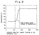
- FIG.2 is a drawing showing a result of a measurement of a temperature distribution inside a dispersion medium replacement apparatus in Example 1.
- the dispersion medium replacement apparatus is employed for the treatment of a slurry of crude terephthalic acid crystals which has been obtained by a liquid-phase oxidation reaction, or a slurry of terephthalic acid crystals which contains a considerable amount of impurities and which has been obtained by subjecting crude terephalic acid to a catalytic hydrogenation treatment or a recrystallication treatment.
- acetic acid as a solvent is frequently used in a liquid-phase reaction, while water as a solvent is frequently used in a catalytic hydrogenation treatment.
- a first and a second dispersion media are acetic acid and water, respectively.
- the above-mentioned apparatus according to the present invention is usable also for purifying a slurry of terephthalic acid crystals, and in the case, for example, of purifying treating a slurry of terephthalic acid crystals obtained by the above-mentioned catalytic hydrogenation treatment, the first and second dispersion media are each water.
- the first dispersion medium that is, the dispersion medium to be replaced may be the same as or different from the second dispersion medium, that is, the replacing medium.
- the dispersion medium replacement apparatus need not internal trays in particular, and is usually in the form of empty tower.
- the stirring unit to be placed at the bottom portion of the apparatus needs only to be capable of substantially uniformly dispersing the slurry at the bottom portion thereof.
- Examples of the usable stirring unit include so called a stirrer equipped with various agitation impellers and a circulation pump which causes mixed flow at the bottom portion thereof.
- it is preferably carried out to install baffle plates to promote stirring.
- the concentration of the slurry at the bottom portion thereof can be kept at a high level by controlling the feed rate of the dispersion medium to be fed at the bottom portion as well as the takeout rate of the replaced slurry.
- a slight upward stream be generated in the apparatus in order to maintain a high replacement efficiency in the apparatus.
- a part of the first dispersion medium to be discharged at the port (4) is sometimes mixed in the stream towards the discharge port (3) of the replaced slurry, which is an unfavorable factor of impairing the object of replacing the first dispersion medium with the second dispersion medium. Accordingly, such a downward stream should be prevented by al means. It is also known that the performance of the apparatus greatly depends upon the intensity of the upward stream.
- the stream in the dispersion medium replacement apparatus is the difference between the feed rate of the second dispersion medium (2) and the takeout rate of the liquid components in the replaced slurry (3), and thus the stream can not be regulated as an independent flow rate.
- the solid concentration in the replaced slurry in order to recognize the flow rate of the liquid components in the replaced slurry.
- the solid concentration is a physical quantity involving much errors among all physical quantities to be detected, whereby it is extremely difficult to detect the same on time.
- the upward flow rate to be administrated in the apparatus is a slight flow rate about one tenth the main flow rate which is the basis of the difference, and therefore some accuracy of the detected solid concentration is required in response to the aforesaid slight flow rate.
- the administration of the flow rate is, of course, made easy by increasing the upward flow rate.
- the upward flow rate is increased, it consequently follows that the amount of the first dispersion medium discharged at (4) is increased.
- the first dispersion medium is finally discharged outside the system as an effluent. Accordingly, from the aspect of minimizing the amount of the effluent, the upward flow rate must be restricted without any choice.
- the position of the zone is elevated with increase in the upward stream, and is lowered with decrease in the upward stream. Accordingly, the detection of the lowered zone means a decrease in the upward stream.
- the upward stream is intensified to maintain high replacement efficiency in the dispersion medium replacement apparatus by carrying out a procedure of intensifying the upward stream, for example, a procedure of increasing the feed rate of the second dispersion medium, or decreasing the takeout rate of the replaced slurry.
- the procedure of causing tremperature difference between the upper portion and the lower portion, that is, operating the vertical temperature distribution so as to maintain the upper portion at a higher temperature can be put into practice, for example, by setting the temperature of the second dispersion medium to a temperature lower than that of the feed slurry.
- the adoption of the aforesaid operational method enables not only the replacement efficiency in the apparatus to be maintained at a high level, but also the operational system to be more steadily constituted by the specific gravity of the dispersion medium in the slurry at the bottom portion being made higher than that of the dispersion medium in the feed slurry.
- the dispersion medium replacement apparatus can easily be operated under pressure because of its simplified structure and closed system, and is preferably used at a temperature not higher than the boiling point of each of the dispersion media at the operational pressure.
- the dispersion medium replacement apparatus which has two feed ports and two discharge ports, has heretofore made it considerably troublesome to administrate the flow rate through each of the feed ports and discharge ports.
- the process according to the present invention can facilitate the administration of the apparatus and steadily maintain a high replacement efficiency.
- the dispersion medium replacement apparatus in which a feed port of a slurry requiring dispersion medium replacement is installed at the top portion thereof, a desired dispersion medium feed portion is formed at the bottom portion thereof, said dispersion medium feed portion is brought into a uniform dispersion state and the concentration of the slurry at the bottom portion is made higher than that of the slurry inside a cylindrical column, by maintaining the upper portion thereof at a higher temperature in the vertical temperature distribution in the apparatus; detecting the vertical temperature distribution therein at each operation time; and controlling the feed rate of the second dispersion medium or the takeout rate of the replaced slurry in accordance with the position of the zone showing a sharp change in temperature.
- the process according to the present invention which is a process carrying out the operational control by means of the zone showing a change in temperature, can easily readily be put into operation and can assure high reliability, thereby rendering itself extremely excellent from the industrial aspect.
- FIG.1 illustrating the block flow diagram of the process for producing highly pure terephthalic acid which was used in Example 1, p-xylene or the like is subjected to a liquid-phase oxidation reaction by usually using acetic acid solvent in the oxidation step; in the crystallization step, crude terephthalic acid is precipitated by cooling; in the separation step, the resultant crude terephthalic acid is subjected to crystal separation usually with a centrifugal separator; in the drying step, the separated crystals are dried; in the hydrogenation step, the crude terephthalic acid is purified by catalytic hydrogenation reaction in the presence of a water solvent to form refined terephthalic acid; and in the next crystallization step, a slurry of the refined terephthalic acid is produced.
- FIG.1 further illustrates a flow diagram of a dispersion medium replacement apparatus where the slurry of refined terephthalic acid produced in the aforesaid crystallization step is treated in a dispersion medium replacement column A.
- the dispersion medium replacement apparatus comprises a dispersion medium replacement column A as the main element, an original slurry tank 8, a replacing dispersion medium tank 11 for feeding a second dispersion medium, an overflow dispersion medium tank 9 for receiving replaced first dispersion medium, a replaced slurry tank 10 for receiving the discharged replaced slurry, each of the tanks being connected to the column A and necessary liquid feed and stirring pumps 12, 13 and 14.
- the dispersion medium replacement column A is a stainless steel-made cylindrical column having 100 mm inside diameter and vertically long structure.
- the original slurry Into the top portion of the apparatus is introduced the original slurry through an introduction system comprising a slurry receiving port 2 which is connected to the original slurry tank 8 and an introduction port for the original slurry 3 that extends to the upper portion of the column is equipped with a dispersion plate 4 assisting slurry dispersion at the end thereof.
- the original slurry comprising the first dispersion medium and terephthalic acid crystals is transferred from the original slurry tank 8 to the slurry receiving port 2 via an original slurry transfer pump 12, and is sprinkled inside the upper portion of the column.
- a stirring pump 13 which stirrs the internal fluid in the bottom portion of the column through the circulating flow which starts from a replaced slurry takeout unit 7a and reaches a recycle return port 7b via the pumb 13.
- the replaced slurry is taken out through a line branched from a discharge line of the pump 13, and the replaced slurry thus taken out is stored in a replaced slurry tank 10.
- a replacing second dispersion medium is fed in the column 1 at a replacing dispersion medium feed port 6 at the lower part of the side of the column 1 from a replacing dispersion medium tank 11 via a replacing dispersion medium tranfer pump 14.
- a sheath tube for temperature measurement 19 was installed in the column A to insert thermometers from the top to the bottom thereof, and a measurement was made in detail of the temperature distribution in the vertical direction of the column A.
- the dispersion medium in a slurry of terephthalic acid crystals was replaced with fresh water, said slurry being produced by purifying, through catalytic hydrogenation and recrystallization in the presence of a water solvent, crude terephthalic acid which had been produced by air-oxidizing p-xylene at a reaction temperature of 200°C and a pressure of 16 atm. in the presence of manganese acetate, cobalt acetate and hydrobromic acid as oxidation catalysts in a water-containing acetic acid as a solvent by the use of a commercial scale apparatus, followed by crystallization, separation and drying of the terephthalic acid.
- the resultant crude terephthalic acid was dissolved in hot water, the resulting aqueous solution was passed through a packed bed of palladium catalyst supported on activated carbon to subject impurities to a catalytic hydrogenation treatment at 280°C in the presence of hydrogen and thereafter was introduced in crystallization tanks that were connected to one another in series to consecutively depressurize and cool down to 100°C so as to collect refined slurry of terephthalic acid crystals.
- the slurry thus collected was fed to the original slurry tank 8 as the original slurry.
- the refined terephthalic acid crystals were fed in the bottom portion of the column, in which was fed fresh water while it was heated to 100°C by passing through a heat exchanger 15 with the pump 14, and stirring was started by actuating the pump 13 to disperse the crystals to attain a crystal concentration of 30% by weight.
- the pump 12 was actuated to start original slurry feeding and at the same time, taking out of the replaced slurry into the tank 10 was started.
- the original slurry as the starting material was heated to 150°C through a heat exchanger 17 on the way to the column 1.
- the slurry concentration at the bottom portion of the column was obtained by converting the density which had been detected with an on-line density meter 16, while it was obtained by sampling the slurry at hourly intervals at a sampling port 18 on the delivery line of the stirring pump 13, and separating and drying the slurry to calculate its concentration.
- Feed rate of the original slurry 40.5 kg/hr
- Feed rate of the second dispersion medium 31.7 kg/hr
- Discharge rate of the overflow dispersion medium 38.0 kg/hr Discharge rate of the replaced slurry 37.7 kg/hr
- the operation conditions were set so as to achieve a feed slurry concentration of 30%, a takeout slurry concentration of 32% and an upward linear velocity of 0.76 m/hr, which was obtained by dividing the upward flow rate by the cross-section area inside the apparatus.
- the replacement efficiency in the dispersion medium replacement apparatus is defined as the ratio of the amount of benzoic acid contained in the overflowing dispersion medium which has been replaced and overflowed through the port 5, to the amount of the benzoic acid in the dispersion medium in the original slulrry, that is, the percentage of the amount of the benzoic acid which has been separated through replacement from the main stream containing a large amount of terephthalic acid.
- Example 2 The apparatus same as in Example 1 was operated under the same conditions for each flow rate as in Example 1, but the concentration of the replaced slurry was calculated from the density thereof detected with the on-line density meter 16, the flow rate of the dispersion medium was presumed from the flow rate and the calculated concentration of the replaced slurry, and the administration of the upward linear velocity was carried out on the basis of the upward linear velocity obtained from the difference between the flow rate of the second dispersion medium and the above-presumed florw rate of the dispersion medium.
- the rusluts are given in Table 2.
- Lapse of time (Hr) Replacement efficiency (%) 3 91.2 4 88.9 5 93.0 6 92.3 7 90.5 8 90.1 9 93.1 10 89.2
Landscapes
- Chemical & Material Sciences (AREA)
- Organic Chemistry (AREA)
- Engineering & Computer Science (AREA)
- Oil, Petroleum & Natural Gas (AREA)
- Crystallography & Structural Chemistry (AREA)
- Organic Low-Molecular-Weight Compounds And Preparation Thereof (AREA)
- Compounds Of Alkaline-Earth Elements, Aluminum Or Rare-Earth Metals (AREA)
Applications Claiming Priority (3)
| Application Number | Priority Date | Filing Date | Title |
|---|---|---|---|
| JP8199142A JPH1045667A (ja) | 1996-07-29 | 1996-07-29 | 分散媒置換装置を用いた高純度テレフタル酸の製造方法 |
| JP19914296 | 1996-07-29 | ||
| JP199142/96 | 1996-07-29 |
Publications (3)
| Publication Number | Publication Date |
|---|---|
| EP0822176A2 true EP0822176A2 (de) | 1998-02-04 |
| EP0822176A3 EP0822176A3 (de) | 1998-11-04 |
| EP0822176B1 EP0822176B1 (de) | 2001-11-14 |
Family
ID=16402854
Family Applications (1)
| Application Number | Title | Priority Date | Filing Date |
|---|---|---|---|
| EP97112164A Expired - Lifetime EP0822176B1 (de) | 1996-07-29 | 1997-07-16 | Verfahren zur Herstellung hochreiner Terephthalsäure unter Verwendung der Dispersionsmedium-Versetzungsvorrichtung |
Country Status (7)
| Country | Link |
|---|---|
| US (1) | US5777161A (de) |
| EP (1) | EP0822176B1 (de) |
| JP (1) | JPH1045667A (de) |
| KR (1) | KR100518258B1 (de) |
| ES (1) | ES2167651T3 (de) |
| ID (1) | ID17599A (de) |
| TW (1) | TW363962B (de) |
Cited By (2)
| Publication number | Priority date | Publication date | Assignee | Title |
|---|---|---|---|---|
| EP2050732A4 (de) * | 2006-07-24 | 2010-11-10 | Mitsubishi Gas Chemical Co | Verfahren zum ersatz eines dispersionsmediums |
| US9144750B2 (en) | 2006-06-12 | 2015-09-29 | Mitsubishi Gas Chemical Company, Ltd. | Method of replacing dispersion medium and apparatus therefor |
Families Citing this family (51)
| Publication number | Priority date | Publication date | Assignee | Title |
|---|---|---|---|---|
| US7276625B2 (en) * | 2002-10-15 | 2007-10-02 | Eastman Chemical Company | Process for production of a carboxylic acid/diol mixture suitable for use in polyester production |
| US7161027B2 (en) | 2002-12-09 | 2007-01-09 | Eastman Chemical Company | Process for the oxidative purification of terephthalic acid |
| BR0316462A (pt) * | 2002-12-09 | 2005-10-11 | Eastman Chem Co | Processos para reduzir uma suspensão de ácido carboxìlico purificado, para purificar um produto de oxidação em estágios, para produzir um produto de ácido carboxìlico purificado, e, suspensão de ácido carboxìlico purificado |
| US7074954B2 (en) * | 2002-12-09 | 2006-07-11 | Eastman Chemical Company | Process for the oxidative purification of terephthalic acid |
| US7132566B2 (en) * | 2003-09-22 | 2006-11-07 | Eastman Chemical Company | Process for the purification of a crude carboxylic acid slurry |
| US7193109B2 (en) * | 2003-03-06 | 2007-03-20 | Eastman Chemical Company | Process for production of a carboxylic acid/diol mixture suitable for use in polyester production |
| US7547803B2 (en) * | 2003-06-20 | 2009-06-16 | Mitsubishi Gas Chemical Company, Inc. | Process for producing a high purity aromatic polycarboxylic acid |
| KR101107927B1 (ko) * | 2003-10-02 | 2012-01-25 | 미츠비시 가스 가가쿠 가부시키가이샤 | 고순도 테레프탈산의 제조 방법 |
| WO2005032736A1 (ja) * | 2003-10-03 | 2005-04-14 | Mitsubishi Gas Chemical Company, Inc. | 固体粒子の洗浄方法 |
| US7546747B2 (en) * | 2004-01-15 | 2009-06-16 | Eastman Chemical Company | Process for production of a dried carboxylic acid cake suitable for use in polyester production |
| US7214760B2 (en) * | 2004-01-15 | 2007-05-08 | Eastman Chemical Company | Process for production of a carboxylic acid/diol mixture suitable for use in polyester production |
| US7361784B2 (en) * | 2004-09-02 | 2008-04-22 | Eastman Chemical Company | Optimized liquid-phase oxidation |
| US7482482B2 (en) * | 2004-09-02 | 2009-01-27 | Eastman Chemical Company | Optimized liquid-phase oxidation |
| US20060047153A1 (en) * | 2004-09-02 | 2006-03-02 | Wonders Alan G | Optimized liquid-phase oxidation |
| US7608732B2 (en) * | 2005-03-08 | 2009-10-27 | Eastman Chemical Company | Optimized liquid-phase oxidation |
| US7563926B2 (en) | 2004-09-02 | 2009-07-21 | Eastman Chemical Company | Optimized liquid-phase oxidation |
| US7572936B2 (en) * | 2004-09-02 | 2009-08-11 | Eastman Chemical Company | Optimized liquid-phase oxidation |
| US7582793B2 (en) | 2004-09-02 | 2009-09-01 | Eastman Chemical Company | Optimized liquid-phase oxidation |
| US7507857B2 (en) * | 2004-09-02 | 2009-03-24 | Eastman Chemical Company | Optimized liquid-phase oxidation |
| US7615663B2 (en) * | 2004-09-02 | 2009-11-10 | Eastman Chemical Company | Optimized production of aromatic dicarboxylic acids |
| US7910769B2 (en) * | 2004-09-02 | 2011-03-22 | Eastman Chemical Company | Optimized liquid-phase oxidation |
| US7390921B2 (en) * | 2004-09-02 | 2008-06-24 | Eastman Chemical Company | Optimized liquid-phase oxidation |
| US7572932B2 (en) * | 2004-09-02 | 2009-08-11 | Eastman Chemical Company | Optimized liquid-phase oxidation |
| US7504535B2 (en) | 2004-09-02 | 2009-03-17 | Eastman Chemical Company | Optimized liquid-phase oxidation |
| US7371894B2 (en) * | 2004-09-02 | 2008-05-13 | Eastman Chemical Company | Optimized liquid-phase oxidation |
| US7495125B2 (en) * | 2004-09-02 | 2009-02-24 | Eastman Chemical Company | Optimized liquid-phase oxidation |
| US7683210B2 (en) | 2004-09-02 | 2010-03-23 | Eastman Chemical Company | Optimized liquid-phase oxidation |
| US7589231B2 (en) | 2004-09-02 | 2009-09-15 | Eastman Chemical Company | Optimized liquid-phase oxidation |
| US7741515B2 (en) | 2004-09-02 | 2010-06-22 | Eastman Chemical Company | Optimized liquid-phase oxidation |
| US7568361B2 (en) * | 2004-09-02 | 2009-08-04 | Eastman Chemical Company | Optimized liquid-phase oxidation |
| US7608733B2 (en) * | 2004-09-02 | 2009-10-27 | Eastman Chemical Company | Optimized liquid-phase oxidation |
| US7692037B2 (en) | 2004-09-02 | 2010-04-06 | Eastman Chemical Company | Optimized liquid-phase oxidation |
| US7692036B2 (en) * | 2004-11-29 | 2010-04-06 | Eastman Chemical Company | Optimized liquid-phase oxidation |
| US7381836B2 (en) * | 2004-09-02 | 2008-06-03 | Eastman Chemical Company | Optimized liquid-phase oxidation |
| US7586000B2 (en) * | 2004-09-02 | 2009-09-08 | Eastman Chemical Company | Optimized liquid-phase oxidation |
| US7399882B2 (en) * | 2004-09-02 | 2008-07-15 | Eastman Chemical Company | Optimized liquid-phase oxidation |
| US7884232B2 (en) * | 2005-06-16 | 2011-02-08 | Eastman Chemical Company | Optimized liquid-phase oxidation |
| US7355068B2 (en) | 2006-01-04 | 2008-04-08 | Eastman Chemical Company | Oxidation system with internal secondary reactor |
| US7358389B2 (en) * | 2006-01-04 | 2008-04-15 | Eastman Chemical Company | Oxidation system employing internal structure for enhanced hydrodynamics |
| US20070179312A1 (en) * | 2006-02-02 | 2007-08-02 | O'meadhra Ruairi Seosamh | Process for the purification of a crude carboxylic axid slurry |
| US7847121B2 (en) * | 2006-03-01 | 2010-12-07 | Eastman Chemical Company | Carboxylic acid production process |
| US7863483B2 (en) * | 2006-03-01 | 2011-01-04 | Eastman Chemical Company | Carboxylic acid production process |
| US20070208199A1 (en) * | 2006-03-01 | 2007-09-06 | Kenny Randolph Parker | Methods and apparatus for isolating carboxylic acid |
| KR101362591B1 (ko) | 2006-03-17 | 2014-02-21 | 키모토 컴파니 리미티드 | 폴리에스테르계 필름용 바인더 조성물 및 이것을 사용한 광학 필름 |
| CN101472876B (zh) * | 2006-06-12 | 2012-06-13 | 三菱瓦斯化学株式会社 | 分散介质置换方法 |
| JP5173474B2 (ja) * | 2007-02-28 | 2013-04-03 | 三菱瓦斯化学株式会社 | テレフタル酸の製造方法 |
| JP5162960B2 (ja) * | 2007-05-22 | 2013-03-13 | 三菱瓦斯化学株式会社 | イソフタル酸原スラリーの分散媒置換方法 |
| US8455680B2 (en) | 2008-01-15 | 2013-06-04 | Eastman Chemical Company | Carboxylic acid production process employing solvent from esterification of lignocellulosic material |
| US8614350B2 (en) | 2008-01-15 | 2013-12-24 | Eastman Chemical Company | Carboxylic acid production process employing solvent from esterification of lignocellulosic material |
| ES2812203T3 (es) * | 2015-07-22 | 2021-03-16 | Mitsubishi Gas Chemical Co | Método para producir ácido tereftálico de alta pureza |
| ES2832655T3 (es) | 2016-03-31 | 2021-06-10 | Mitsubishi Gas Chemical Co | Método de producción de ácido tereftálico |
Family Cites Families (7)
| Publication number | Priority date | Publication date | Assignee | Title |
|---|---|---|---|---|
| GB2014985B (en) * | 1978-02-23 | 1982-12-08 | Asahi Chemical Ind | Purification of terephthalic acid |
| JPS5587744A (en) * | 1978-12-26 | 1980-07-02 | Asahi Chem Ind Co Ltd | Recovery of terephthalic acid |
| JP3939367B2 (ja) * | 1993-11-30 | 2007-07-04 | 三菱瓦斯化学株式会社 | 高純度テレフタル酸を製造する方法 |
| US5712412A (en) * | 1994-12-26 | 1998-01-27 | Mitsubishi Gas Chemical Co., Inc. | Process for producing highly pure terephthalic acid |
| JP3979505B2 (ja) * | 1995-05-17 | 2007-09-19 | 三菱瓦斯化学株式会社 | 高純度テレフタル酸の製造方法 |
| JPH08325197A (ja) * | 1995-05-30 | 1996-12-10 | Mitsubishi Gas Chem Co Inc | テレフタル酸の製造方法 |
| JP3729284B2 (ja) * | 1995-09-22 | 2005-12-21 | 三菱瓦斯化学株式会社 | 高純度テレフタル酸の製造方法 |
-
1996
- 1996-07-29 JP JP8199142A patent/JPH1045667A/ja active Pending
-
1997
- 1997-07-07 US US08/888,419 patent/US5777161A/en not_active Expired - Lifetime
- 1997-07-16 ES ES97112164T patent/ES2167651T3/es not_active Expired - Lifetime
- 1997-07-16 TW TW086110065A patent/TW363962B/zh not_active IP Right Cessation
- 1997-07-16 EP EP97112164A patent/EP0822176B1/de not_active Expired - Lifetime
- 1997-07-25 KR KR1019970035012A patent/KR100518258B1/ko not_active Expired - Lifetime
- 1997-07-29 ID IDP972626A patent/ID17599A/id unknown
Cited By (3)
| Publication number | Priority date | Publication date | Assignee | Title |
|---|---|---|---|---|
| US9144750B2 (en) | 2006-06-12 | 2015-09-29 | Mitsubishi Gas Chemical Company, Ltd. | Method of replacing dispersion medium and apparatus therefor |
| EP2050732A4 (de) * | 2006-07-24 | 2010-11-10 | Mitsubishi Gas Chemical Co | Verfahren zum ersatz eines dispersionsmediums |
| US8247605B2 (en) | 2006-07-24 | 2012-08-21 | Mitsubishi Gas Chemical Company, Inc. | Method of replacing dispersion medium |
Also Published As
| Publication number | Publication date |
|---|---|
| KR100518258B1 (ko) | 2005-12-26 |
| ES2167651T3 (es) | 2002-05-16 |
| KR980009220A (ko) | 1998-04-30 |
| TW363962B (en) | 1999-07-11 |
| ID17599A (id) | 1998-01-15 |
| EP0822176A3 (de) | 1998-11-04 |
| JPH1045667A (ja) | 1998-02-17 |
| US5777161A (en) | 1998-07-07 |
| EP0822176B1 (de) | 2001-11-14 |
Similar Documents
| Publication | Publication Date | Title |
|---|---|---|
| US5777161A (en) | Process for producing highly pure terephthalic acid by use of dispersion medium replacement apparatus | |
| EP0719576B1 (de) | Verfahren zur Herstellung hochreiner Terephthalsäure | |
| US5684187A (en) | Process for producing highly pure terephthalic acid | |
| TWI519517B (zh) | 自母液中之丙烯酸晶體懸浮液s純化移除丙烯酸晶體的分離程序之起動方法 | |
| JPH07291896A (ja) | 高純度テレフタル酸を製造する方法 | |
| JP3731681B2 (ja) | 高純度テレフタル酸の製造方法 | |
| EP3514136A1 (de) | Verfahren zur herstellung von hochreiner terephthalsäure | |
| EP1669343B1 (de) | Verfahren zur herstellung hochreiner terephthalsäure | |
| JP3766708B2 (ja) | 高純度テレフタル酸の製造方法 | |
| KR100596600B1 (ko) | 고순도 방향족 카르복실산의 개량된 제조 방법 | |
| EP3438086B1 (de) | Verfahren zur herstellung von terephthalsäure | |
| JP3269508B2 (ja) | 高純度イソフタル酸を製造する方法 | |
| EP3326993B1 (de) | Verfahren zur herstellung von hochreiner terephthalsäure | |
| JP5173474B2 (ja) | テレフタル酸の製造方法 | |
| JP5162960B2 (ja) | イソフタル酸原スラリーの分散媒置換方法 | |
| JPH0648982A (ja) | 高純度テレフタル酸の製造法 |
Legal Events
| Date | Code | Title | Description |
|---|---|---|---|
| PUAI | Public reference made under article 153(3) epc to a published international application that has entered the european phase |
Free format text: ORIGINAL CODE: 0009012 |
|
| AK | Designated contracting states |
Kind code of ref document: A2 Designated state(s): BE ES GB IT |
|
| PUAL | Search report despatched |
Free format text: ORIGINAL CODE: 0009013 |
|
| AK | Designated contracting states |
Kind code of ref document: A3 Designated state(s): AT BE CH DE DK ES FI FR GB GR IE IT LI LU MC NL PT SE |
|
| 17P | Request for examination filed |
Effective date: 19990409 |
|
| AKX | Designation fees paid |
Free format text: BE ES GB IT |
|
| REG | Reference to a national code |
Ref country code: DE Ref legal event code: 8566 |
|
| 17Q | First examination report despatched |
Effective date: 19990901 |
|
| GRAG | Despatch of communication of intention to grant |
Free format text: ORIGINAL CODE: EPIDOS AGRA |
|
| GRAG | Despatch of communication of intention to grant |
Free format text: ORIGINAL CODE: EPIDOS AGRA |
|
| GRAG | Despatch of communication of intention to grant |
Free format text: ORIGINAL CODE: EPIDOS AGRA |
|
| GRAH | Despatch of communication of intention to grant a patent |
Free format text: ORIGINAL CODE: EPIDOS IGRA |
|
| GRAH | Despatch of communication of intention to grant a patent |
Free format text: ORIGINAL CODE: EPIDOS IGRA |
|
| GRAA | (expected) grant |
Free format text: ORIGINAL CODE: 0009210 |
|
| AK | Designated contracting states |
Kind code of ref document: B1 Designated state(s): BE ES GB IT |
|
| REG | Reference to a national code |
Ref country code: GB Ref legal event code: IF02 |
|
| REG | Reference to a national code |
Ref country code: ES Ref legal event code: FG2A Ref document number: 2167651 Country of ref document: ES Kind code of ref document: T3 |
|
| PLBE | No opposition filed within time limit |
Free format text: ORIGINAL CODE: 0009261 |
|
| STAA | Information on the status of an ep patent application or granted ep patent |
Free format text: STATUS: NO OPPOSITION FILED WITHIN TIME LIMIT |
|
| 26N | No opposition filed | ||
| PGFP | Annual fee paid to national office [announced via postgrant information from national office to epo] |
Ref country code: IT Payment date: 20140714 Year of fee payment: 18 |
|
| REG | Reference to a national code |
Ref country code: GB Ref legal event code: 732E Free format text: REGISTERED BETWEEN 20150709 AND 20150715 |
|
| REG | Reference to a national code |
Ref country code: ES Ref legal event code: PC2A Owner name: MITSUBISHI GAS CHEMICAL COMPANY, INC. Effective date: 20150803 |
|
| PG25 | Lapsed in a contracting state [announced via postgrant information from national office to epo] |
Ref country code: IT Free format text: LAPSE BECAUSE OF NON-PAYMENT OF DUE FEES Effective date: 20150716 |
|
| PGFP | Annual fee paid to national office [announced via postgrant information from national office to epo] |
Ref country code: ES Payment date: 20160613 Year of fee payment: 20 |
|
| PGFP | Annual fee paid to national office [announced via postgrant information from national office to epo] |
Ref country code: BE Payment date: 20160613 Year of fee payment: 20 |
|
| PGFP | Annual fee paid to national office [announced via postgrant information from national office to epo] |
Ref country code: GB Payment date: 20160713 Year of fee payment: 20 |
|
| REG | Reference to a national code |
Ref country code: GB Ref legal event code: PE20 Expiry date: 20170715 |
|
| REG | Reference to a national code |
Ref country code: BE Ref legal event code: PD Owner name: MITSUBISHI GAS CHEMICAL COMPANY, INC.; JP Free format text: DETAILS ASSIGNMENT: CHANGE OF OWNER(S), AFFECTATION / CESSION; FORMER OWNER NAME: MIZUSHIMA AROMA COMPANY, LTD. Effective date: 20150911 Ref country code: BE Ref legal event code: MK Effective date: 20170716 |
|
| PG25 | Lapsed in a contracting state [announced via postgrant information from national office to epo] |
Ref country code: GB Free format text: LAPSE BECAUSE OF EXPIRATION OF PROTECTION Effective date: 20170715 |
|
| REG | Reference to a national code |
Ref country code: ES Ref legal event code: FD2A Effective date: 20180508 |
|
| PG25 | Lapsed in a contracting state [announced via postgrant information from national office to epo] |
Ref country code: ES Free format text: LAPSE BECAUSE OF EXPIRATION OF PROTECTION Effective date: 20170717 |