EP0825317A1 - Ferrure avec tige de verrouillage pour fenêtre, porte ou similaire, à deux vantaux - Google Patents
Ferrure avec tige de verrouillage pour fenêtre, porte ou similaire, à deux vantaux Download PDFInfo
- Publication number
- EP0825317A1 EP0825317A1 EP97113947A EP97113947A EP0825317A1 EP 0825317 A1 EP0825317 A1 EP 0825317A1 EP 97113947 A EP97113947 A EP 97113947A EP 97113947 A EP97113947 A EP 97113947A EP 0825317 A1 EP0825317 A1 EP 0825317A1
- Authority
- EP
- European Patent Office
- Prior art keywords
- handle
- bolt
- opening
- window
- wing
- Prior art date
- Legal status (The legal status is an assumption and is not a legal conclusion. Google has not performed a legal analysis and makes no representation as to the accuracy of the status listed.)
- Granted
Links
- 229920003023 plastic Polymers 0.000 claims abstract description 5
- 239000004033 plastic Substances 0.000 claims abstract description 5
- 239000002184 metal Substances 0.000 claims abstract 2
- 230000008878 coupling Effects 0.000 claims description 14
- 238000010168 coupling process Methods 0.000 claims description 14
- 238000005859 coupling reaction Methods 0.000 claims description 14
- 238000011144 upstream manufacturing Methods 0.000 claims description 3
- 230000000295 complement effect Effects 0.000 claims description 2
- 238000004049 embossing Methods 0.000 claims description 2
- 230000035515 penetration Effects 0.000 claims description 2
- 238000004354 ROESY-TOCSY relay Methods 0.000 description 1
- 230000000694 effects Effects 0.000 description 1
- 239000011796 hollow space material Substances 0.000 description 1
- 238000004519 manufacturing process Methods 0.000 description 1
Images


Classifications
-
- E—FIXED CONSTRUCTIONS
- E05—LOCKS; KEYS; WINDOW OR DOOR FITTINGS; SAFES
- E05C—BOLTS OR FASTENING DEVICES FOR WINGS, SPECIALLY FOR DOORS OR WINDOWS
- E05C9/00—Arrangements of simultaneously actuated bolts or other securing devices at well-separated positions on the same wing
- E05C9/02—Arrangements of simultaneously actuated bolts or other securing devices at well-separated positions on the same wing with one sliding bar for fastening when moved in one direction and unfastening when moved in opposite direction; with two sliding bars moved in the same direction when fastening or unfastening
-
- E—FIXED CONSTRUCTIONS
- E05—LOCKS; KEYS; WINDOW OR DOOR FITTINGS; SAFES
- E05B—LOCKS; ACCESSORIES THEREFOR; HANDCUFFS
- E05B3/00—Fastening knobs or handles to lock or latch parts
-
- E—FIXED CONSTRUCTIONS
- E05—LOCKS; KEYS; WINDOW OR DOOR FITTINGS; SAFES
- E05B—LOCKS; ACCESSORIES THEREFOR; HANDCUFFS
- E05B15/00—Other details of locks; Parts for engagement by bolts of fastening devices
- E05B15/16—Use of special materials for parts of locks
- E05B15/1635—Use of special materials for parts of locks of plastics materials
-
- E—FIXED CONSTRUCTIONS
- E05—LOCKS; KEYS; WINDOW OR DOOR FITTINGS; SAFES
- E05C—BOLTS OR FASTENING DEVICES FOR WINGS, SPECIALLY FOR DOORS OR WINDOWS
- E05C7/00—Fastening devices specially adapted for two wings
Definitions
- the invention relates to a latch fitting for Windows, doors or the like. According to the preamble of Claim 1.
- Bolt fittings of the aforementioned type are already known, for example from the prospectus ROTO ALU 200/500 and HKS 150S fitting systems ".
- the apparent bolt fitting consists of essentially from a longitudinally displaceable in the fitting groove guided handle using a pin / hole coupling can be coupled with a drive rod section and over Additional, perpendicular to the groove Fastening elements in the undercut of the groove Clamping can be anchored.
- the drive rod section is with one also longitudinally displaceable in the fitting groove guided bolt slide coupled in the Closed position of the passive leaf with its free end in a frame-fixed latch part is immersed.
- the disadvantage here is that at least the handle for different groove widths manufactured differently and must be kept in stock.
- a particularly simple, functional and advantageous Design of a locking device according to the invention arises from the fact that the handle as an intervention and penetration for the fastening part a sideways, has window-like opening, the guide width of the Guide width of the fastener corresponds to while the length of the guide on the thrust of the bolt slide or the rod is tuned.
- the handle is a molded part made of elastic Is hard plastic that has a longitudinally symmetrical shape, whereby they unite in the area of their window-like opening has a narrowing profile cross-section towards the longitudinal center plane, of the complementarily designed longitudinal profile incisions of the Fastening part can be locked.
- the handle above their plug-in coupling elements for example in Cone shape, T-shaped or dovetail-like undercut foot parts and that this Foot parts at least on one side, namely at least on the associated hook-like foot parts of the fastening part Side, under the undercuts of the receiving groove in the Are hollow space indentable.
- the coupling with the adjacent components of the Bolt fitting is achieved in that one Coupling pin of the plug-in coupling near the front end of the bracket and is provided below the handle portion of the handle and these each have an engagement hole in the bolt slide or in the Locking bar is assigned.
- Fig. 1 of the drawing is a window or window door to see which one or which of a fixed frame 1 and two wings 2 and 3 held in this openable manner is formed.
- the wing 3 as an embossing wing or Inactive leaf provided and only as a rotating leaf is struck, the wing 2 forms the impact Wing or active wing, which is also used as a tilt and turn wing can be provided or effective.
- edge latch 4, 5 installed.
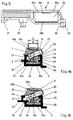
- the edge bar 4 shown in Fig. 2 of the drawing is made essentially from a stationary in the receiving groove 6 of the Hollow section spar 3a fixed fastening part 7 and out a handle 8, which with a bolt slide or Locking bar 9 through a plug-in coupling 10 into a detachable, but shear-proof connection can be brought.
- a latch engagement 11 attached to one Receiving opening 12 for the in the closed position
- Edge bolt 4 has protruding locking tongue 13.
- the hollow profile spar has 3a a two-stage receiving groove 6. This exists from an upper receiving groove 6a through upper and lower Last 6b and 6c is limited and one below Groove 6d. An undercut 14 is thereby made by the strip 6b formed in the upper receiving groove 6a, while the bar 6c an undercut 15 in the lower receiving groove 6d limited.
- FIGS. 4a and 4b a different dimensional design of the receiving groove 6a does not restrict the use of the fastening part 7.
- the clamping screw 20 needs a larger one Overcome the adjustment path to achieve the same effect, as in the narrow upper receiving groove 6a according to Fig. 4a.
- FIGS. 2 and 3 show the handle 8 together with the bolt slide 9 coupled to it in a thrust-resistant manner relative slidable to the fastening part 7.
- the Handle 8 one in the direction of their width as input and Passage for the fastening part 7 acting window-like Opening 21 on.
- the dimensional design of the window-like Opening 21 is made so that its guide width 22nd almost the guide width 23 of the fastening part 7 corresponds to, during their guide length 24 on the push path 25 of the locking slide or rod 9 is coordinated, such as Figures 2, 3 and 4a and 4b show.
- the plug coupling 10 is shown Embodiment of two pin-hole connections 28, 29 the pin-hole connection 28 in the area of bow-like longitudinal section 26 is arranged while the Pin-hole connection 28 in an upward cranked Section 30 of the locking slide 9 below the handle part 27 lies. This causes the entire handle 8 to twist prevented against the bolt slide 9.
- the entire handle 8 also has a higher stability through the upward bent portion 30 of the Latch slide 9.
- the window-like opening 21 is the Handle 8 provided with locking means 35a, 35b, which together with - not shown here - fastening part 7 for Fixing the sliding end positions of the handle 8 of the Latch slide 9 according to FIGS. 2 and 3 serve.
- the handle 8 has laterally projecting into the undercut 14 engaging strips 36, 37, like FIGS. 4a, 4b and 5 demonstrate. These ensure improved longitudinal guidance of the Handle 8 in the upper receiving groove 6a and prevent thereby also loosening the plug-in coupling 10.
- the guide the handle 8 is itself by the fastening part 7 guaranteed.
- the handle 8 is only on one side in the receiving groove 6a led, but the strips 36, 37 are based on the Last 6c of the hollow profile spar 3a.
- the handle 8 is a molded part made of elastic Hard plastic formed and has, as shown in FIG. 6 emerges, a longitudinally symmetrical shape. In the area of their window-like opening 21 it faces one Longitudinal cross-sectional plane 38 narrowing profile cross-section 39a, 39b, as can be seen in particular from FIGS. 4a and 4b.
- the profile cross section 39a, 39b is complementary designed longitudinal profile incisions 40a, 40b of the Fastening part 7 can be locked, thereby guiding the Handle 8 is secured in a simple manner.
Landscapes
- Engineering & Computer Science (AREA)
- Mechanical Engineering (AREA)
- Mutual Connection Of Rods And Tubes (AREA)
- Wing Frames And Configurations (AREA)
- Tents Or Canopies (AREA)
- Supports Or Holders For Household Use (AREA)
- Securing Of Glass Panes Or The Like (AREA)
- Connection Of Plates (AREA)
Applications Claiming Priority (2)
| Application Number | Priority Date | Filing Date | Title |
|---|---|---|---|
| DE29614649U DE29614649U1 (de) | 1996-08-23 | 1996-08-23 | Riegelbeschlag für Fenster, Türen o.dgl. mit zwei Flügeln |
| DE29614649U | 1996-08-23 |
Publications (2)
| Publication Number | Publication Date |
|---|---|
| EP0825317A1 true EP0825317A1 (fr) | 1998-02-25 |
| EP0825317B1 EP0825317B1 (fr) | 2000-07-26 |
Family
ID=8028246
Family Applications (1)
| Application Number | Title | Priority Date | Filing Date |
|---|---|---|---|
| EP97113947A Expired - Lifetime EP0825317B1 (fr) | 1996-08-23 | 1997-08-13 | Ferrure avec tige de verrouillage pour fenêtre, porte ou similaire, à deux vantaux |
Country Status (3)
| Country | Link |
|---|---|
| EP (1) | EP0825317B1 (fr) |
| DE (2) | DE29614649U1 (fr) |
| ES (1) | ES2150725T3 (fr) |
Families Citing this family (1)
| Publication number | Priority date | Publication date | Assignee | Title |
|---|---|---|---|---|
| CN118087976A (zh) * | 2024-03-27 | 2024-05-28 | 彭敏锋 | 一种新型双开门 |
Citations (3)
| Publication number | Priority date | Publication date | Assignee | Title |
|---|---|---|---|---|
| FR2467276A3 (fr) * | 1979-10-11 | 1981-04-17 | Technal International Sa | Perfectionnements aux targettes, notamment pour montage sur feuillure de vantail |
| FR2550573A1 (fr) * | 1983-08-13 | 1985-02-15 | Frank Gmbh Wilh | Mecanisme de fermeture du battant, couvert d'une fenetre ou d'une porte a deux battants sans montant central |
| US5328217A (en) * | 1992-04-30 | 1994-07-12 | Pemko Manufacturing Company | Locking astragal |
-
1996
- 1996-08-23 DE DE29614649U patent/DE29614649U1/de not_active Expired - Lifetime
-
1997
- 1997-08-13 EP EP97113947A patent/EP0825317B1/fr not_active Expired - Lifetime
- 1997-08-13 DE DE59702075T patent/DE59702075D1/de not_active Expired - Lifetime
- 1997-08-13 ES ES97113947T patent/ES2150725T3/es not_active Expired - Lifetime
Patent Citations (3)
| Publication number | Priority date | Publication date | Assignee | Title |
|---|---|---|---|---|
| FR2467276A3 (fr) * | 1979-10-11 | 1981-04-17 | Technal International Sa | Perfectionnements aux targettes, notamment pour montage sur feuillure de vantail |
| FR2550573A1 (fr) * | 1983-08-13 | 1985-02-15 | Frank Gmbh Wilh | Mecanisme de fermeture du battant, couvert d'une fenetre ou d'une porte a deux battants sans montant central |
| US5328217A (en) * | 1992-04-30 | 1994-07-12 | Pemko Manufacturing Company | Locking astragal |
Also Published As
| Publication number | Publication date |
|---|---|
| DE59702075D1 (de) | 2000-08-31 |
| DE29614649U1 (de) | 1996-10-02 |
| EP0825317B1 (fr) | 2000-07-26 |
| ES2150725T3 (es) | 2000-12-01 |
Similar Documents
| Publication | Publication Date | Title |
|---|---|---|
| DE2706013C2 (de) | Treibstangenbeschlag an Fenstern, Türen od.dgl. aus Metall- oder Kunststoffprofilen | |
| DE19846308C2 (de) | Abdicht- und Verriegelungsvorrichtung für Fenster oder Türen | |
| DE68902280T2 (de) | Verriegelungsbeschlag fuer schiebetueren, fenster o. dgl. | |
| DE8010921U1 (de) | Scharnierbandverbindung fuer fenster, tueren und tore | |
| EP0493689B1 (fr) | Tringlerie de commande pour fenêtres, portes ou similaires | |
| EP0152791A2 (fr) | Dispositif de manoeuvre pour panneaux coulissants de fenêtres, portes ou similaires | |
| EP0761920B1 (fr) | Fenêtre/porte avec battant pivotant et/ou basculant | |
| EP0748912A1 (fr) | Fenêtre, porte ou similaire | |
| EP0823522B1 (fr) | Engrenage à levier dans une feuillure pour fenêtres ou portes | |
| EP0833028B1 (fr) | Butée d'arrêt de glissière de guidage pour arrêt de fenêtre ou de porte | |
| EP0825317B1 (fr) | Ferrure avec tige de verrouillage pour fenêtre, porte ou similaire, à deux vantaux | |
| EP0733761B1 (fr) | Cadre de battant | |
| DE29804797U1 (de) | Fenster oder Tür | |
| DE19906071C2 (de) | Drehbegrenzer für Dreh-Schiebe-Fenster | |
| DE7901802U1 (de) | Schubriegel fuer fenster, tueren o.dgl. | |
| DE4200868A1 (de) | Zusatz-schliesseinrichtung fuer fenster | |
| EP0500125B1 (fr) | Dispositif de blocage pour fenêtres ou portes | |
| EP0445432A2 (fr) | Ferrure pour portes et fenêtres | |
| DE19857384C2 (de) | Befestigungsmittel zum Verbinden eines Flügelrahmens mit einem Blendrahmen zu einem nicht öffenbaren Fenster | |
| EP2362047B1 (fr) | Porte à levage coulissante ou fenêtre à levage coulissant | |
| EP0429981B1 (fr) | Ferrure arrangée en feuillure pour portes ou fenêtres oscillo-battantes, en particulier avec encadrement en bois | |
| EP0280950B1 (fr) | Strip de fermeture pour porte, fenêtre ou similaire | |
| EP0220391B1 (fr) | Dispositif de sécurité pour tringles de manoeuvre | |
| EP0672811A1 (fr) | Verrouillage de fausse manoeuvre pour une tringle de commande d'une fenêtre, d'une porte ou similaire | |
| DE2015723C3 (de) | Befestigung einer Eckumlenkung für Treibstangen von Treibstangenverschlüssen, insbesondere von Kipp-Schwenkflügel-Beschlägen, für Fenster, Türen o.dgl |
Legal Events
| Date | Code | Title | Description |
|---|---|---|---|
| PUAI | Public reference made under article 153(3) epc to a published international application that has entered the european phase |
Free format text: ORIGINAL CODE: 0009012 |
|
| AK | Designated contracting states |
Kind code of ref document: A1 Designated state(s): DE ES FR GB IT |
|
| AX | Request for extension of the european patent |
Free format text: AL;LT;LV;RO;SI |
|
| 17P | Request for examination filed |
Effective date: 19980311 |
|
| AKX | Designation fees paid |
Free format text: DE ES FR GB IT |
|
| RBV | Designated contracting states (corrected) |
Designated state(s): DE ES FR GB IT |
|
| GRAG | Despatch of communication of intention to grant |
Free format text: ORIGINAL CODE: EPIDOS AGRA |
|
| GRAG | Despatch of communication of intention to grant |
Free format text: ORIGINAL CODE: EPIDOS AGRA |
|
| GRAH | Despatch of communication of intention to grant a patent |
Free format text: ORIGINAL CODE: EPIDOS IGRA |
|
| 17Q | First examination report despatched |
Effective date: 19991217 |
|
| GRAH | Despatch of communication of intention to grant a patent |
Free format text: ORIGINAL CODE: EPIDOS IGRA |
|
| ITF | It: translation for a ep patent filed | ||
| GRAA | (expected) grant |
Free format text: ORIGINAL CODE: 0009210 |
|
| AK | Designated contracting states |
Kind code of ref document: B1 Designated state(s): DE ES FR GB IT |
|
| PG25 | Lapsed in a contracting state [announced via postgrant information from national office to epo] |
Ref country code: GB Free format text: LAPSE BECAUSE OF FAILURE TO SUBMIT A TRANSLATION OF THE DESCRIPTION OR TO PAY THE FEE WITHIN THE PRESCRIBED TIME-LIMIT Effective date: 20000726 |
|
| REF | Corresponds to: |
Ref document number: 59702075 Country of ref document: DE Date of ref document: 20000831 |
|
| ET | Fr: translation filed | ||
| REG | Reference to a national code |
Ref country code: ES Ref legal event code: FG2A Ref document number: 2150725 Country of ref document: ES Kind code of ref document: T3 |
|
| GBV | Gb: ep patent (uk) treated as always having been void in accordance with gb section 77(7)/1977 [no translation filed] |
Effective date: 20000726 |
|
| PLBE | No opposition filed within time limit |
Free format text: ORIGINAL CODE: 0009261 |
|
| STAA | Information on the status of an ep patent application or granted ep patent |
Free format text: STATUS: NO OPPOSITION FILED WITHIN TIME LIMIT |
|
| 26N | No opposition filed | ||
| PGFP | Annual fee paid to national office [announced via postgrant information from national office to epo] |
Ref country code: ES Payment date: 20100810 Year of fee payment: 14 |
|
| PGFP | Annual fee paid to national office [announced via postgrant information from national office to epo] |
Ref country code: FR Payment date: 20100901 Year of fee payment: 14 |
|
| REG | Reference to a national code |
Ref country code: FR Ref legal event code: ST Effective date: 20120430 |
|
| PG25 | Lapsed in a contracting state [announced via postgrant information from national office to epo] |
Ref country code: FR Free format text: LAPSE BECAUSE OF NON-PAYMENT OF DUE FEES Effective date: 20110831 |
|
| REG | Reference to a national code |
Ref country code: ES Ref legal event code: FD2A Effective date: 20130605 |
|
| PG25 | Lapsed in a contracting state [announced via postgrant information from national office to epo] |
Ref country code: ES Free format text: LAPSE BECAUSE OF NON-PAYMENT OF DUE FEES Effective date: 20110814 |
|
| PGFP | Annual fee paid to national office [announced via postgrant information from national office to epo] |
Ref country code: DE Payment date: 20150831 Year of fee payment: 19 |
|
| PGFP | Annual fee paid to national office [announced via postgrant information from national office to epo] |
Ref country code: IT Payment date: 20150831 Year of fee payment: 19 |
|
| REG | Reference to a national code |
Ref country code: DE Ref legal event code: R119 Ref document number: 59702075 Country of ref document: DE |
|
| PG25 | Lapsed in a contracting state [announced via postgrant information from national office to epo] |
Ref country code: DE Free format text: LAPSE BECAUSE OF NON-PAYMENT OF DUE FEES Effective date: 20170301 |
|
| PG25 | Lapsed in a contracting state [announced via postgrant information from national office to epo] |
Ref country code: IT Free format text: LAPSE BECAUSE OF NON-PAYMENT OF DUE FEES Effective date: 20160813 |