EP0833059A2 - Procédé de compression du gaz - Google Patents
Procédé de compression du gaz Download PDFInfo
- Publication number
- EP0833059A2 EP0833059A2 EP97115766A EP97115766A EP0833059A2 EP 0833059 A2 EP0833059 A2 EP 0833059A2 EP 97115766 A EP97115766 A EP 97115766A EP 97115766 A EP97115766 A EP 97115766A EP 0833059 A2 EP0833059 A2 EP 0833059A2
- Authority
- EP
- European Patent Office
- Prior art keywords
- compression
- gas
- pressure
- post
- mass flow
- Prior art date
- Legal status (The legal status is an assumption and is not a legal conclusion. Google has not performed a legal analysis and makes no representation as to the accuracy of the status listed.)
- Withdrawn
Links
Images
Classifications
-
- F—MECHANICAL ENGINEERING; LIGHTING; HEATING; WEAPONS; BLASTING
- F04—POSITIVE - DISPLACEMENT MACHINES FOR LIQUIDS; PUMPS FOR LIQUIDS OR ELASTIC FLUIDS
- F04D—NON-POSITIVE-DISPLACEMENT PUMPS
- F04D23/00—Other rotary non-positive-displacement pumps
- F04D23/001—Pumps adapted for conveying materials or for handling specific elastic fluids
- F04D23/003—Pumps adapted for conveying materials or for handling specific elastic fluids of radial-flow type
-
- F—MECHANICAL ENGINEERING; LIGHTING; HEATING; WEAPONS; BLASTING
- F04—POSITIVE - DISPLACEMENT MACHINES FOR LIQUIDS; PUMPS FOR LIQUIDS OR ELASTIC FLUIDS
- F04D—NON-POSITIVE-DISPLACEMENT PUMPS
- F04D27/00—Control, e.g. regulation, of pumps, pumping installations or pumping systems specially adapted for elastic fluids
- F04D27/02—Surge control
Definitions
- the invention relates to a method for compressing a gas with a constant Pressure, constant temperature and time-varying mass flow all in one constant final pressure through dynamic compression using a turbocompressor system, one plant for main compaction and one plant for post-compaction contains.
- Methods according to the preamble of claim 1 are from the publications of Guy Gisteau-Baguer, "High Power Refrigeration at Temperatures Around 2 K", ICEC (International Cryogenic Engineering Conference) 16, 1996, Kitakyushu, Japan, and by M.Kauschke, C.Haberstroh, H.Quack “Safe and Efficient Operation of Multistage Cold Compressor Systems ", CEC (Cryogenic Engineering Conference) 1995 Columbus, USA, known.
- High-performance cryogenic refrigeration systems are used on particle accelerators in nuclear research facilities, which are required for cooling superconducting magnets and cavity resonators.
- the vapor pressure of helium at 2 K is 3129 Pa (31 mbar).
- helium must be compressed from 31 mbar to atmospheric pressure. This corresponds to a compression ratio of 32: 1.
- turbocompressors are used for the compression of the large mass flows that occur with high cooling capacity. Usually up to five compressor stages are required.
- Cold compressors are used in order to be able to use smaller turbocompressors with a correspondingly low volume flow, and the higher density at low temperatures also permits high pressure ratios per stage.
- the heat exchanger which heats the gas to ambient temperatures, can be made much simpler.
- turbocompressors are limited a variation of the gas inlet temperature and the mass flow with stable operation enable all compressor stages. This is in contrast to the most requested Operating modes with reduced cooling capacity, with fast load changes and with Chilling the refrigeration system. Changes in the final pressure are common, even at far under atmospheric pressure. This can be in the warm part of the refrigeration system lead to undesired inflow of air into the refrigeration cycle. Become frequent volumetric compressors are also used, which have an increased load at part load Take over pressure ratio, but only suitable for a limited mass flow are. Or the smaller mass flow with reduced cooling capacity is reduced by one additional mass flow supplements, resulting in poor overall efficiency Refrigeration system.
- the object of the invention is therefore to largely avoid these disadvantages.
- the dynamic compression in a turbocompressor system is carried out so that the gas at maximum mass flow reaches the final pressure in the main compression and bypasses the post-compression is used for further use.
- the advantage is the required To achieve final pressure in a main operating case in a thermodynamically favorable manner, where the post-compression need not be in operation. With one opposite the maximum mass flow reduced mass flow, the gas is in the Post-compression passed, there compressed to the final pressure and then for further use fed.
- the advantage is that the procedure is important for one Part load case can also be designed and operated thermodynamically favorable.
- the post-compression compresses the pressure over a certain pressure ratio Final pressure. The machines connected below with regard to the pressures suck at lower ones To press.
- the method according to the invention can be used advantageously if that too compressing gas is present at cryogenic temperatures. Warming up before compression requires additional heat exchangers combined with a warm compressor, which must then be much larger because of the larger volume flow.
- the method according to the invention can be used advantageously if the pressure of the gas to be compressed in the vacuum range between the boiling pressure of the gas and the atmospheric pressure.
- this pressure range with principally high ones
- volume flows are the area of application through least limited available size of the compressors.
- the multi-stage execution of the main compression of the method according to the invention enables, especially when using intercoolers, an improvement in Efficiency of compression.
- the post-compression can be carried out with only one compressor stage be performed.
- the additional investment for operation at part load is then particularly low.
- the turbocompressor system can advantageously in the method according to the invention between successive turbocompressor stages intermediate cooler or reheater contain. This allows the operation of the system through adjustment and Temperature regulation can be kept stable. With intercooling can also the number of turbocompressor stages required for economical operation and whose size can be reduced. In addition, the thermodynamic improves Efficiency of the compression system.
- the main compression preferably the first stage of the multi-stage version Main compression, can be advantageous in the method according to the invention with a speed control be equipped. This enables, especially when operating with more than two modes of operation, during load changes and dynamic Operation setting and control to a constant final pressure.
- the gas to be compressed can also be helium in the process according to the invention.
- This gas can be used, in particular, when using the method in a helium refrigeration system or in a helium liquefaction plant during compression both very low initial temperatures as well as very low initial pressures occur for which, as described above, the method according to the invention is particularly useful well suited.
- the disadvantages, as in the case of methods according to the prior art technology have occurred in the same application.
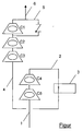
- the invention is explained in more detail using an embodiment with a figure.
- the Figure shows schematically the execution of the method according to the invention using the example an application in a helium refrigeration system.
- the method is part of a helium refrigeration system, not shown in the figure, and is designed as a turbo compressor system. It consists of a main compression C1 to C4 with intermediate cooling 3 after the turbocompressor stage C2, a post-compression with the turbocompressor stage C5 and a bypass 6 of this stage C5.
- the cryogenic Helium stream 1 arrives with a mass flow of 100 g / s at a pressure of 31 mbar and a temperature of 2 K in the first turbocompressor stage C1, then in the second turbocompressor stage C2 and via line 2 at an intermediate pressure of about 6 mbar in the intercooler 3, with the help of which also a stable intermediate temperature can be adjusted.
- the helium stream 4 becomes the third and fourth turbocompressor stages C3 and C4, compressed to a final pressure of 1 bar, via the bypass 5 at the post-compression with the turbocompressor stage C5 passed and, what is not shown in the figure, as a helium stream 6 to the refrigeration circuit fed to the helium refrigeration system.
- a partial load operation with a mass flow of 80 g / s corresponds to the operating characteristics of the turbo compressor stages C1 and C2 in the helium stream 4 a reduced intermediate pressure of ⁇ 6 mbar.
- a pressure of ⁇ 1 bar is reached in the turbocompressor stages C3 and C4 and in the Turbo compressor stage C5 compresses the helium flow to the final pressure of 1 bar.
- the first turbocompression stage C1 of the main compression is with a speed control equipped.
- the transition to partial load operation and dynamic Operation of the helium refrigeration system the constant final pressure of the helium flow 6 regulated to 1 bar.
Landscapes
- Engineering & Computer Science (AREA)
- Mechanical Engineering (AREA)
- General Engineering & Computer Science (AREA)
- Separation By Low-Temperature Treatments (AREA)
- Control Of Positive-Displacement Pumps (AREA)
Applications Claiming Priority (2)
| Application Number | Priority Date | Filing Date | Title |
|---|---|---|---|
| DE19639733 | 1996-09-27 | ||
| DE1996139733 DE19639733A1 (de) | 1996-09-27 | 1996-09-27 | Verfahren zum Verdichten eines Gases |
Publications (2)
| Publication Number | Publication Date |
|---|---|
| EP0833059A2 true EP0833059A2 (fr) | 1998-04-01 |
| EP0833059A3 EP0833059A3 (fr) | 1998-11-11 |
Family
ID=7807071
Family Applications (1)
| Application Number | Title | Priority Date | Filing Date |
|---|---|---|---|
| EP97115766A Withdrawn EP0833059A3 (fr) | 1996-09-27 | 1997-09-10 | Procédé de compression du gaz |
Country Status (3)
| Country | Link |
|---|---|
| EP (1) | EP0833059A3 (fr) |
| JP (1) | JPH10111032A (fr) |
| DE (1) | DE19639733A1 (fr) |
Cited By (1)
| Publication number | Priority date | Publication date | Assignee | Title |
|---|---|---|---|---|
| EP1441128A3 (fr) * | 2003-01-24 | 2004-09-01 | Pfeiffer Vacuum GmbH | Système de pompe à vide |
Families Citing this family (1)
| Publication number | Priority date | Publication date | Assignee | Title |
|---|---|---|---|---|
| DE102014010102A1 (de) * | 2014-07-08 | 2016-01-14 | Linde Aktiengesellschaft | Verfahren zur Druck- und Temperaturreglung eines Fluids in einer Serie von kryogenen Verdichtern |
Family Cites Families (4)
| Publication number | Priority date | Publication date | Assignee | Title |
|---|---|---|---|---|
| BE370856A (fr) * | ||||
| US1465401A (en) * | 1921-03-31 | 1923-08-21 | Losel Franz | Turbocompressor |
| US1519449A (en) * | 1923-05-14 | 1924-12-16 | Escher Wyss Maschf Ag | Compressor installation |
| CH347296A (de) * | 1957-02-01 | 1960-06-30 | Escher Wyss Ag | Einrichtung zur Verbesserung des Teillastbetriebes einer Turboverdichteranlage |
-
1996
- 1996-09-27 DE DE1996139733 patent/DE19639733A1/de not_active Withdrawn
-
1997
- 1997-09-10 EP EP97115766A patent/EP0833059A3/fr not_active Withdrawn
- 1997-09-24 JP JP27498897A patent/JPH10111032A/ja active Pending
Cited By (1)
| Publication number | Priority date | Publication date | Assignee | Title |
|---|---|---|---|---|
| EP1441128A3 (fr) * | 2003-01-24 | 2004-09-01 | Pfeiffer Vacuum GmbH | Système de pompe à vide |
Also Published As
| Publication number | Publication date |
|---|---|
| EP0833059A3 (fr) | 1998-11-11 |
| DE19639733A1 (de) | 1998-04-16 |
| JPH10111032A (ja) | 1998-04-28 |
Similar Documents
| Publication | Publication Date | Title |
|---|---|---|
| DE2800742C2 (de) | Vorrichtung zum Erzeugen von Kälte oder zum Verflüssigen von Gasen | |
| DE69510728T2 (de) | Kühlverfahren und -system | |
| EP0093448B1 (fr) | Procédé et dispositif pour obtenir de l'oxygène gazeux sous pression élevée | |
| EP0316768B1 (fr) | Procédé de séparation d'air par rectification à basse température | |
| WO2006018389A1 (fr) | Procede de production d'energie dans une installation de production d'energie comprenant une turbine a gaz et installation de production d'energie appropriee pour mettre ledit procede en oeuvre | |
| DE69201522T2 (de) | Hochdruck-Lufttrennungsverfahren mit Gewinnung von Flüssigkeit. | |
| EP2980514A1 (fr) | Procédé de séparation cryogénique de l'air et installation de séparation d'air | |
| DE1259914B (de) | Verfahren zur Verfluessigung von Helium | |
| EP1719650B1 (fr) | Climatisation pour véhicule | |
| DE2730155C3 (de) | Verfahren zum Erzeugen von Kälte im Bereich kryogener Temperaturen | |
| DE3429420C2 (fr) | ||
| EP0592059A1 (fr) | Procédé et dispositif pour comprimer un gaz | |
| DE69514936T2 (de) | Kühlsystem und verfahren | |
| DE102004005305A1 (de) | Verfahren zum Rückverflüssigen eines Gases | |
| DE19639733A1 (de) | Verfahren zum Verdichten eines Gases | |
| DE102011012644A1 (de) | Kälteanlage | |
| DE19755484A1 (de) | Verfahren zur Kälteerzeugung im Temperaturbereich von 50,1 bis 63 Kelvin und Vorrichtung zur Durchführung dieses Verfahrens | |
| DE19718092A1 (de) | Verfahren zur Verdichtung eines Gases bei niedriger Temperatur und bei niedrigem Druck, entsprechende Verdichtungsleitung und Kühlanlage | |
| EP3870916B1 (fr) | Procédé de production d'un produit ou d'une pluralité de produits de l'air et installation de séparation de l'air | |
| DE2049181B2 (de) | Verfahren zur Kälteerzeugung durch Kompression eines Gemisches von verschiedenen Kältemitteln mit unterschiedlichen Siedepunkten | |
| EP3293475A1 (fr) | Procédé et appareil de stockage et de récupération d'énergie | |
| DE10147047A1 (de) | Zwei-oder Drei-Turbinen-Kreislauf zur Erzeugung eines Flüssigkeitsprodukts | |
| DE2636933A1 (de) | Verfahren zum abkuehlen und verfluessigen eines tiefsiedenden gases | |
| DE19748966B4 (de) | Vorrichtung und Verfahren zur Herstellung und Lagerung von flüssiger Luft | |
| DE19525638C2 (de) | Kühlverfahren mittels tiefsiedender Gase und Vorrichtung zur Durchführung des Verfahrens |
Legal Events
| Date | Code | Title | Description |
|---|---|---|---|
| PUAI | Public reference made under article 153(3) epc to a published international application that has entered the european phase |
Free format text: ORIGINAL CODE: 0009012 |
|
| AK | Designated contracting states |
Kind code of ref document: A2 Designated state(s): AT CH DE FR GB IT LI NL |
|
| AX | Request for extension of the european patent |
Free format text: AL;LT;LV;RO;SI |
|
| PUAL | Search report despatched |
Free format text: ORIGINAL CODE: 0009013 |
|
| AK | Designated contracting states |
Kind code of ref document: A3 Designated state(s): AT BE CH DE DK ES FI FR GB GR IE IT LI LU MC NL PT SE |
|
| AX | Request for extension of the european patent |
Free format text: AL;LT;LV;RO;SI |
|
| 17P | Request for examination filed |
Effective date: 19981118 |
|
| AKX | Designation fees paid |
Free format text: AT CH DE FR GB IT LI NL |
|
| STAA | Information on the status of an ep patent application or granted ep patent |
Free format text: STATUS: THE APPLICATION IS DEEMED TO BE WITHDRAWN |
|
| 18D | Application deemed to be withdrawn |
Effective date: 20010403 |