EP0834877A2 - Plattenantriebsvorrichtung - Google Patents
Plattenantriebsvorrichtung Download PDFInfo
- Publication number
- EP0834877A2 EP0834877A2 EP97307464A EP97307464A EP0834877A2 EP 0834877 A2 EP0834877 A2 EP 0834877A2 EP 97307464 A EP97307464 A EP 97307464A EP 97307464 A EP97307464 A EP 97307464A EP 0834877 A2 EP0834877 A2 EP 0834877A2
- Authority
- EP
- European Patent Office
- Prior art keywords
- disk
- centering
- turntable
- portions
- driving device
- Prior art date
- Legal status (The legal status is an assumption and is not a legal conclusion. Google has not performed a legal analysis and makes no representation as to the accuracy of the status listed.)
- Granted
Links
- 230000002093 peripheral effect Effects 0.000 claims description 22
- XEEYBQQBJWHFJM-UHFFFAOYSA-N Iron Chemical compound [Fe] XEEYBQQBJWHFJM-UHFFFAOYSA-N 0.000 description 6
- 239000000853 adhesive Substances 0.000 description 6
- 230000001070 adhesive effect Effects 0.000 description 6
- 238000005452 bending Methods 0.000 description 3
- 229910052742 iron Inorganic materials 0.000 description 3
- 239000000463 material Substances 0.000 description 3
- 229910000906 Bronze Inorganic materials 0.000 description 2
- OAICVXFJPJFONN-UHFFFAOYSA-N Phosphorus Chemical compound [P] OAICVXFJPJFONN-UHFFFAOYSA-N 0.000 description 2
- 239000010974 bronze Substances 0.000 description 2
- KUNSUQLRTQLHQQ-UHFFFAOYSA-N copper tin Chemical compound [Cu].[Sn] KUNSUQLRTQLHQQ-UHFFFAOYSA-N 0.000 description 2
- 230000000630 rising effect Effects 0.000 description 2
- 229910000859 α-Fe Inorganic materials 0.000 description 2
- 229910001369 Brass Inorganic materials 0.000 description 1
- 206010010071 Coma Diseases 0.000 description 1
- 230000005856 abnormality Effects 0.000 description 1
- 239000002390 adhesive tape Substances 0.000 description 1
- 239000010951 brass Substances 0.000 description 1
- 238000004519 manufacturing process Methods 0.000 description 1
- 230000004048 modification Effects 0.000 description 1
- 238000012986 modification Methods 0.000 description 1
- 230000035939 shock Effects 0.000 description 1
- 229920003002 synthetic resin Polymers 0.000 description 1
- 239000000057 synthetic resin Substances 0.000 description 1
Images




Classifications
-
- G—PHYSICS
- G11—INFORMATION STORAGE
- G11B—INFORMATION STORAGE BASED ON RELATIVE MOVEMENT BETWEEN RECORD CARRIER AND TRANSDUCER
- G11B17/00—Guiding record carriers not specifically of filamentary or web form, or of supports therefor
- G11B17/02—Details
- G11B17/022—Positioning or locking of single discs
- G11B17/028—Positioning or locking of single discs of discs rotating during transducing operation
- G11B17/0282—Positioning or locking of single discs of discs rotating during transducing operation by means provided on the turntable
-
- G—PHYSICS
- G11—INFORMATION STORAGE
- G11B—INFORMATION STORAGE BASED ON RELATIVE MOVEMENT BETWEEN RECORD CARRIER AND TRANSDUCER
- G11B19/00—Driving, starting, stopping record carriers not specifically of filamentary or web form, or of supports therefor; Control thereof; Control of operating function ; Driving both disc and head
- G11B19/20—Driving; Starting; Stopping; Control thereof
-
- G—PHYSICS
- G11—INFORMATION STORAGE
- G11B—INFORMATION STORAGE BASED ON RELATIVE MOVEMENT BETWEEN RECORD CARRIER AND TRANSDUCER
- G11B17/00—Guiding record carriers not specifically of filamentary or web form, or of supports therefor
- G11B17/02—Details
- G11B17/022—Positioning or locking of single discs
- G11B17/028—Positioning or locking of single discs of discs rotating during transducing operation
- G11B17/0284—Positioning or locking of single discs of discs rotating during transducing operation by clampers
-
- G—PHYSICS
- G11—INFORMATION STORAGE
- G11B—INFORMATION STORAGE BASED ON RELATIVE MOVEMENT BETWEEN RECORD CARRIER AND TRANSDUCER
- G11B19/00—Driving, starting, stopping record carriers not specifically of filamentary or web form, or of supports therefor; Control thereof; Control of operating function ; Driving both disc and head
- G11B19/20—Driving; Starting; Stopping; Control thereof
- G11B19/2009—Turntables, hubs and motors for disk drives; Mounting of motors in the drive
Definitions
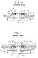
- a spindle motor (not shown) causes rotation of a rotor yoke 11, which causes rotation of a turntable 13 having mounted thereto a rotary shaft 12 by press-fitting or the like.
- the turntable 13 is made of brass that is subjected to turning or the like.
- a cylindrical portion 13a is formed around the center portion of the turntable 13, with the aforementioned rotary shaft 12 press-fitted and secured to the center of the cylindrical portion 13a.
- a disk-shaped flange 13b is formed at the outer peripheral side of the cylindrical portion 13a, and has a flat surface having affixed thereto with an adhesive tape an anti-slipping sheet 14 serving as the disk-mounting surface.
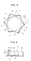
- Fig. 4 is a plan view of the centering member in accordance with the present invention.
- Fig. 5 is a partial enlarged view of the centering portion of the centering member in accordance with the present invention.
- Fig. 6 is a sectionai view of the main portion of the centering member and the turntable in accordance with the present invention to illustrate the relationship therebetween.
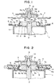
- Positioning holes 4g are formed at a plurality of locations at equal intervals so as to be disposed at the inner peripheral side of the flange 4a.
- the protrusions 1b are fitted into the positioning holes 4g to position the rotor yoke 1 and the turntable 4 in order to affix them together with an adhesive or the like.
- each positioning portion S3 contacts one of the side walls 4f of the associated centering window 4d of the turntable 4.
- Each supporting portion 5a formed by vertically bending a portion of its associated centering portion 5, contacts and is positioned at the inner wall of the cylindrical portion 4b of the turntable 4 at a predetermined location in order to be mounted onto the upper surface of the rotor yoke 1.
- the plurality of first protruding strip portions 5e are resiliently biased with a force exerted outwardly and horizontally in the direction of the surface of the flange 4a that is the disk D mounting surface (or in the direction of arrow B), so that its center hole D1 is uniformly resiliently pressed, whereby centering of the disk D is performed.
- Anti-slipping sheets 6 are bonded at equal intervals at a plurality of locations along the upper surface of the peripheral edge of the flange 4a that provides the disk mounting surface of the turntable 4 in order to prevent slipping of the disk D loaded onto the turntable 4.
- a second attraction magnet 8 composed of a sintered ferrite material, is affixed using an adhesive or the like to a surface of the ceiling 7d in the hat-shaped interior of the cylindrical portion 7b.
- the center portion of the ceiling 7d has a center hole 8a extending therethrough.
- An alignment shaft 9 which is coma-shaped in appearance is fitted into the center hole 8a, and includes an alignment portion 9a at an end thereof and a taper 9b at its base. The alignment portion 9a and the taper 9b protrude downwardly from a lower surface 9c of the second attraction magnet 8.
- the press-contacting force of the flange 7a of the clamper 7 used for chucking the disk D adjusts the magnetic force of the first and second attraction magnets 3 and 8 to a predetermined strength, thereby preventing the disk D from being scratched or deformed from the press-contacting by the flange 7a of the clamper 7.
- the centering member includes a supporting portion and a centering portion extending from the supporting portion in the direction of the disk-mounting surface of the turntable, so that the centering portion is resiliently biased outwardly and horizontally in the direction of the disk-mounting surface of the turntable to center the disk. Therefore, only an outward and horizontal force is exerted onto the center hole of the disk, which prevents the disk from tilting, or the disk from rising from the disk-mounting surface of the turntable.
- the centering portion has a protruding strip portion extending perpendicular to the disk-mounting surface of the turntable, when the disk is centered, the protruding strip portion is resiliently pressed against the inner peripheral surface of the center hole of the disk in a direction of the plate thickness, reducing the area of contact between the center hole and the centering portion. This reduces the frictional resistance between the center hole and the centering portion during loading of the disk onto the turntable, allowing the disk to be smoothly loaded onto the disk-loading surface of the turntable, thereby preventing the disk from tilting or the disk from rising from the disk-mounting surface.
Landscapes
- Holding Or Fastening Of Disk On Rotational Shaft (AREA)
Applications Claiming Priority (3)
| Application Number | Priority Date | Filing Date | Title |
|---|---|---|---|
| JP8281486A JPH10112099A (ja) | 1996-10-02 | 1996-10-02 | ディスク駆動装置 |
| JP281486/96 | 1996-10-02 | ||
| JP28148696 | 1996-10-02 |
Publications (3)
| Publication Number | Publication Date |
|---|---|
| EP0834877A2 true EP0834877A2 (de) | 1998-04-08 |
| EP0834877A3 EP0834877A3 (de) | 1998-12-16 |
| EP0834877B1 EP0834877B1 (de) | 2004-06-16 |
Family
ID=17639866
Family Applications (1)
| Application Number | Title | Priority Date | Filing Date |
|---|---|---|---|
| EP97307464A Expired - Lifetime EP0834877B1 (de) | 1996-10-02 | 1997-09-24 | Plattenantriebsvorrichtung |
Country Status (6)
| Country | Link |
|---|---|
| US (1) | US6108294A (de) |
| EP (1) | EP0834877B1 (de) |
| JP (1) | JPH10112099A (de) |
| KR (1) | KR100258227B1 (de) |
| DE (1) | DE69729522T2 (de) |
| TW (1) | TW432356B (de) |
Cited By (1)
| Publication number | Priority date | Publication date | Assignee | Title |
|---|---|---|---|---|
| EP1783762A3 (de) * | 2005-08-22 | 2009-01-07 | Funai Electric Co., Ltd. | Optisches Plattenlaufwerk |
Families Citing this family (14)
| Publication number | Priority date | Publication date | Assignee | Title |
|---|---|---|---|---|
| TW522390B (en) * | 1998-07-09 | 2003-03-01 | Ind Tech Res Inst | Magnet-floating auto-elevating disk clamper tool |
| JP2001236708A (ja) * | 2000-02-22 | 2001-08-31 | Shinano Kenshi Co Ltd | ディスククランプ機構 |
| KR100418424B1 (ko) * | 2000-07-12 | 2004-02-14 | 디브이에스 코리아 주식회사 | 디스크의 클램핑장치 |
| JP3075218U (ja) * | 2000-07-28 | 2001-02-16 | 東英工業株式会社 | 光磁気ディスク記録装置におけるローディング装置 |
| US6570835B1 (en) * | 2001-02-15 | 2003-05-27 | Eutronic Technology Company Ltd. | Support structure for compact disc |
| JP2002312999A (ja) * | 2001-04-16 | 2002-10-25 | Mitsumi Electric Co Ltd | ディスク装置 |
| JP2002358706A (ja) * | 2001-05-31 | 2002-12-13 | Tokyo Parts Ind Co Ltd | ディスククランプ機構及びこのディスククランプ機構を備えたディスク駆動装置 |
| TW505296U (en) * | 2001-10-12 | 2002-10-01 | Lite On It Corp | Reed type clamping device |
| JP2005038465A (ja) * | 2003-07-15 | 2005-02-10 | Toshiba Corp | ディスク支持機構および光ディスク装置 |
| KR101135283B1 (ko) | 2009-10-08 | 2012-04-12 | 엘지이노텍 주식회사 | 스핀들 모터 |
| KR20110085028A (ko) * | 2010-01-19 | 2011-07-27 | 삼성전자주식회사 | 데이터 저장장치용 디스크 스페이서 및 그를 구비하는 하드디스크 드라이브 |
| KR101101516B1 (ko) * | 2010-04-23 | 2012-01-04 | 삼성전기주식회사 | 디스크 척킹 장치, 모터 및 이를 탑재한 디스크 구동 장치 |
| KR20120082199A (ko) | 2011-01-13 | 2012-07-23 | 엘지이노텍 주식회사 | 스핀들 모터용 턴 테이블 및 이를 갖는 스핀들 모터 |
| DE102014107080A1 (de) * | 2014-05-20 | 2015-11-26 | Ecs Engineered Control Systems Ag | Haltevorrichtung sowie Stift zur Anordnung in einer solchen Haltevorrichtung |
Family Cites Families (9)
| Publication number | Priority date | Publication date | Assignee | Title |
|---|---|---|---|---|
| US4562570A (en) * | 1983-11-28 | 1985-12-31 | North American Philips Consumer Electronics Corp. | Video disc turntable having clamping device |
| NL8403582A (nl) * | 1984-11-26 | 1986-06-16 | Philips Nv | Inrichting voor het centreren, richten en vastklemmen van een optische plaat. |
| JPH0418103Y2 (de) * | 1985-06-05 | 1992-04-22 | ||
| US5050159A (en) * | 1987-12-15 | 1991-09-17 | Pioneer Electronic Corporation | Double-sides playable disc player |
| US5006945A (en) * | 1989-02-22 | 1991-04-09 | Pioneer Electronic Corp. | Disk player having dual-side playback capability |
| JP2861144B2 (ja) * | 1989-11-16 | 1999-02-24 | ソニー株式会社 | ディスクチャッキング機構 |
| JP3384002B2 (ja) * | 1992-01-24 | 2003-03-10 | ソニー株式会社 | ディスクテーブル及び記録及び/又は再生装置 |
| JPH06131783A (ja) * | 1992-10-19 | 1994-05-13 | Asahi Corp:Kk | ディスク保持装置 |
| JPH08195010A (ja) * | 1995-01-13 | 1996-07-30 | Matsushita Electric Ind Co Ltd | ディスクセンタリング装置 |
-
1996
- 1996-10-02 JP JP8281486A patent/JPH10112099A/ja active Pending
-
1997
- 1997-09-24 DE DE69729522T patent/DE69729522T2/de not_active Expired - Fee Related
- 1997-09-24 TW TW086113929A patent/TW432356B/zh not_active IP Right Cessation
- 1997-09-24 EP EP97307464A patent/EP0834877B1/de not_active Expired - Lifetime
- 1997-10-01 US US08/941,969 patent/US6108294A/en not_active Expired - Fee Related
- 1997-10-02 KR KR1019970050986A patent/KR100258227B1/ko not_active Expired - Fee Related
Cited By (1)
| Publication number | Priority date | Publication date | Assignee | Title |
|---|---|---|---|---|
| EP1783762A3 (de) * | 2005-08-22 | 2009-01-07 | Funai Electric Co., Ltd. | Optisches Plattenlaufwerk |
Also Published As
| Publication number | Publication date |
|---|---|
| EP0834877A3 (de) | 1998-12-16 |
| DE69729522T2 (de) | 2004-10-14 |
| DE69729522D1 (de) | 2004-07-22 |
| EP0834877B1 (de) | 2004-06-16 |
| KR19980032526A (ko) | 1998-07-25 |
| KR100258227B1 (ko) | 2000-07-01 |
| US6108294A (en) | 2000-08-22 |
| TW432356B (en) | 2001-05-01 |
| JPH10112099A (ja) | 1998-04-28 |
Similar Documents
| Publication | Publication Date | Title |
|---|---|---|
| US6108294A (en) | Disk driving device with small centering force variation | |
| KR100529437B1 (ko) | 디스크 유지 장치 | |
| US8334625B2 (en) | Method for manufacturing a storage disk drive motor, motor for driving a storage disk and storage disk drive apparatus provided with the motor | |
| US4920437A (en) | Disc clamping device | |
| JP2000067497A (ja) | モータのディスクチャッキング機構 | |
| CN1656551A (zh) | 芯轴马达 | |
| US6072767A (en) | Turntable device for an optical disk | |
| KR20010023818A (ko) | 디스크 장치의 디스크 클램프 기구 | |
| JP2000163839A (ja) | ディスク装置のディスククランプ機構 | |
| JP2000132893A (ja) | モ―タのディスクチャッキング機構 | |
| JP3558785B2 (ja) | ターンテーブル付スピンドルモータ | |
| KR100370792B1 (ko) | 모터의 디스크척킹 기구 | |
| JP2002329356A (ja) | チャッキング装置 | |
| JPH09326147A (ja) | ディスクプレーヤーのディスククランピング装置 | |
| JP3629824B2 (ja) | モータ | |
| JPH09106600A (ja) | コンパクトディスクプレーヤーのディスクチャッキング装置 | |
| JPH0713075Y2 (ja) | ディスククランプ機構 | |
| JPH0845222A (ja) | ディスク用アダプタ | |
| JP2004030744A (ja) | スピンドルモータのクランプ機構 | |
| JPH04117661A (ja) | ディスク駆動装置のチャッキング機構 | |
| KR100297750B1 (ko) | 디스크플레이어의디스크클램핑장치 | |
| JPH0627015Y2 (ja) | ディスククランプ機構 | |
| JPH10106091A (ja) | ディスク駆動装置 | |
| JP2000251361A (ja) | ディスク駆動装置 | |
| JPH0627014Y2 (ja) | ディスクの回転駆動装置 |
Legal Events
| Date | Code | Title | Description |
|---|---|---|---|
| PUAI | Public reference made under article 153(3) epc to a published international application that has entered the european phase |
Free format text: ORIGINAL CODE: 0009012 |
|
| AK | Designated contracting states |
Kind code of ref document: A2 Designated state(s): DE FR GB NL |
|
| AX | Request for extension of the european patent |
Free format text: AL;LT;LV;RO;SI |
|
| PUAL | Search report despatched |
Free format text: ORIGINAL CODE: 0009013 |
|
| AK | Designated contracting states |
Kind code of ref document: A3 Designated state(s): AT BE CH DE DK ES FI FR GB GR IE IT LI LU MC NL PT SE |
|
| AX | Request for extension of the european patent |
Free format text: AL;LT;LV;RO;SI |
|
| 17P | Request for examination filed |
Effective date: 19981230 |
|
| AKX | Designation fees paid |
Free format text: DE FR GB NL |
|
| 17Q | First examination report despatched |
Effective date: 20020805 |
|
| GRAP | Despatch of communication of intention to grant a patent |
Free format text: ORIGINAL CODE: EPIDOSNIGR1 |
|
| GRAS | Grant fee paid |
Free format text: ORIGINAL CODE: EPIDOSNIGR3 |
|
| GRAA | (expected) grant |
Free format text: ORIGINAL CODE: 0009210 |
|
| AK | Designated contracting states |
Kind code of ref document: B1 Designated state(s): DE FR GB NL |
|
| PG25 | Lapsed in a contracting state [announced via postgrant information from national office to epo] |
Ref country code: NL Free format text: LAPSE BECAUSE OF FAILURE TO SUBMIT A TRANSLATION OF THE DESCRIPTION OR TO PAY THE FEE WITHIN THE PRESCRIBED TIME-LIMIT Effective date: 20040616 |
|
| REG | Reference to a national code |
Ref country code: GB Ref legal event code: FG4D |
|
| REF | Corresponds to: |
Ref document number: 69729522 Country of ref document: DE Date of ref document: 20040722 Kind code of ref document: P |
|
| PGFP | Annual fee paid to national office [announced via postgrant information from national office to epo] |
Ref country code: GB Payment date: 20040817 Year of fee payment: 8 |
|
| PGFP | Annual fee paid to national office [announced via postgrant information from national office to epo] |
Ref country code: FR Payment date: 20040921 Year of fee payment: 8 |
|
| PGFP | Annual fee paid to national office [announced via postgrant information from national office to epo] |
Ref country code: DE Payment date: 20041129 Year of fee payment: 8 |
|
| NLV1 | Nl: lapsed or annulled due to failure to fulfill the requirements of art. 29p and 29m of the patents act | ||
| ET | Fr: translation filed | ||
| PLBE | No opposition filed within time limit |
Free format text: ORIGINAL CODE: 0009261 |
|
| STAA | Information on the status of an ep patent application or granted ep patent |
Free format text: STATUS: NO OPPOSITION FILED WITHIN TIME LIMIT |
|
| 26N | No opposition filed |
Effective date: 20050317 |
|
| PG25 | Lapsed in a contracting state [announced via postgrant information from national office to epo] |
Ref country code: GB Free format text: LAPSE BECAUSE OF NON-PAYMENT OF DUE FEES Effective date: 20050924 |
|
| PG25 | Lapsed in a contracting state [announced via postgrant information from national office to epo] |
Ref country code: DE Free format text: LAPSE BECAUSE OF NON-PAYMENT OF DUE FEES Effective date: 20060401 |
|
| GBPC | Gb: european patent ceased through non-payment of renewal fee |
Effective date: 20050924 |
|
| PG25 | Lapsed in a contracting state [announced via postgrant information from national office to epo] |
Ref country code: FR Free format text: LAPSE BECAUSE OF NON-PAYMENT OF DUE FEES Effective date: 20060531 |
|
| REG | Reference to a national code |
Ref country code: FR Ref legal event code: ST Effective date: 20060531 |