EP0874193A2 - Methode und Vorrichtung zur Erzeugung von trockenem Dampf - Google Patents
Methode und Vorrichtung zur Erzeugung von trockenem Dampf Download PDFInfo
- Publication number
- EP0874193A2 EP0874193A2 EP98113092A EP98113092A EP0874193A2 EP 0874193 A2 EP0874193 A2 EP 0874193A2 EP 98113092 A EP98113092 A EP 98113092A EP 98113092 A EP98113092 A EP 98113092A EP 0874193 A2 EP0874193 A2 EP 0874193A2
- Authority
- EP
- European Patent Office
- Prior art keywords
- block
- vessel
- liquid
- vapor
- settling chamber
- Prior art date
- Legal status (The legal status is an assumption and is not a legal conclusion. Google has not performed a legal analysis and makes no representation as to the accuracy of the status listed.)
- Granted
Links
Images


Classifications
-
- B—PERFORMING OPERATIONS; TRANSPORTING
- B01—PHYSICAL OR CHEMICAL PROCESSES OR APPARATUS IN GENERAL
- B01D—SEPARATION
- B01D1/00—Evaporating
- B01D1/30—Accessories for evaporators ; Constructional details thereof
- B01D1/305—Demister (vapour-liquid separation)
-
- H—ELECTRICITY
- H10—SEMICONDUCTOR DEVICES; ELECTRIC SOLID-STATE DEVICES NOT OTHERWISE PROVIDED FOR
- H10P—GENERIC PROCESSES OR APPARATUS FOR THE MANUFACTURE OR TREATMENT OF DEVICES COVERED BY CLASS H10
- H10P52/00—Grinding, lapping or polishing of wafers, substrates or parts of devices
-
- F—MECHANICAL ENGINEERING; LIGHTING; HEATING; WEAPONS; BLASTING
- F22—STEAM GENERATION
- F22B—METHODS OF STEAM GENERATION; STEAM BOILERS
- F22B1/00—Methods of steam generation characterised by form of heating method
- F22B1/28—Methods of steam generation characterised by form of heating method in boilers heated electrically
- F22B1/284—Methods of steam generation characterised by form of heating method in boilers heated electrically with water in reservoirs
Definitions
- This invention relates generaily to water vapor delivery systems and, more particularly, to a method and apparatus for generating dry vapor.
- Semiconductor circuits commonly use aluminum films as a conductor material.
- the aluminum films are etched with chlorinated gases to produce connections within the circuits.
- chlorine often is retained within the sidewalls of the aluminum films and reacts with absorbed water vapor to form hydrochloric acid as soon as the semiconductor wafer is brought into ambient atmosphere from the controlled chamber environment after processing.
- the hydrochloric acid reacts with the aluminum film to form aluminum chlorides, which in turn react with the absorbed water vapor to produce more hydrochloric acid. This self-sustaining reaction corrodes the aluminum films and renders the affected semiconductor chip worthless.
- One method of removing chlorine prior to transferring the wafer from the controlled chamber environment is to strip the photoresist from the wafer by ashing.
- a nitrogen and oxygen plasma is used with a wafer elevated to temperatures between 180° and 260° C. This technique has met with some success. Additional benefits are obtained by mixing in ammonia or carbon tetrafluoride, or both, as well. Corrosion protection of up to 24 hours has been obtained, but these results can not always be guaranteed.
- a photoresist stripper process that includes water vapor plasma, sometimes combined with nitrogen and oxygen, has been used.
- the water vapor in the stripper is disassociated by the plasma so that the hydrogen will combine with the chlorine to form gaseous hydrochloric acid, which can be satisfactorily pumped from the stripper chamber.
- This technique has shown to be virtually totally reliable and can deliver corrosion protection in excess of 72 hours.
- the water vapor used in this method generally does not have a sufficiently high vapor pressure at ambient temperature to provide a supply of gas at a rate that will meet the requirements of the stripper.
- the vapor pressure of water varies with temperature, there is a need for a water vapor generator that can consistently supply water vapor at a rate and pressure that will meet or exceed the requirements of the stripper.
- water vapor delivery systems used with the photoresist strippers included a relatively large assembly of readily available water and nitrogen valves, regulators, gauges, interconnecting tubing and fittings, all packaged in an externally mounted cabinet. Although the parts used to make these assemblies are easily obtained, the assemblies are bulky and expensive. Their bulkiness prevents the assemblies from being incorporated into a VDS (vapor delivery system) enclosure, and the cost of the assembly significantly increases the total cost of the water vapor delivery system. Furthermore, such assemblies include a significant "dead leg,” the distance between the constantly circulating water source and the water vapor generator, that increases the risk of bacteria and algae growth in the assembly. The length of this dead leg can be six and one-half feet or more.
- early water vapor delivery systems incorporated a commercially available boiler, which is typically a large glass bottle, containing a liter or more of deionized water, captured within a temperature-controlled enclosure. A substantial portion of this container is purposely left empty to accumulate water vapor, which is drawn off through a mass flow controller.
- the water vapor flowing through the mass flow controller must be dry, i.e. , be unsaturated, and contain relatively few water drops, preferably no drops at all. Accordingly, a substantial distance must be maintained between the water surface and the vapor outlet of the container to prevent water drops due to rising water bubbles from entering the vapor outlet.
- the bulky size of conventional boilers requires them to be located outside of present etching system enclosures. This necessitates running relatively long vapor lines to the strip chamber which exposes the heated and insulated vapor lines unduly to potential abuse by personnel working about the equipment.
- the invention includes a manifold assembly with a channel for conveying a liquid from a liquid source, and a vessel for holding liquid with a fill tube connected to the manifold assembly's channel for receiving liquid from the manifold assembly.
- a heater is included for heating the liquid in the vessel. As the liquid is heated, vapor rises from the liquid surface and enters a settling chamber.
- said settling chamber is located within the vessel, through a vapor inlet having a cross-section that is smaller than the vessel's cross-section. As the vapor travels through the settling chamber, the speed of the vapor decreases and liquid drops settle out of the vapor.
- the settling chamber includes a vapor outlet that releases a dry vapor, that is, a vapor that is unsaturated and contains relatively few, if any, liquid drops.
- the manifold assembly of the invention includes at least two blocks.
- Each block has an inlet port, an outlet port, a channel connecting the ports, and a mating surface for mating and sealing with the mating surface of another block.
- the blocks are in mating engagement at these mating surfaces such that one block's outlet port is aligned with another block's inlet port.
- the unmated inlet port is aligned with a liquid or gas source and the unmated outlet port is connected to the vessel's fill tube.
- the vessel's settling chamber includes a sloped bottom wall and a top wall.
- the chamber's vapor inlet is a small opening, or slit, located at the lower end of the bottom wall, and its vapor outlet is located in the top surface above the upper end of the bottom wall.
- the vessel includes a second settling chamber for additional settling out of liquid drops in the vapor.
- the second settling chamber is located within the vessel above the first settling chamber, and there is a vapor orifice (forming a first vapor outlet for the first settling chamber and a first vapor inlet for the second settling chamber) in their common wall for transferring vapor from the first settling chamber to the second settling chamber.
- the second settling chamber also includes a second vapor outlet for removing dry vapor.
- the vessel further includes a drain tube for removing the liquid from the vessel and a thermo-well tube for use with a thermocouple or thermistor to determine the temperature of the liquid in the vessel.
- a thermocouple or thermistor to determine the temperature of the liquid in the vessel.
- polytetrafluoroethylene balls or other types of boiling chips can be included in the vessel to reduce nucleate boiling.
- the diameter of the vessel is sized to generate water vapor at a maximum predetermined rate.
- the diameter of the vessel is about two inches to permit the apparatus to fit inside existing gas panels for supplying gases to a photoresist strip chamber.
- the preferred embodiment also includes four viewing ports and four sensors, located outside of the vessel, for sensing the level of the liquid in the vessel and for sensing an overflow condition.
- liquid is supplied through a manifold assembly having a channel to a vessel where it is heated to generate a vapor.
- the vapor is transported to a settling chamber located within the vessel through a vapor inlet having a cross-section that is substantially smaller than the vessel's cross-section.
- the speed of the water vapdr is decreased, thereby allowing liquid drops to settle out of the vapor.
- the liquid drops are returned to the bottom of the vessel and the dry water vapor is transported out of the settling chamber.
- the dry vapor is transported to a second settling chamber, where additional liquid drops settle out of the vapor.
- the additional liquid drops are also returned to the bottom of the vessel and the dry vapor is transported out of the second settling chamber, preferably to a strip chamber.
- the manifold assembly for delivering the liquid could also be used with different vessels which are not disclosed in the description and the vessels disclosed could also be used with other delivery systems. However, it is most advantageous to use the disclosed manifold assembly in combination with the disclosed vessel.
- Figure 1 is cross-sectional view of a dry vapor delivery apparatus embodying the invention, illustrating the manifold assembly and the dry vapor generator.
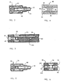
- Figure 2 is a cross-sectional view of the water source block which forms a portion of the preferred embodiment of the manifold assembly, taken along the line 2-2 of Figure 1.
- Figure 3 is a cross-sectional view of the alternating block which forms a portion of the preferred embodiment of the manifold assembly, taken along the line 3-3 of Figure 1.
- Figure 4 is an exploded cross-sectional view of the pressure reducer included in the channel of the alternating block, taken along the line 4-4 of Figure 1.
- Figure 5 is a cross-sectional view of the gas input block which forms a portion of the preferred embodiment of the manifold assembly, taken along the line 5-5 of Figure 1.
- Figure 6 is a partial cross-sectional view of the fill block which forms a portion of the preferred embodiment of the manifold assembly, taken along the line 6-6 of Figure 1.
- Figure 7 is an exploded cross-sectional view of a solenoid diaphragm valve utilized in the preferred embodiment.
- Figure 8 is a partial cross-sectional view of the vessel communication block which forms a portion of the preferred embodiment of the manifold assembly, taken along the line 8-8 of Figure 1.
- Figure 9 a side cross-sectional view of the vessel taken along the line 9-9 of Figure 1, illustrating the drain tube and the level sensors.
- a compact dry vapor delivery apparatus for providing dry vapor to a strip chamber.
- the compact size of the apparatus renders it particularly useful with existing gas panels and equipment with limited space and permits a timed replacement of evaporated liquid to take place while a wafer containing stripped semiconductor chips is being transferred out of the photoresist strip chamber and replaced with another wafer for stripping.
- the delivery apparatus includes a novel manifold assembly 10 for supplying liquid from a liquid supply to an enclosed vessel 12 and settling chamber 14 for generating dry vapor.
- the manifold assembly 10 includes a channel for conveying a liquid from a liquid source to the fill tube of the vessel 12. More specifically, the manifold assembly includes at least two blocks, each block having at least one inlet port, one outlet port, a channel connecting the ports, and one mating surface. The blocks are in mating engagement at their mating surfaces such that the outlet port of one block is aligned with the inlet port of another block.
- This design forms a compact manifold assembly capable of enclosure in a VDS housing. Accordingly, it reduces both the "dead leg" and the expensive assembly of parts found in previous vapor delivery systems.
- the liquid generally, deionized water, used to remove the chlorine from a wafer is supplied by means of Teflon tubing to the manifold assembly 10 through a filter (not shown) to a first block, a liquid source block 20.
- this block has an inlet port 22 with a first connector 24, a first outlet port 26, a second outlet port 28 and a channel 30 connecting its ports.
- the liquid source block also includes a three way valve 32 located in the channel, to direct the flow of liquid from the inlet port either to the first outlet port or to the second outlet port.
- the three way valve is normally open to the second outlet port.
- Each of the valves included in the manifold assembly 10 is controlled by a microprocessor (not shown) and appropriate software.
- Liquid is supplied to the manifold assembly 10 from a liquid source and it enters through the liquid source block's inlet port 22 in the first connector 24 and travels though channel 30 to three way valve 32. Until liquid is needed to replenish the liquid in the vessel 12, the liquid cycles through "the liquid source block loop," namely, from the first connector 24 to the three way valve 32 and then to the second outlet port 28. The liquid is normally returned to the liquid source for reconditioning, or it is transported to a drain. This continuous flow helps to limit bacteria and algae growth in the liquid.
- the liquid source block 20 also includes a second connector 34 and a two way valve 36 located in channel 30 between three way valve 32 and second outlet port 28.
- the volume of the liquid flowing through the source block loop is controlled by trimming or widening the opening in the manually operated two way valve 36.
- solenoid diaphragm valves are used to control the flow of liquid and gas through the manifold assembly 10, except for two way valve 36 which is a manual valve. The detailed structure of the preferred embodiment of the solenoid diaphragm valves is described below with reference to Figure 7.
- the microprocessor switches the liquid source block's three way valve 32 such that the valve is open to the liquid source block's first outlet port 26. As shown in Figures 1 and 3, the liquid then enters a second block, alternating block 38, through the alternating block's first inlet port 40.
- the liquid source block 20 and the alternating block 38 are matingly engaged at a mating surface on the liquid source block (not shown) and a first mating surface 42 ( Figure 3) on the alternating block such that the liquid source block's first outlet port 26 is aligned with the alternating block's first inlet port 40.
- All of the manifold assembly's blocks are held together by a plurality of threaded rods 44 that extend the length of one block and threadingly engage a threaded nut 46 included in another block. This design eliminates the need for connectors between the blocks, thereby decreasing the length of the manifold assembly over conventional water delivery systems.
- the pressure of the liquid from the liquid source can range from atmospheric pressure, if liquid is added to the manifold assembly 10 from a bottle, to about 90 psia (pounds per square inch absolute).
- the preferred operating range of the pressure of the liquid as it exits the manifold assembly and enters the vessel 12 is between 14.7 and 75 psia.
- the pressure reducer assists in controlling the pressure of the liquid entering the vessel within a narrow range by reducing the liquid pressure.
- the pressure reducer includes a channel 54 and at least a first spacer 56 and a second spacer 58 that are sized and shaped to obstruct the channel.
- Each spacer includes an orifice 60 having a diameter that is substantially smaller than the diameter of the pressure reducer's channel.
- spacers having a thickness of between 0.020 inches and 0.040 inches with an orifice having a 0.032 inch diameter have been incorporated in the preferred embodiment.
- the liquid's pressure as it enters the first spacer's orifice is determined by the smaller cross-section of the first orifice 60. However, once this liquid passes through the orifice, it enters the larger cross-section between the first and second spacers, which allows the same amount of liquid to flow at the same rate but at a decreased pressure.
- the pressure reducer 48 includes five spacers with offset orifices. Each orifice causes a substantial pressure drop such that the pressure of the liquid from the liquid supply can be effectively reduced to well below the maximum pressure.
- the vessel 12 can be periodically charged with a gas, preferably nitrogen, to drain the vessel if the liquid is thought to be contaminated.
- gas is supplied through a gas source block 64 having an inlet port 66 in a connector 68.
- the gas source block also includes an outlet port 70, a channel 72 connecting its ports, and a mating surface 74.
- the gas source block also includes a two way valve 76 located in the channel between its inlet port and its outlet port.
- the alternating block 38 includes a second inlet port 78 that is directly connected to a first outlet port 80 by a second channel 81, and an outlet channel 84.
- gas flowing through the alternating block is not valved by the pulse valve 50.
- the alternating block also includes a second mating surface 82 ( Figure 3) that is matingly engaged with the gas source block's mating surface 74 such that the alternating block's second inlet port 78 is aligned with the gas source block's outlet port 70.
- the alternating block 38 is also matingly engaged with a fourth block, a fill block 86.
- this block also includes a first inlet port 88, a first outlet port 90 to supply liquid or gas to the vessel 12, a first channel 92 connecting the ports and a first mating surface 94.
- the fill block's first mating surface is matingly engaged with a third mating surface (not shown) on the alternating block such that the alternating block's first outlet port 80 is aligned with the fill block's first inlet port 88.
- the fill block of the preferred embodiment includes a first two way valve, a final valve 96 in its first channel 92 between its first inlet port 88 and its first outlet port 90.
- the final valve 96 is normally closed to prevent vapor from entering the manifold assembly and only opens to transport liquid for refilling or gas for draining the vessel.
- pressurized liquid enters the manifold assembly 10 from the liquid source and loops through the liquid source block loop until the vessel 12 requires additional liquid.
- the microprocessor opens the fill block's final valve 96 and switches the liquid source block's three way valve 32 to permit liquid to exit out the liquid source block's first outlet port 26.
- the microprocessor pulses the alternating block's pulse valve 50 to permit a predetermined volume of liquid to flow through the pulse valve 50 and the alternating block's outlet channel 84 to the fill block's now open final valve 96 and on to the vessel.
- the microprocessor closes the final valve 96 and the alternating block's pulse valve 50, and the microprocessor switches back the liquid source block's three way valve such that it is open to the liquid source block's second outlet port 28.
- the present invention incorporates a substantially reduced "dead leg" between the liquid source block's three way valve 32 and the fill block's final valve 96.
- Most of the liquid entering the manifold assembly 10 is cycled through the liquid source block loop.
- the only liquid that remains in the manifold assembly 10 after the vessel 12 is refilled is trapped between the liquid source block's three way valve 32 and the final valve 96, in the "dead leg.” Consequently, in the preferred embodiment, the length of the "dead leg" is approximately three and one-half inches.
- previously water vapor delivery systems have included a "dead leg" of about six and one-half feet or more.
- the solenoid diaphragm valves utilized in the preferred embodiment are selected from the SV-2 series or the PV-2 series, both manufactured by Parker Hannifin, located at Partek, 1638 S. Research Loop Road, Suite 100, Arlington, Arizona 85710.
- Figure 7 shows an expanded view of a solenoid diaphragm valve 101, including a cap 103 and a cap port 105. Pressurized air in the cap port forces a piston 107 downward in a housing 109.
- the piston 107 interfaces with an upper diaphragm 111, which in turn presses against an upper poppet 113, a lower poppet 115, a lower diaphragm 117 and a bias spring 119.
- the valve 101 also includes a first outlet port 121, a second outlet port 123 and a common inlet port 125.
- this upward force also biases the upper poppet 113 against the upper diaphragm 111 such that the upper poppet is not in contact with its seat 129 and the second outlet port 123 is normally open.
- a downward force on the piston 107 must exceed the sum of the friction forces between an o-ring 131 and the wall of the housing 109, the friction force between the lower poppet 115 and its seat 127, the upward force of the bias spring 119, and the pressure differential between the inlet port 125 and the first outlet port 121.
- the lower poppet 115 will move away from its seat 127 and fluid will start to flow from the inlet port 125 to the first outlet port 121.
- Additional increases in pressure onto the piston 107 will cause the upper poppet 113 to contact its seat 129 closing the connection between the inlet port 125 and the normally open second outlet port 123. Removing the air pressure on the piston 107 will reverse the chain of event as described.
- the structure of a two way valve utilized in the preferred embodiment eliminates the inlet port 125 and the upper poppet 113.
- the stem of the lower poppet 115 is extended such that it contacts the upper diaphragm 111.
- the first outlet port 121 is used as an inlet port. After sufficient pressure is applied to the piston 107, fluid flows from the normally closed inlet port 121 over the lower poppet seat 127 and exits through the second outlet port 123.
- the preferred embodiment of the present invention includes the final valve 96 because the solenoid diaphragm valves incorporated in the manifold assembly 10 are limited in their ability to seal adequately when a pressure differential greater than about 60 psi exists between a valve's inlet and outlet.
- the final valve 96 and the pulse valve 50 can be omitted if valves capable of sealing against a pressure differential of about 90 psi are utilized for the liquid source block's three way valve 32 and the gas source block's two way valve 76.
- the channel to the vessel 12 from the three way valve 32 and the two way valve 76 is preferably sloped or vertical so that liquid and gas exiting the valves automatically drains into the vessel 12.
- the microprocessor of this alternative embodiment pulses the three way valve 32 to permit a predetermined volume of liquid to flow to the vessel.
- This alternative embodiment can also incorporate a one way check valve (not shown) in the liquid source block's channel 30 between the manual two way valve 36 and the second outlet port 28.
- the check valve assists in limiting backstreaming from the drain through the second outlet port 28.
- This embodiment virtually eliminates the "dead leg" between the liquid source and the vessel 12.
- the channel between the vessel and the three way valve 32 is not heated and can act as a condenser for vapor entering the manifold assembly 10 from the vessel causing droplets to form in the channel.
- Such droplets are susceptible to stagnation and contamination unless the channel is sufficiently sloped to drain readily the droplets back into the vessel.
- liquid and gas are supplied to the vessel through a vessel communication block 100 ( Figures 1, 8 and 9).
- This block includes a first inlet port 102, a first outlet port 104 and a supply channel 106 connecting these ports.
- the vessel communication block also includes a mating surface 108 that is matingly engaged with a second mating surface 110 on the fill block 86 such that the vessel communication block's first inlet port 102 is aligned with the fill block's first outlet port 90.
- the vessel communication block 100 also includes a socket 112 ( Figure 8) for receiving the top of the vessel 12 and a filter 114 through which the supply channel 106 passes. The filter assists in purifying liquid before it enters the vessel 12.
- the manifold assembly 10 includes additional structures for draining the vessel 12. This function is generally performed automatically under microprocessor control when the vapor delivery system has not been used for a few days.
- the vessel includes a drain tube 120 ( Figure 9) with an inlet and an outlet.
- the drain tube extends downwardly from the top of the vessel to a distance of about 0.070 inches above the vessel bottom.
- the drain tube's outlet is aligned with a second inlet port 122 in the vessel communication block 100 ( Figures 8 and 9).
- the vessel communication block further includes a second outlet port 124 and a drain channel 126 for transporting the drained liquid away from the vessel.
- the vessel communication block's second outlet port 124 is aligned with a second inlet port 128 in the fill block 86 ( Figure 1).
- the fill block also includes a second outlet port 130, a second channel 132 and a second two way valve 134 in the second channel between the second inlet port 128 and the second outlet port 130 for transporting drained liquid through the fill block.
- That block includes a third inlet port 138, a second outlet port 140 and a third channel 142 connecting the second ports.
- the alternating block's third channel extends perpendicular to its first channel 52 and its second channel 81.
- the fill block's first mating surface 94 ( Figure 6) is matingly engaged with a third mating surface (not shown) on the alternating block. In the preferred embodiment, this engagement aligns the alternating block's first outlet port 80 with the fill block's first inlet port 88 and aligns the fill block's second outlet port 130 with the alternating block's third inlet port 138.
- the alternating block also includes a connector 144 at the end of the third channel to facilitate engagement with a drain (not shown).
- each block is a parallelpiped with perpendicular walls, such that each block has either six equal square sides and ends, or four equal rectangular sides and two square ends.
- their mating surfaces can be sized such that they are substantially the same size and shape.
- the end of one block may be matingly engaged with the side of another block.
- the mating surfaces have a different width and shape.
- one mating surface may include a knife edge 146, as shown in Figures 1 and 6.
- the dry vapor delivery apparatus of the present invention also incorporates a novel vessel 12 for holding liquid.
- the vessel is surrounded by a heater 150 for heating the liquid to generate a vapor.
- Three tubes extend downwardly through the vessel top into the vessel.
- the first tube shown in Figures 1 and 9; is a fill tube 152 for supplying liquid to the vessel.
- the second tube is a thermo-well tube 154 ( Figure 1) for use with a temperature sensor 156 to determine the temperature of the liquid in the vessel, and the third tube is the drain tube 120 ( Figure 9) for removing liquid from the vessel, as described above.
- the vessel also includes a vapor outlet 158 ( Figure 1) that is connected to a strip chamber (not shown) by a passage 160 in the vessel communication block 100.
- the vessel 12 is supported by a base support 162 that is generally cup-shaped.
- the bottom surface of the vessel may be rounded and, therefore, preferably rests on an elastomer pad 164 in the inside bottom surface of the base support.
- the base support is connected to the vessel communication block 100 by four springs and lag screws (not shown) such that the vessel is spring-loaded against the vessel communication block 100 to seal the top of the vessel in the vessel communication block's socket 112.
- o-rings may be included between the drain tube 120, the fill tube 152, the vapor outlet 158, and the socket.
- liquid is supplied to the vessel 12 through the fill tube 152.
- the vapor is dried by transporting the vapor through a settling chamber that is located within the vessel and above its liquid level.
- the wet vapor in the vessel is pressurized by the heating process at subatmospheric pressure, and it enters the settling chamber at a relatively high speed as it passes through a narrow or small opening, a vapor inlet 178.
- the speed of the vapor decreases once the vapor enters the wider settling chamber, thereby allowing liquid drops to settle on the preferably sloped bottom of the settling chamber to form larger drops, and to exit out the vapor inlet and back into the liquid in the vessel.
- the liquid fill tube 152 extends downwardly through the vessel's top, through the settling chamber, and preferably terminates at a depth of about 0.5" above the desired liquid surface. This termination point minimizes splashing during refills which can cause the liquid levels to be incorrectly measured. However, the termination point can be at any point within the vessel 12.
- the other end of the fill tube is connected to the fill block's first outlet port 90 through the supply channel 106 in the vessel communication block 100 ( Figure 1).
- the fill tube 152 has a sufficiently large diameter to permit complete replenishment of evaporated liquid while a semiconductor chip is being transferred out of the strip chamber to minimize the effect of refills on the thruput of the etching system.
- the fill tube is also used to add gas to the vessel 12 to pressurize it above atmospheric pressure and to force liquid down in the vessel and up the drain tube 120 for a drain cycle. Another use of the fill tube is to insert boiling chips or balls into the vessel 12.
- the pressurized vessel 12 is filled with cold liquid.
- the heater 150 then heats the liquid to the vapor system setpoint (50-65° C).
- the vessel is heated by a flexible foil heater having higher wattage density where the vessel is contacted by liquid and near the top of the vessel to minimize condensation in the settling chambers.
- the foil heater is provided with a built-in temperature sensor (not shown) embedded in the upper edge of the foil to measure the temperature of the heater and to cut off power to the heater if the heater's temperature exceeds a predetermined level.
- the foil heater 150 also preferably has multiple viewing ports 166 which allow the use of optical sensors 168 ( Figure 9), located outside of the vessel 12, for sensing the level of the liquid in the vessel through the viewing ports.
- optical sensors 168 Figure 9
- two liquid meniscus sensors comprising two emitters and two receivers, as illustrated by the dashed lines between the sensors.
- the lower left receiver and the upper right emitter sense the level of the liquid when it reaches a normal level
- the upper left emitter and the lower right receiver sense the level of the liquid in the vessel when it exceeds an overflow level.
- the fill tube 152 and the drain tube 120 are not in the optical path of the level sensors.
- Heating the vessel's liquid at subatmospheric pressure tends to cause a significantly violent boiling action, so-called nucleate boiling, where relatively large diameter vapor bubbles up to 1" diameter can be generated in the vessel 12 due to the absence of surface roughness in the quartz vessel.
- This violent boiling action also tends to diminish somewhat after degassing of the liquid is completed so that only vapor is generated.
- the addition of boiling chips 170, preferably polytetrafluoroethylene balls, to the bottom of the vessel tends to reduce this violent boiling action, releasing instead a continuous flow of smaller bubbles at higher flow rates. A single layer of chips is sufficient to obtain the desired effect.
- two settling chambers 172 and 174 are located within the vessel 12, one above the other, with the first settling chamber 172 located below the second settling chamber 174 and above the desired liquid level of the vessel.
- the bottom wall of each settling chamber slopes downwardly toward the vapor inlet/drain 178, the narrow opening described above, preferably located at the lowest point to ensure proper drainage.
- a sloped dividing wall 176 separates the first settling chamber 172 from the second settling chamber 174, thereby simultaneously acting as a top wall for the first settling chamber and a bottom wall for the second settling chamber.
- Vapor enters the first settling chamber through the vapor inlet 178, the narrow opening or slit located in the lower end of the first settling chamber's bottom wall 180.
- the vapor inlet's cross-section is substantially smaller than the vessel's cross-section. More particularly, the preferred ratio of the vessel cross-section to the vapor inlet's cross-section is approximately 50 to 1. Additionally, the preferred ratio of the first settling chamber's cross-section at the vapor inlet to the vapor inlet's cross-section is approximately 16 to 1.
- the vapor speed is relatively high as it travels through the vapor inlet because the vapor inlet's cross-section is 50 times smaller than the vessel's cross-section. Then, the vapor's speed decreases when it passes into the first settling chamber, because the vapor inlet's cross-section is only 16 times smaller than the first settling chamber's cross-section.
- the vapor inlet can be any size that causes the vapor to lose speed after it enters the first settling chamber.
- the small size of the vapor inlet also serves to limit the amount of liquid entering the first settling chamber and prevents the boiling chips 170 from entering or plugging the vapor inlet during moving of the system.
- the partially dry vapor exits the first settling chamber through a vapor orifice 182, preferably located near the lower end of the sloped dividing wall 176 between the settling chambers.
- the vapor orifice 182 acts as a vapor outlet for the first settling chamber and a second vapor inlet and drain for the second settling chamber.
- thermo-well tube 154 extends from the top of the vessel 12 through the first and second settling chambers 172 and 174 and into the vessel 12 such that it terminates preferably one inch below the desired liquid surface.
- the thermo-well tube is closed at its bottom end and a temperature sensor, in the form of the temperature sensor 156 referred to above, is positioned inside. Good heat transfer can be insured by using a heatsink compound between the temperature sensor and the thermo-well tube.
- the vessel 12 is generally cylindrical with a two inch diameter, a dome-shaped bottom and a flat top.
- the diameter of the vessel is sized to generate vapor at a selected rate, as required by the strip chamber. It has been determined that a diameter of two inches is capable of generating vapor at a rate of approximately one liter of vapor per minute.
- the vessel is preferably made from quartz for its excellent resistance to chemical attack by liquid and to permit a visual inspection of its liquid level. Overall, the described apparatus has been demonstrated as capable of delivering vapor at a rate of up to 1000 sccm (standard cubic centimeter per minute) without flow spikes registered by a mass flow controller.
- a liquid is supplied to the manifold assembly 10 and to the vessel 12 through the fill tube 152 which is connected to the manifold assembly's channel.
- the liquid is heated to a sufficient temperature to generate a vapor.
- the vapor is then transported to a settling chamber located within the vessel through a vapor inlet having a cross-section that is smaller than the vessel's cross-section. The speed of the vapor is decreased, thereby allowing liquid drops to settle out of the vapor.
- the liquid drops are returned to the bottom of the vessel, and the relatively dry vapor is transported out of the settling chamber.
- the vapor is transported out of the settling chamber, and into a second settling chamber where additional liquid drops can settle out of the vapor. These liquid drops are also returned to the bottom of the vessel, and the dry vapor is transported out of the second settling chamber, preferably to the strip chamber.
- the present invention provides an improved dry vapor delivery apparatus with minimal liquid stagnation from liquid supply to vapor generator.
- the preferred embodiment significantly decreases the "dead leg" found in previous vapor delivery apparatuses and permits delivery of vapor at a desirable rate without apparent mass flow controller pressure spikes.
- the compact size of the apparatus allows it to be installed in existing equipment with minimum modifications, if any.
- the apparatus and method of the present invention may also be used to generate vapor from other liquids. It works particularly well with base liquids, that is, liquids composed of molecules having an hydroxyl ion, OH, such as acetic acid and hydrogen peroxide. Water is another base liquid. Additionally, gases other than nitrogen may be used to charge the vessel to drain the liquid.
- base liquids that is, liquids composed of molecules having an hydroxyl ion, OH, such as acetic acid and hydrogen peroxide. Water is another base liquid. Additionally, gases other than nitrogen may be used to charge the vessel to drain the liquid.
- the blocks in the preferred embodiment of the manifold assembly 10 are essentially arranged in a two dimensional formation, they may also be arranged in three dimensions without departing from the scope of the present invention. Of course, an alternative arrangement of the blocks may require changes in the channels and block interfaces from those described in the preferred embodiment. Accordingly, the invention is limited only by the following claims.
Landscapes
- Engineering & Computer Science (AREA)
- Mechanical Engineering (AREA)
- Chemical Kinetics & Catalysis (AREA)
- Sustainable Development (AREA)
- Sustainable Energy (AREA)
- Physics & Mathematics (AREA)
- Life Sciences & Earth Sciences (AREA)
- Thermal Sciences (AREA)
- General Engineering & Computer Science (AREA)
- Chemical & Material Sciences (AREA)
- Cleaning Or Drying Semiconductors (AREA)
- Drying Of Solid Materials (AREA)
- Treatments For Attaching Organic Compounds To Fibrous Goods (AREA)
- Vaporization, Distillation, Condensation, Sublimation, And Cold Traps (AREA)
- Sampling And Sample Adjustment (AREA)
- Physical Or Chemical Processes And Apparatus (AREA)
- Extraction Or Liquid Replacement (AREA)
Applications Claiming Priority (3)
| Application Number | Priority Date | Filing Date | Title |
|---|---|---|---|
| US08/227,973 US5537508A (en) | 1993-03-22 | 1994-04-15 | Method and dry vapor generator channel assembly for conveying a liquid from a liquid source to a liquid vaporizer with minimal liquid stagnation |
| US227973 | 1994-04-15 | ||
| EP95105759A EP0677703B1 (de) | 1994-04-15 | 1995-04-18 | Methode und Vorrichtung zur Erzeugung von trockenem Dampf |
Related Parent Applications (1)
| Application Number | Title | Priority Date | Filing Date |
|---|---|---|---|
| EP95105759A Division EP0677703B1 (de) | 1994-04-15 | 1995-04-18 | Methode und Vorrichtung zur Erzeugung von trockenem Dampf |
Publications (3)
| Publication Number | Publication Date |
|---|---|
| EP0874193A2 true EP0874193A2 (de) | 1998-10-28 |
| EP0874193A3 EP0874193A3 (de) | 1998-12-16 |
| EP0874193B1 EP0874193B1 (de) | 2001-01-10 |
Family
ID=22855225
Family Applications (2)
| Application Number | Title | Priority Date | Filing Date |
|---|---|---|---|
| EP95105759A Expired - Lifetime EP0677703B1 (de) | 1994-04-15 | 1995-04-18 | Methode und Vorrichtung zur Erzeugung von trockenem Dampf |
| EP98113092A Expired - Lifetime EP0874193B1 (de) | 1994-04-15 | 1995-04-18 | Methode und Vorrichtung zur Erzeugung von trockenem Dampf |
Family Applications Before (1)
| Application Number | Title | Priority Date | Filing Date |
|---|---|---|---|
| EP95105759A Expired - Lifetime EP0677703B1 (de) | 1994-04-15 | 1995-04-18 | Methode und Vorrichtung zur Erzeugung von trockenem Dampf |
Country Status (6)
| Country | Link |
|---|---|
| US (1) | US5537508A (de) |
| EP (2) | EP0677703B1 (de) |
| JP (1) | JPH0882402A (de) |
| KR (1) | KR100362770B1 (de) |
| AT (2) | ATE198648T1 (de) |
| DE (2) | DE69519880T2 (de) |
Cited By (2)
| Publication number | Priority date | Publication date | Assignee | Title |
|---|---|---|---|---|
| EP1323478A3 (de) * | 2001-12-25 | 2004-10-27 | Maruyasu Industries Co., Ltd. | Dampf/Flüssigkeitsabscheider |
| EP1553342A1 (de) * | 2003-12-31 | 2005-07-13 | Electrodomesticos Taurus S.L. | Druckaufgeladener Dampferzeuger |
Families Citing this family (14)
| Publication number | Priority date | Publication date | Assignee | Title |
|---|---|---|---|---|
| US5949958A (en) * | 1995-06-07 | 1999-09-07 | Steris Corporation | Integral flash steam generator |
| ATE522926T1 (de) * | 1997-02-14 | 2011-09-15 | Imec | Verfahren zur entfernung organischer kontamination von einer halbleiteroberfläche |
| US6350322B1 (en) * | 1997-03-21 | 2002-02-26 | Micron Technology, Inc. | Method of reducing water spotting and oxide growth on a semiconductor structure |
| DE19810833B4 (de) * | 1998-03-12 | 2004-08-12 | Herz, Helmut, Dr.-Ing. | Einrichtung zur thermischen Behandlung von Flüssigkeiten |
| FR2793703B1 (fr) * | 1999-05-19 | 2001-06-29 | Inst Francais Du Petrole | Procede de fabrication de compositions utilisables comme agents de surface emulsifiants et dispersants, les compositions obtenues et leurs utilisations |
| US7003215B2 (en) * | 2002-01-21 | 2006-02-21 | Air Products And Chemicals, Inc. | Vapor flow controller |
| US20030234929A1 (en) * | 2002-06-24 | 2003-12-25 | Applied Materials, Inc. | Method and system to reduce/detect a presence of gas in a flow of a cleaning fluid |
| US7776228B2 (en) * | 2006-04-11 | 2010-08-17 | Ebara Corporation | Catalyst-aided chemical processing method |
| EP1890097A1 (de) * | 2006-08-07 | 2008-02-20 | Electrolux Home Products Corporation N.V. | Kühlschrank mit Trinkflüssigkeitabgabeeinrichtung, und System zur Versorgung von Informationen bezüglich des Zustands der Flüssigkeit in der Abgabeeinrichtung |
| US8297223B2 (en) * | 2007-10-02 | 2012-10-30 | Msp Corporation | Method and apparatus for particle filtration and enhancing tool performance in film deposition |
| US8734661B2 (en) | 2007-10-15 | 2014-05-27 | Ebara Corporation | Flattening method and flattening apparatus |
| US9259533B2 (en) * | 2008-03-31 | 2016-02-16 | Covidien Lp | Safety needle with spring biased retraction mechanism |
| US9451792B1 (en) * | 2014-09-05 | 2016-09-27 | Atmos Nation, LLC | Systems and methods for vaporizing assembly |
| CN105714271B (zh) * | 2014-12-22 | 2020-07-31 | 株式会社堀场Stec | 汽化系统 |
Family Cites Families (31)
| Publication number | Priority date | Publication date | Assignee | Title |
|---|---|---|---|---|
| US1355935A (en) * | 1920-10-19 | benjamin | ||
| US570790A (en) * | 1896-11-03 | Separator | ||
| US644862A (en) * | 1899-05-06 | 1900-03-06 | David S Jacobus | Boiler. |
| DE359303C (de) * | 1921-03-27 | 1922-09-21 | Bbc Brown Boveri & Cie | Einrichtung zum Betrieb von Elektrodendampfkesseln |
| US2494654A (en) * | 1948-09-07 | 1950-01-17 | Super Mold Corp | Boiler |
| GB681356A (en) * | 1949-03-23 | 1952-10-22 | Frank George Jefferies | Improvements in or relating to electrically operated steam generating apparatus and the like |
| DE1117228B (de) * | 1959-02-21 | 1961-11-16 | Peter Franken | Als Handgeraet ausgebildeter, elektrisch beheizter Dampfapparat, vorzugsweise fuer die Koerper- und Gesundheitspflege |
| FR1237897A (fr) * | 1959-06-25 | 1960-08-05 | C E V I N | Générateur portatif de vapeur |
| GB890306A (en) * | 1959-08-13 | 1962-02-28 | Parnall & Sons Ltd | An improved water evaporating unit for dispersing de-frost water from a refrigerator |
| US3267678A (en) * | 1964-05-06 | 1966-08-23 | Camp Nat | Vapor-generating device |
| US3339531A (en) * | 1965-06-29 | 1967-09-05 | William J Fitzgerald | Flash-type steam generators |
| US3637979A (en) * | 1969-01-16 | 1972-01-25 | Sprinkler Corp Of America | Educational apparatus |
| US3654780A (en) * | 1971-04-21 | 1972-04-11 | Dart Ind Inc | Clothes steamer device |
| US4091056A (en) * | 1972-06-28 | 1978-05-23 | Veikko Hamalainen | Method of vaporizing liquids |
| US4098853A (en) * | 1974-03-25 | 1978-07-04 | Chemetron Corporation | Humidifier and automatic control system therefor |
| US4276243A (en) * | 1978-12-08 | 1981-06-30 | Western Electric Company, Inc. | Vapor delivery control system and method |
| SU832247A1 (ru) * | 1979-04-04 | 1981-05-23 | Одесский Филиал Научно-Производственногообъединения "Агроприбор" | Электродный котел |
| US4281636A (en) * | 1979-06-07 | 1981-08-04 | Vegh Elmer S | Steam processor |
| US4356834A (en) * | 1979-11-02 | 1982-11-02 | Lemay Dan B | Vapor feed regulator |
| US4436674A (en) * | 1981-07-30 | 1984-03-13 | J.C. Schumacher Co. | Vapor mass flow control system |
| FR2512473A1 (fr) * | 1981-09-09 | 1983-03-11 | Maksa Christian | Dispositif de repassage a vapeur sous pression |
| US4878458A (en) * | 1987-08-31 | 1989-11-07 | Nelson Clinton D | Method and apparatus for generating pressurized fluid |
| US4977094A (en) * | 1987-12-28 | 1990-12-11 | Ionics, Incorporated | Process for monitoring the quality of water |
| FR2625794B1 (fr) * | 1988-01-08 | 1990-05-04 | Bourgeois Ste Coop Production | Generateur de vapeur d'eau pour appareil de cuisson |
| JPH01249666A (ja) * | 1988-03-31 | 1989-10-04 | Nippon Steel Corp | 溶射によるセラミックの接合方法 |
| JPH02267985A (ja) * | 1989-04-07 | 1990-11-01 | Matsushita Electric Ind Co Ltd | Co↓2ガスレーザ制御装置 |
| US5063609A (en) * | 1989-10-11 | 1991-11-05 | Applied Materials, Inc. | Steam generator |
| FR2653208B3 (fr) * | 1989-10-13 | 1991-12-06 | Bonnet Sa | Chaudiere pour l'alimentation en vapeur d'un four de cuisson d'aliments. |
| JPH05164878A (ja) * | 1991-12-17 | 1993-06-29 | Hitachi Ltd | 気水分離器・蒸気乾燥器一体構造 |
| JPH0629277A (ja) * | 1992-07-08 | 1994-02-04 | Hitachi Ltd | ベーパ乾燥装置 |
| US5399200A (en) * | 1994-03-10 | 1995-03-21 | Stauffer; Craig M. | Module in an integrated delivery system for chemical vapors from liquid sources |
-
1994
- 1994-04-15 US US08/227,973 patent/US5537508A/en not_active Expired - Fee Related
-
1995
- 1995-04-14 KR KR1019950008754A patent/KR100362770B1/ko not_active Expired - Fee Related
- 1995-04-17 JP JP7090861A patent/JPH0882402A/ja not_active Withdrawn
- 1995-04-18 EP EP95105759A patent/EP0677703B1/de not_active Expired - Lifetime
- 1995-04-18 DE DE69519880T patent/DE69519880T2/de not_active Expired - Fee Related
- 1995-04-18 AT AT98113092T patent/ATE198648T1/de not_active IP Right Cessation
- 1995-04-18 DE DE69507365T patent/DE69507365D1/de not_active Expired - Lifetime
- 1995-04-18 AT AT95105759T patent/ATE176038T1/de not_active IP Right Cessation
- 1995-04-18 EP EP98113092A patent/EP0874193B1/de not_active Expired - Lifetime
Non-Patent Citations (1)
| Title |
|---|
| None |
Cited By (3)
| Publication number | Priority date | Publication date | Assignee | Title |
|---|---|---|---|---|
| EP1323478A3 (de) * | 2001-12-25 | 2004-10-27 | Maruyasu Industries Co., Ltd. | Dampf/Flüssigkeitsabscheider |
| US6977004B2 (en) | 2001-12-25 | 2005-12-20 | Maruyasu Industries Co. Ltd. | Vapor-liquid separator |
| EP1553342A1 (de) * | 2003-12-31 | 2005-07-13 | Electrodomesticos Taurus S.L. | Druckaufgeladener Dampferzeuger |
Also Published As
| Publication number | Publication date |
|---|---|
| DE69507365D1 (de) | 1999-03-04 |
| DE69519880D1 (de) | 2001-02-15 |
| ATE176038T1 (de) | 1999-02-15 |
| EP0874193B1 (de) | 2001-01-10 |
| EP0874193A3 (de) | 1998-12-16 |
| KR100362770B1 (ko) | 2003-02-11 |
| EP0677703B1 (de) | 1999-01-20 |
| DE69519880T2 (de) | 2001-08-02 |
| EP0677703A1 (de) | 1995-10-18 |
| ATE198648T1 (de) | 2001-01-15 |
| JPH0882402A (ja) | 1996-03-26 |
| US5537508A (en) | 1996-07-16 |
| KR950034569A (ko) | 1995-12-28 |
Similar Documents
| Publication | Publication Date | Title |
|---|---|---|
| EP0874193B1 (de) | Methode und Vorrichtung zur Erzeugung von trockenem Dampf | |
| US5425803A (en) | Device for removing dissolved gas from a liquid | |
| KR100390545B1 (ko) | 기판세정건조장치,기판세정방법및기판세정장치 | |
| TWI428975B (zh) | 用於回收在處理環境中之處理流體的系統和方法 | |
| KR100985087B1 (ko) | 오존수 유량 및 농도 조절 장치 및 방법 | |
| CN102986008B (zh) | 用于去离子水的碳酸化的装置、系统及方法 | |
| US20100065414A1 (en) | Water heating and distillation arrangement | |
| US5293893A (en) | Empty drum detecting apparatus | |
| KR980012044A (ko) | 기판건조장치 및 기판건조방법 | |
| US6955758B2 (en) | Ozone treating apparatus | |
| US6017827A (en) | System and method for mixing a gas into a solvent used in semiconductor processing | |
| KR19990029830A (ko) | 사용장소까지초고순도가스를이송하기위한시스템및방법 | |
| TW200831812A (en) | Low vapor pressure high purity gas delivery system | |
| US5613364A (en) | Compact replaceable temperature control module | |
| US6253775B1 (en) | Cleaning apparatus | |
| KR20030093118A (ko) | 불소가스 발생장치 | |
| US8118939B2 (en) | Temperature control unit for bubblers | |
| CN1487868A (zh) | 发送液体化学合成物的压力容器系统和方法 | |
| JP2000271549A (ja) | ガス溶解水供給装置 | |
| JP5412135B2 (ja) | オゾン水供給装置 | |
| EP1102947A1 (de) | Spendervorrichtung für chemikalien mit entlüftungssystem unter verwendung verschiedener entlüftungstechniken | |
| JPH1177021A (ja) | 水素含有超純水の供給装置 | |
| US5318706A (en) | Method of supplying dilute hydrofluoric acid and apparatus for use in this method for supplying the acid | |
| CN1242248A (zh) | 连续的气体饱和系统及方法 | |
| KR100466148B1 (ko) | 기판건조장치및기판건조방법 |
Legal Events
| Date | Code | Title | Description |
|---|---|---|---|
| PUAI | Public reference made under article 153(3) epc to a published international application that has entered the european phase |
Free format text: ORIGINAL CODE: 0009012 |
|
| 17P | Request for examination filed |
Effective date: 19980714 |
|
| AC | Divisional application: reference to earlier application |
Ref document number: 677703 Country of ref document: EP |
|
| AK | Designated contracting states |
Kind code of ref document: A2 Designated state(s): AT BE CH DE ES FR GB GR IE IT LI NL SE |
|
| PUAL | Search report despatched |
Free format text: ORIGINAL CODE: 0009013 |
|
| AK | Designated contracting states |
Kind code of ref document: A3 Designated state(s): AT BE CH DE ES FR GB GR IE IT LI NL SE |
|
| GRAG | Despatch of communication of intention to grant |
Free format text: ORIGINAL CODE: EPIDOS AGRA |
|
| 17Q | First examination report despatched |
Effective date: 20000301 |
|
| GRAG | Despatch of communication of intention to grant |
Free format text: ORIGINAL CODE: EPIDOS AGRA |
|
| GRAG | Despatch of communication of intention to grant |
Free format text: ORIGINAL CODE: EPIDOS AGRA |
|
| GRAH | Despatch of communication of intention to grant a patent |
Free format text: ORIGINAL CODE: EPIDOS IGRA |
|
| GRAH | Despatch of communication of intention to grant a patent |
Free format text: ORIGINAL CODE: EPIDOS IGRA |
|
| GRAA | (expected) grant |
Free format text: ORIGINAL CODE: 0009210 |
|
| AC | Divisional application: reference to earlier application |
Ref document number: 677703 Country of ref document: EP |
|
| AK | Designated contracting states |
Kind code of ref document: B1 Designated state(s): AT BE CH DE ES FR GB GR IE IT LI NL SE |
|
| PG25 | Lapsed in a contracting state [announced via postgrant information from national office to epo] |
Ref country code: SE Free format text: THE PATENT HAS BEEN ANNULLED BY A DECISION OF A NATIONAL AUTHORITY Effective date: 20010110 Ref country code: NL Free format text: LAPSE BECAUSE OF FAILURE TO SUBMIT A TRANSLATION OF THE DESCRIPTION OR TO PAY THE FEE WITHIN THE PRESCRIBED TIME-LIMIT Effective date: 20010110 Ref country code: LI Free format text: LAPSE BECAUSE OF FAILURE TO SUBMIT A TRANSLATION OF THE DESCRIPTION OR TO PAY THE FEE WITHIN THE PRESCRIBED TIME-LIMIT Effective date: 20010110 Ref country code: IT Free format text: LAPSE BECAUSE OF FAILURE TO SUBMIT A TRANSLATION OF THE DESCRIPTION OR TO PAY THE FEE WITHIN THE PRESCRIBED TIME-LIMIT;WARNING: LAPSES OF ITALIAN PATENTS WITH EFFECTIVE DATE BEFORE 2007 MAY HAVE OCCURRED AT ANY TIME BEFORE 2007. THE CORRECT EFFECTIVE DATE MAY BE DIFFERENT FROM THE ONE RECORDED. Effective date: 20010110 Ref country code: ES Free format text: THE PATENT HAS BEEN ANNULLED BY A DECISION OF A NATIONAL AUTHORITY Effective date: 20010110 Ref country code: CH Free format text: LAPSE BECAUSE OF FAILURE TO SUBMIT A TRANSLATION OF THE DESCRIPTION OR TO PAY THE FEE WITHIN THE PRESCRIBED TIME-LIMIT Effective date: 20010110 Ref country code: BE Free format text: LAPSE BECAUSE OF FAILURE TO SUBMIT A TRANSLATION OF THE DESCRIPTION OR TO PAY THE FEE WITHIN THE PRESCRIBED TIME-LIMIT Effective date: 20010110 Ref country code: AT Free format text: LAPSE BECAUSE OF FAILURE TO SUBMIT A TRANSLATION OF THE DESCRIPTION OR TO PAY THE FEE WITHIN THE PRESCRIBED TIME-LIMIT Effective date: 20010110 |
|
| REF | Corresponds to: |
Ref document number: 198648 Country of ref document: AT Date of ref document: 20010115 Kind code of ref document: T |
|
| REG | Reference to a national code |
Ref country code: CH Ref legal event code: EP |
|
| REG | Reference to a national code |
Ref country code: IE Ref legal event code: FG4D |
|
| REF | Corresponds to: |
Ref document number: 69519880 Country of ref document: DE Date of ref document: 20010215 |
|
| ET | Fr: translation filed | ||
| PG25 | Lapsed in a contracting state [announced via postgrant information from national office to epo] |
Ref country code: GR Free format text: LAPSE BECAUSE OF FAILURE TO SUBMIT A TRANSLATION OF THE DESCRIPTION OR TO PAY THE FEE WITHIN THE PRESCRIBED TIME-LIMIT Effective date: 20010413 |
|
| PG25 | Lapsed in a contracting state [announced via postgrant information from national office to epo] |
Ref country code: IE Free format text: LAPSE BECAUSE OF NON-PAYMENT OF DUE FEES Effective date: 20010418 |
|
| PGFP | Annual fee paid to national office [announced via postgrant information from national office to epo] |
Ref country code: DE Payment date: 20010427 Year of fee payment: 7 |
|
| PGFP | Annual fee paid to national office [announced via postgrant information from national office to epo] |
Ref country code: GB Payment date: 20010502 Year of fee payment: 7 |
|
| PGFP | Annual fee paid to national office [announced via postgrant information from national office to epo] |
Ref country code: FR Payment date: 20010518 Year of fee payment: 7 |
|
| NLV1 | Nl: lapsed or annulled due to failure to fulfill the requirements of art. 29p and 29m of the patents act | ||
| REG | Reference to a national code |
Ref country code: CH Ref legal event code: PL |
|
| PLBE | No opposition filed within time limit |
Free format text: ORIGINAL CODE: 0009261 |
|
| STAA | Information on the status of an ep patent application or granted ep patent |
Free format text: STATUS: NO OPPOSITION FILED WITHIN TIME LIMIT |
|
| REG | Reference to a national code |
Ref country code: GB Ref legal event code: IF02 |
|
| 26N | No opposition filed | ||
| REG | Reference to a national code |
Ref country code: IE Ref legal event code: MM4A |
|
| PG25 | Lapsed in a contracting state [announced via postgrant information from national office to epo] |
Ref country code: GB Free format text: LAPSE BECAUSE OF NON-PAYMENT OF DUE FEES Effective date: 20020418 |
|
| PG25 | Lapsed in a contracting state [announced via postgrant information from national office to epo] |
Ref country code: DE Free format text: LAPSE BECAUSE OF NON-PAYMENT OF DUE FEES Effective date: 20021101 |
|
| GBPC | Gb: european patent ceased through non-payment of renewal fee |
Effective date: 20020418 |
|
| PG25 | Lapsed in a contracting state [announced via postgrant information from national office to epo] |
Ref country code: FR Free format text: LAPSE BECAUSE OF NON-PAYMENT OF DUE FEES Effective date: 20021231 |
|
| REG | Reference to a national code |
Ref country code: FR Ref legal event code: ST |