EP0877322A2 - Zustandinformationverwaltungsverfahren und Übertragungssystem - Google Patents
Zustandinformationverwaltungsverfahren und Übertragungssystem Download PDFInfo
- Publication number
- EP0877322A2 EP0877322A2 EP98108339A EP98108339A EP0877322A2 EP 0877322 A2 EP0877322 A2 EP 0877322A2 EP 98108339 A EP98108339 A EP 98108339A EP 98108339 A EP98108339 A EP 98108339A EP 0877322 A2 EP0877322 A2 EP 0877322A2
- Authority
- EP
- European Patent Office
- Prior art keywords
- state information
- recovery command
- report
- transmitting
- communication
- Prior art date
- Legal status (The legal status is an assumption and is not a legal conclusion. Google has not performed a legal analysis and makes no representation as to the accuracy of the status listed.)
- Granted
Links
Images

Classifications
-
- H—ELECTRICITY
- H04—ELECTRIC COMMUNICATION TECHNIQUE
- H04L—TRANSMISSION OF DIGITAL INFORMATION, e.g. TELEGRAPHIC COMMUNICATION
- H04L12/00—Data switching networks
- H04L12/28—Data switching networks characterised by path configuration, e.g. LAN [Local Area Networks] or WAN [Wide Area Networks]
- H04L12/2803—Home automation networks
- H04L12/2823—Reporting information sensed by appliance or service execution status of appliance services in a home automation network
- H04L12/2827—Reporting to a device within the home network; wherein the reception of the information reported automatically triggers the execution of a home appliance functionality
-
- H—ELECTRICITY
- H04—ELECTRIC COMMUNICATION TECHNIQUE
- H04L—TRANSMISSION OF DIGITAL INFORMATION, e.g. TELEGRAPHIC COMMUNICATION
- H04L12/00—Data switching networks
- H04L12/28—Data switching networks characterised by path configuration, e.g. LAN [Local Area Networks] or WAN [Wide Area Networks]
- H04L12/2803—Home automation networks
- H04L12/2805—Home Audio Video Interoperability [HAVI] networks
-
- H—ELECTRICITY
- H04—ELECTRIC COMMUNICATION TECHNIQUE
- H04L—TRANSMISSION OF DIGITAL INFORMATION, e.g. TELEGRAPHIC COMMUNICATION
- H04L41/00—Arrangements for maintenance, administration or management of data switching networks, e.g. of packet switching networks
- H04L41/04—Network management architectures or arrangements
- H04L41/044—Network management architectures or arrangements comprising hierarchical management structures
-
- H—ELECTRICITY
- H04—ELECTRIC COMMUNICATION TECHNIQUE
- H04L—TRANSMISSION OF DIGITAL INFORMATION, e.g. TELEGRAPHIC COMMUNICATION
- H04L41/00—Arrangements for maintenance, administration or management of data switching networks, e.g. of packet switching networks
- H04L41/08—Configuration management of networks or network elements
- H04L41/0803—Configuration setting
- H04L41/0813—Configuration setting characterised by the conditions triggering a change of settings
- H04L41/0816—Configuration setting characterised by the conditions triggering a change of settings the condition being an adaptation, e.g. in response to network events
-
- H—ELECTRICITY
- H04—ELECTRIC COMMUNICATION TECHNIQUE
- H04L—TRANSMISSION OF DIGITAL INFORMATION, e.g. TELEGRAPHIC COMMUNICATION
- H04L12/00—Data switching networks
- H04L12/28—Data switching networks characterised by path configuration, e.g. LAN [Local Area Networks] or WAN [Wide Area Networks]
- H04L12/2803—Home automation networks
- H04L2012/284—Home automation networks characterised by the type of medium used
- H04L2012/2841—Wireless
Definitions
- the present invention relates to a state information managing method which is able to manage easily state information of respective communication units and also reduce a communication traffic volume required for management of state information in a communication system wherein a plurality of communication units for exchanging data communication mutually are connected to a bus, and a communication system.
- respective communication units can exchange data communication mutually.
- state information indicating the internal states have been managed by the communication units respectively.
- the state information management method there has been such a method that, when the data management portion issues a state request to respective communication units, such respective communication units transmits a state response to the data management portion in response to the state request from the data management portion.
- this method since the state request and the state response must be issued from respective communication units, an extensive communication traffic volume has been needed.
- the first method to reduce the communication traffic volume of the state request.
- the communication units which receive such state request have transmitted automatically state reports to the state information collecting destination subsequently every time when their states are changed. According to the first method, the communication traffic volume of the state request can be reduced.
- the system set forth in Patent Application Publication (KOKAI) Sho 62-194759 is the communication system in which a plurality of nodes are connected like a loop and signals are transmitted in one way.
- a series of call setting procedures which are constructed by transmitting additional information necessary for call setting request for the transmitter side node issued from the transmitter side node and call setting allowance or call setting refuse and call setting are transmitted via packet transmission.
- the present invention has been made in light of the above circumstances, and it is an object of the present invention to provide a state information managing method which is able to manage easily state information of respective communication units and also reduce a communication traffic volume required for management of the state information, and a communication system.
- a state information managing method wherein collecting communication unit in a plurality of communication units are able to collect state information indicating respective states from one or more report communication units except the collecting communication unit to manage their state information in a communication system in which the plurality of communication units are connected to a bus to exchange mutual communication, comprising: a state monitoring step of monitoring the state information of own communication unit in respective report communication units, and rewriting the state information stored in a memory portion into new state information after change if the state information in own communication unit has been changed; a transmitting step of transmitting a recovery command for recovering the state information from the collecting communication unit; a transmitting/receiving step of adding the state information stored in the memory portion and own address to the recovery command and then transmitting the recovery command when respective report communication units receive the recovery command; and a receiving step of receiving the recovery command to which changed state information and their own addresses of respective report communication units are added collectively, by the collecting communication unit.
- the state information in own communication unit is monitored whether or not the state information in own communication unit has been changed, then the state information stored in a memory portion is rewritten if the state information has been changed, then the changed state information and own address are added to the recovery command when respective report communication units receive the recovery command, and then the recovery command is transmitted.
- the collecting communication unit receives the recovery command to which the changed state information and their own addresses of respective report communication units are added collectively.
- the collecting communication unit can acquire the state information of respective report communication units by receiving the recovery command only once, the communication traffic volume can be reduced and also collision of the state information sent out from respective report communication units can be avoided.
- the state monitoring step rewrites the state information stored in the memory portion into new state information after change if the state information of own communication unit is changed, and then sets a report flag added to the memory portion
- the transmitting/receiving step adds the state information stored in the memory portion and their own addresses to the recovery command and then transmits the recovery command if the report flag has been set when respective report communication units receive the recovery command, and then resets the report flag.
- the transmitting/receiving step transmits the recovery command received as it is unless the report flag has been set when respective report communication units receive the recovery command.
- the report flag is set when the state information has been changed and the report flag is reset when the state information and the their own addresses after the change are added to the recovery command, so that it can be grasped whether or not the state information after the change have been recovered.
- only the changed state information of the report communication units in which the state information have been changed can be transmitted.
- the recovery command includes a source address, a destination address, a command, state information, and own address
- the transmitting/receiving step decides, based on any one of the source address, the destination address, and the command, whether or not received data is the recovery command.
- the received data is the recovery command.
- a communication system wherein a plurality of communication units are connected to a bus to exchange mutual communication and a collecting communication unit can collect state information indicating respective states from one or more report communication units except the collecting communication unit to manage their state information, each of the report communication units comprising: a memory portion for storing the state information in own communication unit; a state monitoring portion for monitoring the state information of own communication unit, and rewriting the state information stored in a memory portion into new state information after change if the state information in own communication unit has been changed; and a first transmitting/receiving portion for adding the state information stored in the memory portion and own address to the recovery command and then transmitting the recovery command when respective report communication units receive the recovery command for recovering the state information; and the collecting communication unit comprising: a second transmitting/receiving portion for transmitting the recovery command to recover the state information and then receiving the recovery command to which changed state information and their own addresses of respective report communication units are added collectively.
- the state monitoring portion rewrites the state information stored in the memory portion into new state information after change if the state information of own communication unit is changed, and then sets a report flag added to the memory portion, and the first transmitting/receiving portion adds the state information stored in the memory portion and their own addresses to the recovery command and then transmits the recovery command if the report flag has been set when respective report communication units receive the recovery command, and then resets the report flag.
- the first transmitting/receiving portion transmits the recovery command received as it is unless the report flag has been set when respective report communication units receive the recovery command.
- the recovery command includes a source address, a destination address, a command, state information, and own address
- the first transmitting/receiving portion decides, based on any one of the source address, the destination address, and the command, whether or not received data is the recovery command.
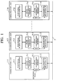
- FIG.1 shows a configuration of a communication system according to the embodiment of the present invention.
- This communication system is constructed such that a plurality of communication units 1-1 to 1-n are connected to a bus 3 so as to exchange data communication mutually.
- Respective communication units 1-1 to 1-n comprise functional block portions 5-1 to 5-n, state monitoring portions 7-1 to 7-n, state information memories 9-1 to 9-n, and transmitting/receiving interfaces (transmitting/receiving I/F) 11-1 to 11-n.
- the communication units 1-1, 1-3 to 1-15 are report communication units for reporting the state information.
- the communication unit 1-2 is a collecting communication unit which collects the state information indicating states of respective communication units 1-1, 1-3 to 1-15.
- the functional block portions 5-1 to 5-n operate as device functions such as a compact disk (CD) player, a mini disk (MD) player, a digital video disk (DVD) player, etc. and have the state information such as CD data, MD data, DVD data, etc.
- the state information memories 9-1 to 9-n store report flags RF for reporting change in the state information to the communication unit 1-2 (collecting communication unit).
- the state monitoring portions 7-1 to 7-n monitor whether or not the state information of the functional block portions 5-1 to 5-n are changed. When the state information are changed, the state monitoring portions 7-1 to 7-n rewrite the state information stored in the state information memories 9-1 to 9-n and also set the report flag RF to "1".
- the transmitting/receiving I/F 11-1 to 11-n Upon receiving, from other communication units, the recovery command for recovering the state information of the communication units 1-1, 1-3 to 1-15 to the communication unit 1-2 serving as the collection destination, the transmitting/receiving I/F 11-1 to 11-n reset the report flag stored in the state information memories 9-1 to 9-n, then add the state information and their own addresses stored in the state information memories 9-1 to 9-n to the recovery command, and then transmit them.
- the report flag is reset to "0" at initial state.
- the report flag is set to "1" when the state information is changed and then reset to "0" when the state information is recovered by the recovery command.
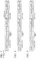
- FIG.3 shows a configuration of the recovery command identified by a source address.
- the recovery command shown in FIG.3 comprises an address area, a command area, and a data area.
- the address area includes a source address having an identification flag IDF indicating that this command is the recovery command, and a destination address.
- the command area includes a command.
- the data area includes a plurality of information areas each of which has a set of its own address, state information, and a write flag WF.
- the write flag WF has been reset at initial state and then set at the time when the state information and own address are written. If the write flag WF is set, writing of corresponding state information and own address is inhibited to thus prevent overwriting.
- Identification of the recovery command is not limited to the case where the identification flag is employed.
- the recovery command may be identified only when the source address indicates a particular source.
- the state monitoring portion 7-1 decides whether or not the state information in the functional block portion 5-1 has been changed (step S11).
- the state monitoring portion 7-1 rewrites the state information stored in the state information memory 9-1 and also sets the report flag RF added to the state information memory 9-1 to "1" (step S13).
- the transmitting/receiving I/F 11-1 decides whether or not the data is the recovery command (step S15).
- the identification flag IDF is included in the source address shown in FIG.3, the received data can be identified as the recovery command.
- the transmitting/receiving I/F 11-1 resets the report flag RF to "0" (step S17).
- the transmitting/receiving I/F 11-1 writes its own address and the state information into the first information area of the data area of the recovery command not to overwrite them, then sets the corresponding write flag WF, and then transmits the recovery command to the communication unit 1-3 (step S19). Finally, it is decided whether or not the process is to be continued (step S21). If the process is to be continued, the process returns to step S11.
- the transmitting/receiving I/F 11-3 of the communication unit 1-3 receives the recovery command from the communication unit 1-1.
- the processes are carried out in accordance with the flowchart shown in FIG.2. If the state information has been changed, the processes from step S11 to step S19 are executed in the communication unit 1-3. In other words, the transmitting/receiving I/F 11-3 writes its own address and the state information into the second information area of the data area of the recovery command not to overwrite them, then sets the corresponding write flag WF, and then transmits the recovery command to the communication unit 1-4.
- the recovery command is transmitted in the order of the communication units 1-5, 1-6,..., 1-n. If the state information have been changed in respective communication units, the transmitting/receiving I/Fs write their own addresses and the state information into the information areas of the data area of the recovery command not to overwrite them, then set the write flags WF, and then transmit the recovery command to the succeeding communication unit.
- the transmitting/receiving I/F 11-n writes its own address and the state information into the last information areas of the data area of the recovery command not to overwrite them, then sets the write flags WF, and then transmit the recovery command shown in FIG.3 to the communication unit 1-2 serving as the collection destination.
- the transmitting/ receiving I/F 11-2 receives the recovery command from the communication unit 1-n, and stores respective state information in the received recovery command into the state information memory 9-2.
- the state information in the state information memories are rewritten and the report flags are set.
- the report flag is reset, then its own address and the state information are added to the recovery command, and then they are transmitted.
- the state information included in the recovery command in respective communication units can be transmitted to the communication unit 1-2 by transmitting the recovery command only once from the last communication unit 1-n. Therefore, collision of the state information from respective communication units can be avoided.
- a recovery time can be reduced shorter than the case where the state information in all the communication units are to be recovered.
- FIG.4 shows a configuration of the recovery command identified by the destination address.
- the recovery command shown in FIG.4 comprises an address area, a command area, and a data area.
- the address area includes a source address, and a destination address having an identification flag IDF indicating that this command is the recovery command.
- the command area includes a command.
- the data area includes a plurality of information areas each of which has a set of its own address, state information, and a write flag WF.
- the transmitting/receiving I/Fs 11-1 to 11-n receive the recovery command, they can identify that the data is the recovery command, by decoding the identification flag IDF added to the destination address of the recovery command.
- FIG.5 shows a configuration of the recovery command
- the address area includes a source address, and a destination address.
- the command area includes a command having an identification flag IDF indicating that this command is the recovery command.
- the data area includes a plurality of information areas each of which has a set of its own address, state information, and a write flag WF.
- the transmitting/receiving I/Fs 11-1 to 11-n receive the recovery command, they can identify that the data is the recovery command, by decoding the identification flag IDF added to the command of the recovery command.
- Identification of the recovery command is not limited to the case where the identification flag is employed.
- the recovery command may be identified only when the command indicates a predetermined command.
- the communication unit 1-2 has been designated as the collection destination in the above embodiment, any one of other communication units 1-1, 1-3 to 1-n may be employed as the collection destination.
- the state information of their own communication units are stored into the memory portion, then it is monitored whether or not the state information have been changed, then the state information stored in the memory portions are rewritten into the changed state information when the state information have been changed, and then the state information and their own addresses after the change are added to the recovery command to be transmitted when they receive the recovery command.
- the collecting communication unit can receive the recovery command to which the state information and their own addresses in respective report communication units after the change are added collectively.
- the collecting communication unit can acquire the state information of respective report communication units by receiving the recovery command only once, the communication traffic volume can be reduced and also collision of the state information sent out from respective report communication units can be avoided.
- the report flag is set when the state information has been changed and the report flag is reset when the state information and the their own addresses after the change are added to the recovery command, so that it can be grasped whether or not the state information after the change have been recovered.
Landscapes
- Engineering & Computer Science (AREA)
- Computer Networks & Wireless Communication (AREA)
- Signal Processing (AREA)
- Automation & Control Theory (AREA)
- Multimedia (AREA)
- Small-Scale Networks (AREA)
- Computer And Data Communications (AREA)
- Selective Calling Equipment (AREA)
- Maintenance And Management Of Digital Transmission (AREA)
- Data Exchanges In Wide-Area Networks (AREA)
- Communication Control (AREA)
Applications Claiming Priority (3)
| Application Number | Priority Date | Filing Date | Title |
|---|---|---|---|
| JP11842497A JP3977484B2 (ja) | 1997-05-08 | 1997-05-08 | 状態情報の管理方法及び通信システム |
| JP118424/97 | 1997-05-08 | ||
| JP11842497 | 1997-05-08 |
Publications (3)
| Publication Number | Publication Date |
|---|---|
| EP0877322A2 true EP0877322A2 (de) | 1998-11-11 |
| EP0877322A3 EP0877322A3 (de) | 2004-02-04 |
| EP0877322B1 EP0877322B1 (de) | 2006-03-15 |
Family
ID=14736308
Family Applications (1)
| Application Number | Title | Priority Date | Filing Date |
|---|---|---|---|
| EP98108339A Expired - Lifetime EP0877322B1 (de) | 1997-05-08 | 1998-05-07 | Zustandinformationverwaltungsverfahren und Übertragungssystem |
Country Status (4)
| Country | Link |
|---|---|
| US (1) | US6243830B1 (de) |
| EP (1) | EP0877322B1 (de) |
| JP (1) | JP3977484B2 (de) |
| DE (1) | DE69833816T2 (de) |
Cited By (5)
| Publication number | Priority date | Publication date | Assignee | Title |
|---|---|---|---|---|
| WO2005124568A1 (en) | 2004-06-15 | 2005-12-29 | Hms Industrial Networks Ab | Status indicator |
| EP1390857A4 (de) * | 2001-04-26 | 2006-08-23 | Boeing Co | System, verfahren und bussteuerungen zur erzeugung eines event-triggers auf einem netzwerkbus |
| WO2006110932A1 (de) * | 2005-04-18 | 2006-10-26 | Fts Computertechnik Gmbh | Verfahren zur energiesparenden und rechtzeitigen übertragung von ereignisnachrichten |
| US7277970B2 (en) | 2000-12-08 | 2007-10-02 | The Boeing Company | Network device interface for digitally interfacing data channels to a controller via a network |
| US9094369B2 (en) | 2006-01-12 | 2015-07-28 | Samsung Electronics Co., Ltd. | Method and apparatus for storing and restoring state information of remote user interface |
Families Citing this family (14)
| Publication number | Priority date | Publication date | Assignee | Title |
|---|---|---|---|---|
| US7302634B2 (en) | 2001-03-14 | 2007-11-27 | Microsoft Corporation | Schema-based services for identity-based data access |
| US7539747B2 (en) * | 2001-03-14 | 2009-05-26 | Microsoft Corporation | Schema-based context service |
| US6823369B2 (en) * | 2001-03-14 | 2004-11-23 | Microsoft Corporation | Using state information in requests that are transmitted in a distributed network environment |
| US20020133535A1 (en) * | 2001-03-14 | 2002-09-19 | Microsoft Corporation | Identity-centric data access |
| US7024662B2 (en) | 2001-03-14 | 2006-04-04 | Microsoft Corporation | Executing dynamically assigned functions while providing services |
| US9886309B2 (en) | 2002-06-28 | 2018-02-06 | Microsoft Technology Licensing, Llc | Identity-based distributed computing for device resources |
| US6700483B2 (en) | 2002-07-12 | 2004-03-02 | Honeywell International Inc. | Alarm recovery method and system using two notification messages |
| US20040250155A1 (en) * | 2003-05-19 | 2004-12-09 | Stefan Weichselbaum | Aspect based recovery system and method |
| CN1918879B (zh) * | 2004-02-19 | 2014-06-25 | 艾利森电话股份有限公司 | 用于状态存储器管理的方法和装置 |
| US7403204B2 (en) * | 2004-08-23 | 2008-07-22 | Hewlett-Packard Development Company, L.P. | Method and apparatus for managing changes in a virtual screen buffer |
| US7770057B1 (en) * | 2005-10-27 | 2010-08-03 | Symantec Operating Corporation | System and method for customized disaster recovery reports |
| JP4632095B2 (ja) * | 2007-03-07 | 2011-02-16 | 日本電気株式会社 | デバイス状態確認システム、周辺制御処理装置、デバイス、デバイス状態確認方法、及びプログラム |
| JP5516402B2 (ja) * | 2008-08-21 | 2014-06-11 | 富士通株式会社 | 情報処理装置及び情報処理装置の制御方法 |
| CN119741770B (zh) * | 2024-12-16 | 2026-07-03 | 广州小鹏汽车科技有限公司 | 一种车辆数字钥匙的监控系统、监控方法、设备及介质 |
Family Cites Families (16)
| Publication number | Priority date | Publication date | Assignee | Title |
|---|---|---|---|---|
| DE3329228A1 (de) * | 1983-08-12 | 1985-02-21 | Siemens AG, 1000 Berlin und 8000 München | Datenuebertragungsverfahren in einem digitalen uebertragungsnetzwerk und vorrichtung zur durchfuehrung des verfahrens |
| JPS62194759A (ja) | 1986-02-20 | 1987-08-27 | Nec Corp | ル−プ型通信システムにおける呼制御方式 |
| US4954950A (en) * | 1986-09-17 | 1990-09-04 | International Business Machines Corporation | Terminal communications circuit |
| JPS6424538A (en) | 1987-07-20 | 1989-01-26 | Matsushita Electric Industrial Co Ltd | Communication control system |
| US5113521A (en) * | 1988-03-18 | 1992-05-12 | Digital Equipment Corporation | Method and apparatus for handling faults of vector instructions causing memory management exceptions |
| JPH0338784A (ja) | 1989-07-05 | 1991-02-19 | Mitsubishi Electric Corp | パターンジェネレータ |
| US5325376A (en) * | 1990-02-23 | 1994-06-28 | Canon Kabushiki Kaisha | Communication system for detecting a communication error in information transmitted between a plurality of units and a main control unit |
| GB9007600D0 (en) * | 1990-04-04 | 1990-05-30 | Hunting Communication Tech | Ring communication system |
| GB9106113D0 (en) * | 1991-03-22 | 1991-05-08 | D2B Systems Co Ltd | Local communication bus system and apparatus for use in such a system |
| ES2130150T3 (es) | 1991-03-22 | 1999-07-01 | D2B Systems Co Ltd | Sistema de bus de comunicacion local y aparatos para su uso en un sistema de este tipo. |
| JPH05160841A (ja) * | 1991-12-09 | 1993-06-25 | Matsushita Electric Ind Co Ltd | 状態情報返答方法 |
| US5758053A (en) * | 1992-07-22 | 1998-05-26 | Hitachi, Ltd. | Fault handling and recovery for system having plural processors |
| US5740231A (en) * | 1994-09-16 | 1998-04-14 | Octel Communications Corporation | Network-based multimedia communications and directory system and method of operation |
| US5802320A (en) * | 1995-05-18 | 1998-09-01 | Sun Microsystems, Inc. | System for packet filtering of data packets at a computer network interface |
| US5696895A (en) * | 1995-05-19 | 1997-12-09 | Compaq Computer Corporation | Fault tolerant multiple network servers |
| FR2739510A1 (fr) * | 1995-10-02 | 1997-04-04 | Canon Kk | Convertisseur de communication, appareils de communication, procede d'identification, procede de transmission de trames et systemes de communication les mettant en oeuvre |
-
1997
- 1997-05-08 JP JP11842497A patent/JP3977484B2/ja not_active Expired - Lifetime
-
1998
- 1998-05-06 US US09/072,980 patent/US6243830B1/en not_active Expired - Fee Related
- 1998-05-07 DE DE69833816T patent/DE69833816T2/de not_active Expired - Fee Related
- 1998-05-07 EP EP98108339A patent/EP0877322B1/de not_active Expired - Lifetime
Cited By (6)
| Publication number | Priority date | Publication date | Assignee | Title |
|---|---|---|---|---|
| US7277970B2 (en) | 2000-12-08 | 2007-10-02 | The Boeing Company | Network device interface for digitally interfacing data channels to a controller via a network |
| EP1390857A4 (de) * | 2001-04-26 | 2006-08-23 | Boeing Co | System, verfahren und bussteuerungen zur erzeugung eines event-triggers auf einem netzwerkbus |
| US7346719B2 (en) | 2001-04-26 | 2008-03-18 | The Boeing Company | Systems, methods, and bus controllers for creating an event trigger on a network bus |
| WO2005124568A1 (en) | 2004-06-15 | 2005-12-29 | Hms Industrial Networks Ab | Status indicator |
| WO2006110932A1 (de) * | 2005-04-18 | 2006-10-26 | Fts Computertechnik Gmbh | Verfahren zur energiesparenden und rechtzeitigen übertragung von ereignisnachrichten |
| US9094369B2 (en) | 2006-01-12 | 2015-07-28 | Samsung Electronics Co., Ltd. | Method and apparatus for storing and restoring state information of remote user interface |
Also Published As
| Publication number | Publication date |
|---|---|
| JP3977484B2 (ja) | 2007-09-19 |
| EP0877322A3 (de) | 2004-02-04 |
| DE69833816T2 (de) | 2006-10-05 |
| DE69833816D1 (de) | 2006-05-11 |
| EP0877322B1 (de) | 2006-03-15 |
| JPH10307779A (ja) | 1998-11-17 |
| US6243830B1 (en) | 2001-06-05 |
Similar Documents
| Publication | Publication Date | Title |
|---|---|---|
| US6243830B1 (en) | State information managing method and communication system | |
| EP0885418B1 (de) | Asynchrones datenübertragungsgerät zur verwaltung asynchroner datenübertragungen zwischen einem anwendungsprogramm und einer busstruktur | |
| US6854054B1 (en) | System and method of memory management for providing data storage across a reboot | |
| US6615314B1 (en) | Disk array and method for reading/writing data from/into disk unit | |
| US20140241148A1 (en) | Failure recovery method in non revertive mode of ethernet ring network | |
| JP3803250B2 (ja) | バスマスター切換ユニット | |
| JP2001515309A (ja) | ローカル通信システムおよびその中で使用される装置 | |
| CN100585693C (zh) | 对象操作装置、对象操作方法和信息处理装置 | |
| JP2000307624A (ja) | 送信情報中継システム及びその中継装置 | |
| US6829228B2 (en) | Information transfer method radio terminal and radio gateway device using datalink layer signaling of protocol indentifier | |
| US5590117A (en) | Node information collecting method in a ring system | |
| JPH11512540A (ja) | デュプレックスコンピュータ装置の共用ディスクデータの制御 | |
| US6167454A (en) | Address setting method and communication system employing the address setting method in a multiple ring network utilizing variably set addresses and address write enable/disable states | |
| JP2001136172A (ja) | 通信ネットワークシステムにおける通信制御方法及び通信ネットワークシステム並びに通信制御処理プログラムを記録した記録媒体 | |
| JP2003204327A (ja) | コンピュータシステムの管理方法、管理プログラム、記憶装置および表示装置 | |
| EP0877321A2 (de) | Zustandinformationsverwaltungsverfahren und System, das dieses Verfahren verwendet | |
| JP2001034510A (ja) | クラッシュダンプ管理装置及びクラッシュダンプ管理方法 | |
| JPH10304021A (ja) | 伝送装置監視制御システムにおけるアラーム履歴管理方式 | |
| JP3534630B2 (ja) | リングネットワークにおける情報管理方法 | |
| JPH0736632B2 (ja) | タイムスロツトシフト制御方式 | |
| JP3107714B2 (ja) | データ伝送装置及びその方法 | |
| JPH06104907A (ja) | ポーリング方式 | |
| JPH10133970A (ja) | ファイル転送システム | |
| JPH06276203A (ja) | ポーリング式データ収集方式 | |
| JPH11341019A (ja) | 多重通信システム |
Legal Events
| Date | Code | Title | Description |
|---|---|---|---|
| PUAI | Public reference made under article 153(3) epc to a published international application that has entered the european phase |
Free format text: ORIGINAL CODE: 0009012 |
|
| 17P | Request for examination filed |
Effective date: 19980507 |
|
| AK | Designated contracting states |
Kind code of ref document: A2 Designated state(s): AT BE CH CY DE DK ES FI FR GB GR IE IT LI LU MC NL PT SE |
|
| AX | Request for extension of the european patent |
Free format text: AL;LT;LV;MK;RO;SI |
|
| PUAL | Search report despatched |
Free format text: ORIGINAL CODE: 0009013 |
|
| RIC1 | Information provided on ipc code assigned before grant |
Ipc: 7H 04L 12/403 B Ipc: 7H 04L 12/40 B Ipc: 7G 06F 13/42 B Ipc: 7G 06F 13/38 A |
|
| AK | Designated contracting states |
Kind code of ref document: A3 Designated state(s): AT BE CH CY DE DK ES FI FR GB GR IE IT LI LU MC NL PT SE |
|
| AX | Request for extension of the european patent |
Extension state: AL LT LV MK RO SI |
|
| 17Q | First examination report despatched |
Effective date: 20040723 |
|
| AKX | Designation fees paid |
Designated state(s): DE FR GB |
|
| GRAP | Despatch of communication of intention to grant a patent |
Free format text: ORIGINAL CODE: EPIDOSNIGR1 |
|
| GRAS | Grant fee paid |
Free format text: ORIGINAL CODE: EPIDOSNIGR3 |
|
| GRAA | (expected) grant |
Free format text: ORIGINAL CODE: 0009210 |
|
| AK | Designated contracting states |
Kind code of ref document: B1 Designated state(s): DE FR GB |
|
| REG | Reference to a national code |
Ref country code: GB Ref legal event code: FG4D |
|
| REF | Corresponds to: |
Ref document number: 69833816 Country of ref document: DE Date of ref document: 20060511 Kind code of ref document: P |
|
| PGFP | Annual fee paid to national office [announced via postgrant information from national office to epo] |
Ref country code: FR Payment date: 20060522 Year of fee payment: 9 Ref country code: DE Payment date: 20060522 Year of fee payment: 9 |
|
| PGFP | Annual fee paid to national office [announced via postgrant information from national office to epo] |
Ref country code: GB Payment date: 20060525 Year of fee payment: 9 |
|
| ET | Fr: translation filed | ||
| PLBE | No opposition filed within time limit |
Free format text: ORIGINAL CODE: 0009261 |
|
| STAA | Information on the status of an ep patent application or granted ep patent |
Free format text: STATUS: NO OPPOSITION FILED WITHIN TIME LIMIT |
|
| 26N | No opposition filed |
Effective date: 20061218 |
|
| GBPC | Gb: european patent ceased through non-payment of renewal fee |
Effective date: 20070507 |
|
| REG | Reference to a national code |
Ref country code: FR Ref legal event code: ST Effective date: 20080131 |
|
| PG25 | Lapsed in a contracting state [announced via postgrant information from national office to epo] |
Ref country code: DE Free format text: LAPSE BECAUSE OF NON-PAYMENT OF DUE FEES Effective date: 20071201 |
|
| PG25 | Lapsed in a contracting state [announced via postgrant information from national office to epo] |
Ref country code: GB Free format text: LAPSE BECAUSE OF NON-PAYMENT OF DUE FEES Effective date: 20070507 |
|
| PG25 | Lapsed in a contracting state [announced via postgrant information from national office to epo] |
Ref country code: FR Free format text: LAPSE BECAUSE OF NON-PAYMENT OF DUE FEES Effective date: 20070531 |