EP0882505A2 - Honigwaben Katalysator und Verfahren zu seiner Herstellung - Google Patents
Honigwaben Katalysator und Verfahren zu seiner Herstellung Download PDFInfo
- Publication number
- EP0882505A2 EP0882505A2 EP98108150A EP98108150A EP0882505A2 EP 0882505 A2 EP0882505 A2 EP 0882505A2 EP 98108150 A EP98108150 A EP 98108150A EP 98108150 A EP98108150 A EP 98108150A EP 0882505 A2 EP0882505 A2 EP 0882505A2
- Authority
- EP
- European Patent Office
- Prior art keywords
- catalyst
- honeycomb
- mold
- manufacturing
- irregularities
- Prior art date
- Legal status (The legal status is an assumption and is not a legal conclusion. Google has not performed a legal analysis and makes no representation as to the accuracy of the status listed.)
- Granted
Links
Images



Classifications
-
- B—PERFORMING OPERATIONS; TRANSPORTING
- B28—WORKING CEMENT, CLAY, OR STONE
- B28B—SHAPING CLAY OR OTHER CERAMIC COMPOSITIONS; SHAPING SLAG; SHAPING MIXTURES CONTAINING CEMENTITIOUS MATERIAL, e.g. PLASTER
- B28B3/00—Producing shaped articles from the material by using presses; Presses specially adapted therefor
- B28B3/20—Producing shaped articles from the material by using presses; Presses specially adapted therefor wherein the material is extruded
- B28B3/26—Extrusion dies
- B28B3/269—For multi-channeled structures, e.g. honeycomb structures
-
- B—PERFORMING OPERATIONS; TRANSPORTING
- B01—PHYSICAL OR CHEMICAL PROCESSES OR APPARATUS IN GENERAL
- B01J—CHEMICAL OR PHYSICAL PROCESSES, e.g. CATALYSIS OR COLLOID CHEMISTRY; THEIR RELEVANT APPARATUS
- B01J35/00—Catalysts, in general, characterised by their form or physical properties
- B01J35/50—Catalysts, in general, characterised by their form or physical properties characterised by their shape or configuration
- B01J35/56—Foraminous structures having flow-through passages or channels, e.g. grids or three-dimensional [3D] monoliths
- B01J35/57—Honeycombs
-
- B—PERFORMING OPERATIONS; TRANSPORTING
- B01—PHYSICAL OR CHEMICAL PROCESSES OR APPARATUS IN GENERAL
- B01D—SEPARATION
- B01D53/00—Separation of gases or vapours; Recovering vapours of volatile solvents from gases; Chemical or biological purification of waste gases, e.g. engine exhaust gases, smoke, fumes, flue gases, aerosols
- B01D53/34—Chemical or biological purification of waste gases
- B01D53/74—General processes for purification of waste gases; Apparatus or devices specially adapted therefor
- B01D53/86—Catalytic processes
- B01D53/88—Handling or mounting catalysts
- B01D53/885—Devices in general for catalytic purification of waste gases
-
- B—PERFORMING OPERATIONS; TRANSPORTING
- B01—PHYSICAL OR CHEMICAL PROCESSES OR APPARATUS IN GENERAL
- B01D—SEPARATION
- B01D53/00—Separation of gases or vapours; Recovering vapours of volatile solvents from gases; Chemical or biological purification of waste gases, e.g. engine exhaust gases, smoke, fumes, flue gases, aerosols
- B01D53/34—Chemical or biological purification of waste gases
- B01D53/92—Chemical or biological purification of waste gases of engine exhaust gases
- B01D53/94—Chemical or biological purification of waste gases of engine exhaust gases by catalytic processes
- B01D53/9404—Removing only nitrogen compounds
- B01D53/9409—Nitrogen oxides
- B01D53/9431—Processes characterised by a specific device
-
- B—PERFORMING OPERATIONS; TRANSPORTING
- B01—PHYSICAL OR CHEMICAL PROCESSES OR APPARATUS IN GENERAL
- B01J—CHEMICAL OR PHYSICAL PROCESSES, e.g. CATALYSIS OR COLLOID CHEMISTRY; THEIR RELEVANT APPARATUS
- B01J37/00—Processes, in general, for preparing catalysts; Processes, in general, for activation of catalysts
- B01J37/0009—Use of binding agents; Moulding; Pressing; Powdering; Granulating; Addition of materials ameliorating the mechanical properties of the product catalyst
-
- F—MECHANICAL ENGINEERING; LIGHTING; HEATING; WEAPONS; BLASTING
- F01—MACHINES OR ENGINES IN GENERAL; ENGINE PLANTS IN GENERAL; STEAM ENGINES
- F01N—GAS-FLOW SILENCERS OR EXHAUST APPARATUS FOR MACHINES OR ENGINES IN GENERAL; GAS-FLOW SILENCERS OR EXHAUST APPARATUS FOR INTERNAL-COMBUSTION ENGINES
- F01N3/00—Exhaust or silencing apparatus having means for purifying, rendering innocuous, or otherwise treating exhaust
- F01N3/08—Exhaust or silencing apparatus having means for purifying, rendering innocuous, or otherwise treating exhaust for rendering innocuous
- F01N3/10—Exhaust or silencing apparatus having means for purifying, rendering innocuous, or otherwise treating exhaust for rendering innocuous by thermal or catalytic conversion of noxious components of exhaust
- F01N3/24—Exhaust or silencing apparatus having means for purifying, rendering innocuous, or otherwise treating exhaust for rendering innocuous by thermal or catalytic conversion of noxious components of exhaust characterised by constructional aspects of converting apparatus
- F01N3/28—Construction of catalytic reactors
- F01N3/2803—Construction of catalytic reactors characterised by structure, by material or by manufacturing of catalyst support
- F01N3/2825—Ceramics
-
- F—MECHANICAL ENGINEERING; LIGHTING; HEATING; WEAPONS; BLASTING
- F01—MACHINES OR ENGINES IN GENERAL; ENGINE PLANTS IN GENERAL; STEAM ENGINES
- F01N—GAS-FLOW SILENCERS OR EXHAUST APPARATUS FOR MACHINES OR ENGINES IN GENERAL; GAS-FLOW SILENCERS OR EXHAUST APPARATUS FOR INTERNAL-COMBUSTION ENGINES
- F01N2330/00—Structure of catalyst support or particle filter
- F01N2330/30—Honeycomb supports characterised by their structural details
- F01N2330/38—Honeycomb supports characterised by their structural details flow channels with means to enhance flow mixing,(e.g. protrusions or projections)
-
- Y—GENERAL TAGGING OF NEW TECHNOLOGICAL DEVELOPMENTS; GENERAL TAGGING OF CROSS-SECTIONAL TECHNOLOGIES SPANNING OVER SEVERAL SECTIONS OF THE IPC; TECHNICAL SUBJECTS COVERED BY FORMER USPC CROSS-REFERENCE ART COLLECTIONS [XRACs] AND DIGESTS
- Y10—TECHNICAL SUBJECTS COVERED BY FORMER USPC
- Y10T—TECHNICAL SUBJECTS COVERED BY FORMER US CLASSIFICATION
- Y10T428/00—Stock material or miscellaneous articles
- Y10T428/12—All metal or with adjacent metals
- Y10T428/12333—Helical or with helical component
-
- Y—GENERAL TAGGING OF NEW TECHNOLOGICAL DEVELOPMENTS; GENERAL TAGGING OF CROSS-SECTIONAL TECHNOLOGIES SPANNING OVER SEVERAL SECTIONS OF THE IPC; TECHNICAL SUBJECTS COVERED BY FORMER USPC CROSS-REFERENCE ART COLLECTIONS [XRACs] AND DIGESTS
- Y10—TECHNICAL SUBJECTS COVERED BY FORMER USPC
- Y10T—TECHNICAL SUBJECTS COVERED BY FORMER US CLASSIFICATION
- Y10T428/00—Stock material or miscellaneous articles
- Y10T428/24—Structurally defined web or sheet [e.g., overall dimension, etc.]
- Y10T428/24744—Longitudinal or transverse tubular cavity or cell
Definitions
- the present invention relates to a honeycomb catalyst and a manufacturing method therefor and, more particularly, to a honeycomb catalyst having an improved gas contact efficiency and a manufacturing method therefor.
- Honeycomb catalysts having a grid-like or beehive-like opening have widely been used as catalysts for reaction with various gases such as NOx removal catalysts for boiler exhaust gas and gas turbine exhaust gas of various fuels or catalysts for treating automotive exhaust gas because they can maintain a low pressure loss when gas flows through and comes into contact with the catalyst and because clogging can be avoided in treatment of gas containing dust.
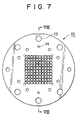
- the honeycomb catalyst used here is conventionally manufactured as follows: For example, for an NOx removal catalyst, a solution of compound of V, Mo, W, etc., which are active components, an organic binder, and an inorganic binder are mixed with TiO 2 powder, which is a catalyst raw material, and the mixture is kneaded into a clay-like substance, and then a molded product having a grid-like opening is obtained by using an extrusion molding machine provided with a mold 10, for example, as shown in FIGS. 7 and 8.
- FIG. 7 is a front view
- FIG. 8 is a sectional view taken along the line VIII-VIII of FIG. 7.
- the clay-like substance containing a catalyst component passes through a clay-like substance passing hole 12 from B side toward C side in FIG.
- Reference numeral 13 in FIGS. 7, 8 denotes a bolt hole for attaching a mouthpiece 10 to an extruder, and 14 denotes a bolt hole for attaching a die forming an external frame.
- honeycomb catalyst has excellent structural features as described above, a honeycomb catalyst which has an improved gas contact efficiency has been demanded to carry out gas reaction or gas treatment more efficiently.
- the present invention was made in view of the above situation, and accordingly an object thereof is to provide a honeycomb catalyst having an improved gas contact efficiency and a manufacturing method therefor.
- the inventors intensively studied the rate of a reaction using a honeycomb catalyst.
- the important factors are the gas contact area per unit volume of catalyst and the travel velocity of reaction substance to the honeycomb wall surface, and in order to achieve the catalyst performance effectively, the increase in contact area and the increase in travel velocity of reaction substance to the wall surface achieved by making the gas flow in the honeycomb hole turbulent are effective, with the result that the present invention was completed.
- the present invention provides a honeycomb catalyst in which irregularities are formed on a catalyst inside wall in a honeycomb hole.
- a manufacturing method for a honeycomb catalyst by using an extrusion molding method, in which extrusion molding is effected by using a mold having a means for providing irregularities to a catalyst inside wall of a honeycomb hole.
- a means for providing irregularities to a catalyst inside wall of a honeycomb hole is configured so that rollers formed with irregularities with a proper pitch on the surface are mounted on a mouthpiece at the tip end of the mold.
- a means for providing irregularities to a catalyst inside wall of a honeycomb hole is configured so that oscillators oscillating with a constant period are attached to a mouthpiece at the tip end of the mold.
- a means for providing irregularities to a catalyst inside wall of a honeycomb hole is configured so that auxiliary plates having indentations at the edge are attached to a mouthpiece at the tip end of the mold.
- the honeycomb catalyst in accordance with the present invention can widely be used as a catalyst for reaction with various gases such as an NOx removal catalyst for boiler exhaust gas and gas turbine exhaust gas of various fuels or a catalyst for treating automotive exhaust gas.
- various gases such as an NOx removal catalyst for boiler exhaust gas and gas turbine exhaust gas of various fuels or a catalyst for treating automotive exhaust gas.
- it is useful as a catalyst used in the field of the reduction removal of nitrogen oxides contained in a combustion exhaust gas or the removal of unburned carbon monoxide and hydrocarbon.
- the honeycomb catalyst in accordance with the present invention in which irregularities are formed on a catalyst inside wall in a honeycomb hole, has a large contact area with which the gas flowing in the hole comes into contact, has an effect of making the gas flow turbulent in the hole, offers a higher contact efficiency between the catalyst and the reaction gas than the conventional honeycomb catalyst, exhibiting a high catalyst performance.
- a honeycomb catalyst molded by using a conventional mold as shown in FIGS. 7 and 8 has a smooth wall surface in the honeycomb hole thereof. Therefore, the gas which is brought into contact with the catalyst usually passes through the honeycomb holes without the turbulence of flow.
- irregularities are formed on the catalyst inside wall in the honeycomb hole thereof, so that the gas contact area per unit volume of the molded catalyst increases, by which the performance as a catalyst is improved.
- the irregularities are formed so that the cross-sectional area of gas flow path changes in the gas travel direction as in the honeycomb catalyst molded by using a later-described mold shown in FIGS. 1 to 6, the turbulence of gas flow in the honeycomb hole increases, leading to an increase in travel velocity of reaction substance on the gas boundary film, so that the catalyst performance increasing effect is increased.
- the honeycomb catalyst in accordance with the present invention in which irregularities are formed on the catalyst inside wall in the honeycomb hole, can be manufactured by kneading a catalyst constituent raw material with a molding auxiliary, binder component, etc. and by extrusion molding the extrusion raw material (kneaded substance) capable of being extrusion molded by using a mold having a means for providing irregularities to the catalyst inside wall in the honeycomb hole.
- the present invention will be described in more detail with reference to the accompanying drawings.
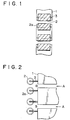
- FIGS. 1 and 2 are views enlargedly showing a part of the tip end of an example of a mold used for manufacturing a catalyst in accordance with the present invention.
- FIG. 1 is a front view
- FIG. 2 is a side view.
- rollers 2 formed with irregularities 2a with a proper pitch on the surface are mounted on a mouthpiece 1 at the tip end of the mold via a roller support 3.
- the kneaded substance extruded from the direction of A in FIG. 2 comes into contact with the roller 2 at an outlet B, so that irregularities corresponding to the irregularities 2a formed on the surface of the roller 2 are formed on the inside wall of the hole of molded catalyst as the roller 2 rotates.
- FIGS. 3 and 4 are views enlargedly showing a part of the tip end of another example of a mold used for manufacturing a catalyst in accordance with the present invention.
- FIG. 3 is a front view
- FIG. 4 is a sectional view taken along the line IV-IV of FIG. 3.
- oscillators 4 which oscillate with a constant period are attached to a mouthpiece 1 at the tip end of the mold.
- the oscillator 4 comes into contact with and is pressed on the kneaded substance extruded from the direction of A in the figure at an outlet B, so that irregularities are formed on the inside wall of the hole of molded catalyst.
- the oscillator 4 is attracted by a magnetic force and is returned by a return spring (not shown), for example, by turning on and off the current flowing in an electromagnet 4a, whereby the oscillator 4 can be oscillated.
- FIGS. 5 and 6 are views enlargedly showing a part of the tip end of still another example of a mold used for manufacturing a catalyst in accordance with the present invention.
- FIG. 5 is a front view
- FIG. 6 is a side view.
- auxiliary plates 5 having indentations at the edge are attached to a mouthpiece 1 at the tip end of the mold so that the cross-sectional shape of the mouthpiece 1 is corrected by the auxiliary plates 5.
- the kneaded substance extruded from the direction of A in FIG. 6 is extruded into a cross-sectional shape corresponding to the shape of the auxiliary plate 5 from the outlet B so that irregularities parallel to the gas flow direction are formed on the inside wall of the hole of molded catalyst.
- Reference numeral 6 in FIGS. 5 and 6 denotes a screw for attaching the auxiliary plate 5 to the tip end of the mouthpiece 1.
- FIGS. 1 to 6 can be configured in the same way as the mold shown in FIGS. 7 and 8 or other publicly-known molds. Also, as the configuration of other portions of an apparatus using such a mold, an apparatus which is publicly known to a person skilled in the art can be used.
Landscapes
- Chemical & Material Sciences (AREA)
- Engineering & Computer Science (AREA)
- Chemical Kinetics & Catalysis (AREA)
- Environmental & Geological Engineering (AREA)
- Health & Medical Sciences (AREA)
- Organic Chemistry (AREA)
- Mechanical Engineering (AREA)
- Oil, Petroleum & Natural Gas (AREA)
- Analytical Chemistry (AREA)
- Materials Engineering (AREA)
- Biomedical Technology (AREA)
- Ceramic Engineering (AREA)
- General Chemical & Material Sciences (AREA)
- Combustion & Propulsion (AREA)
- Toxicology (AREA)
- General Engineering & Computer Science (AREA)
- Manufacturing & Machinery (AREA)
- Catalysts (AREA)
- Press-Shaping Or Shaping Using Conveyers (AREA)
- Exhaust Gas After Treatment (AREA)
Applications Claiming Priority (3)
| Application Number | Priority Date | Filing Date | Title |
|---|---|---|---|
| JP14914497A JP4220584B2 (ja) | 1997-06-06 | 1997-06-06 | ハニカム型触媒の製造方法 |
| JP149144/97 | 1997-06-06 | ||
| JP14914497 | 1997-06-06 |
Publications (3)
| Publication Number | Publication Date |
|---|---|
| EP0882505A2 true EP0882505A2 (de) | 1998-12-09 |
| EP0882505A3 EP0882505A3 (de) | 1999-04-14 |
| EP0882505B1 EP0882505B1 (de) | 2003-01-29 |
Family
ID=15468737
Family Applications (1)
| Application Number | Title | Priority Date | Filing Date |
|---|---|---|---|
| EP98108150A Expired - Lifetime EP0882505B1 (de) | 1997-06-06 | 1998-05-05 | Verfahren zur Herstellung eines Wabenkörper-Katalysators |
Country Status (8)
| Country | Link |
|---|---|
| US (1) | US6156698A (de) |
| EP (1) | EP0882505B1 (de) |
| JP (1) | JP4220584B2 (de) |
| KR (1) | KR100278897B1 (de) |
| AT (1) | ATE231741T1 (de) |
| CA (1) | CA2239700C (de) |
| DE (1) | DE69810992T2 (de) |
| DK (1) | DK0882505T3 (de) |
Families Citing this family (65)
| Publication number | Priority date | Publication date | Assignee | Title |
|---|---|---|---|---|
| USD442612S1 (en) | 2000-04-17 | 2001-05-22 | Jmp Industries, Inc. | Extruder plate for diamond shaped extruder insert |
| USD444487S1 (en) | 2000-04-17 | 2001-07-03 | Jmp Industries, Inc. | Diamond shape extruder insert |
| DE10024038A1 (de) * | 2000-05-13 | 2001-11-22 | Dmc2 Degussa Metals Catalysts | Wabenkörper aus einem keramischen Material mit verbesserter radialer Druckfestigkeit |
| USD446794S1 (en) | 2000-09-20 | 2001-08-21 | Jmp Industries, Inc. | Mesh ring extruder die |
| USD450732S1 (en) | 2001-02-16 | 2001-11-20 | Jmp Industries, Inc. | Extruder plate for diamond shaped extruder insert |
| USD452257S1 (en) | 2001-07-25 | 2001-12-18 | J M P Industries, Inc. | Extruder plate for diamond shaped extruder insert |
| USD472252S1 (en) | 2002-02-01 | 2003-03-25 | Jmp Industries, Inc. | Mesh ring extruder die |
| USD469452S1 (en) | 2002-02-04 | 2003-01-28 | Jmp Industries, Inc. | Diamond shape extruder insert |
| USD469117S1 (en) | 2002-02-04 | 2003-01-21 | Jmp Industries, Inc. | Diamond shape extruder insert |
| USD470870S1 (en) | 2002-04-09 | 2003-02-25 | Jmp Industries, Inc. | Diamond shape extruder insert |
| USD469454S1 (en) | 2002-04-09 | 2003-01-28 | Jmp Industries, Inc. | Extruder plate for diamond shaped extruder insert |
| USD470869S1 (en) | 2002-04-09 | 2003-02-25 | Jmp Industries, Inc. | Diamond shape extruder insert |
| USD469116S1 (en) | 2002-04-09 | 2003-01-21 | Jmp Industries, Inc. | Extruder plate for diamond shaped extruder insert |
| USD469453S1 (en) | 2002-04-09 | 2003-01-28 | Jmp Industries, Inc. | Extruder plate for diamond shaped extruder insert |
| US7582270B2 (en) | 2002-10-28 | 2009-09-01 | Geo2 Technologies, Inc. | Multi-functional substantially fibrous mullite filtration substrates and devices |
| US6946013B2 (en) | 2002-10-28 | 2005-09-20 | Geo2 Technologies, Inc. | Ceramic exhaust filter |
| US7572311B2 (en) | 2002-10-28 | 2009-08-11 | Geo2 Technologies, Inc. | Highly porous mullite particulate filter substrate |
| US7574796B2 (en) | 2002-10-28 | 2009-08-18 | Geo2 Technologies, Inc. | Nonwoven composites and related products and methods |
| USD485286S1 (en) | 2003-01-07 | 2004-01-13 | Jmp Industries, Inc. | Extruder plate for diamond shaped extruder insert |
| US8580211B2 (en) * | 2003-05-16 | 2013-11-12 | Velocys, Inc. | Microchannel with internal fin support for catalyst or sorption medium |
| USD497376S1 (en) | 2003-08-29 | 2004-10-19 | Jmp Industries, Inc. | Extruder plate for diamond shaped extruder insert |
| USD494198S1 (en) | 2003-08-29 | 2004-08-10 | Jmp Industries, Inc. | Extruder plate for diamond shaped extruder insert |
| US9023900B2 (en) | 2004-01-28 | 2015-05-05 | Velocys, Inc. | Fischer-Tropsch synthesis using microchannel technology and novel catalyst and microchannel reactor |
| US7084180B2 (en) * | 2004-01-28 | 2006-08-01 | Velocys, Inc. | Fischer-tropsch synthesis using microchannel technology and novel catalyst and microchannel reactor |
| USD544005S1 (en) | 2006-07-14 | 2007-06-05 | James M. Pinchot | Extruder insert |
| US8186991B2 (en) | 2004-02-27 | 2012-05-29 | Jmp Industries, Inc. | Extruder system and cutting assembly |
| USD523452S1 (en) | 2004-06-01 | 2006-06-20 | James M. Pinchot | Extruder plate for diamond shaped extruder insert |
| US7211232B1 (en) | 2005-11-07 | 2007-05-01 | Geo2 Technologies, Inc. | Refractory exhaust filtering method and apparatus |
| US7682578B2 (en) | 2005-11-07 | 2010-03-23 | Geo2 Technologies, Inc. | Device for catalytically reducing exhaust |
| US7682577B2 (en) | 2005-11-07 | 2010-03-23 | Geo2 Technologies, Inc. | Catalytic exhaust device for simplified installation or replacement |
| USD534562S1 (en) | 2005-11-10 | 2007-01-02 | James M. Pinchot | Extruder plate for diamond shaped extruder insert |
| US7722828B2 (en) | 2005-12-30 | 2010-05-25 | Geo2 Technologies, Inc. | Catalytic fibrous exhaust system and method for catalyzing an exhaust gas |
| US7444805B2 (en) | 2005-12-30 | 2008-11-04 | Geo2 Technologies, Inc. | Substantially fibrous refractory device for cleaning a fluid |
| USD531197S1 (en) | 2006-01-27 | 2006-10-31 | Jmp Industries, Inc. | Extruder plate for diamond shaped extruder insert |
| US7563415B2 (en) | 2006-03-03 | 2009-07-21 | Geo2 Technologies, Inc | Catalytic exhaust filter device |
| USD562858S1 (en) | 2007-03-21 | 2008-02-26 | Jmp Industries, Inc. | Extruder plate for generally triangular shaped extruder inserts |
| USD565067S1 (en) | 2007-03-21 | 2008-03-25 | Jmp Industries, Inc. | Extruder plate for generally triangular shaped extruder inserts |
| USD562370S1 (en) | 2007-03-21 | 2008-02-19 | Jmp Industries, Inc. | Extruder plate for generally triangular shaped extruder inserts |
| USD577044S1 (en) | 2007-03-21 | 2008-09-16 | Jmp Industries Inc. | Extruder insert |
| USD563442S1 (en) | 2007-03-21 | 2008-03-04 | Jmp Industries, Inc. | Extruder plate for generally triangular shaped extruder inserts |
| USD573616S1 (en) | 2007-03-21 | 2008-07-22 | Jmp Industries, Inc. | Extruder insert |
| USD564550S1 (en) | 2007-03-21 | 2008-03-18 | Jmp Industries, Inc. | Extruder plate for generally triangular shaped extruder inserts |
| USD564551S1 (en) | 2007-03-21 | 2008-03-18 | Jmp Industries, Inc. | Extruder plate for generally triangular shaped extruder inserts |
| USD562857S1 (en) | 2007-03-21 | 2008-02-26 | Jmp Industries, Inc. | Extruder plate for generally triangular shaped extruder inserts |
| USD562364S1 (en) | 2007-03-21 | 2008-02-19 | Jmp Industries, Inc. | Extruder insert |
| USD577375S1 (en) | 2007-03-21 | 2008-09-23 | Jmp Industries, Inc. | Extruder insert |
| USD568349S1 (en) | 2007-03-21 | 2008-05-06 | Jmp Industries, Inc. | Extruder plate for generally triangular shaped extruder inserts |
| USD565068S1 (en) | 2007-03-21 | 2008-03-25 | Jmp Industries, Inc. | Extruder plate for generally triangular shaped extruder inserts |
| USD563441S1 (en) | 2007-03-21 | 2008-03-04 | Jmp Industries, Inc. | Extruder plate for generally triangular shaped extruder inserts |
| USD569885S1 (en) | 2007-03-21 | 2008-05-27 | Jmp Industries, Inc. | Extruder plate for generally triangular shaped extruder inserts |
| USD565610S1 (en) | 2007-03-21 | 2008-04-01 | Jmp Industries, Inc. | Extruder plate for generally triangular shaped extruder inserts |
| USD566145S1 (en) | 2007-03-21 | 2008-04-08 | Jmp Industries, Inc. | Extruder plate for generally triangular shaped extruder inserts |
| USD565611S1 (en) | 2007-03-21 | 2008-04-01 | Jmp Industries, Inc. | Extruder plate for generally triangular shaped extruder inserts |
| USD562861S1 (en) | 2007-03-21 | 2008-02-26 | Jmp Industries, Inc. | Extruder plate for generally triangular shaped extruder inserts |
| USD577045S1 (en) | 2007-03-21 | 2008-09-16 | Jmp Industries, Inc. | Extruder plate for generally triangular shaped extruder inserts |
| USD565614S1 (en) | 2007-03-21 | 2008-04-01 | Jmp Industries, Inc. | Extruder plate for generally triangular shaped extruder inserts |
| USD562860S1 (en) | 2007-03-21 | 2008-02-26 | Jmp Industries, Inc. | Extruder plate for generally triangular shaped extruder inserts |
| USD564549S1 (en) | 2007-03-21 | 2008-03-18 | Jmp Industries, Inc. | Extruder insert |
| USD562859S1 (en) | 2007-03-21 | 2008-02-26 | Jmp Industries, Inc. | Extruder plate for generally triangular shaped extruder inserts |
| USD565615S1 (en) | 2007-03-21 | 2008-04-01 | Jmp Industries, Inc. | Extruder plate for generally triangular shaped extruder inserts |
| USD573617S1 (en) | 2007-03-21 | 2008-07-22 | Jmp Industries, Inc. | Extruder insert |
| USD577751S1 (en) | 2007-03-21 | 2008-09-30 | Jmp Industries, Inc. | Extruder insert |
| USD565612S1 (en) | 2007-03-21 | 2008-04-01 | Jmp Industries, Inc. | Extruder plate for generally triangular shaped extruder inserts |
| GB201214122D0 (en) | 2012-08-07 | 2012-09-19 | Oxford Catalysts Ltd | Treating of catalyst support |
| WO2016201218A2 (en) | 2015-06-12 | 2016-12-15 | Velocys, Inc. | Synthesis gas conversion process |
Family Cites Families (23)
| Publication number | Priority date | Publication date | Assignee | Title |
|---|---|---|---|---|
| US4404007A (en) * | 1980-12-11 | 1983-09-13 | Nippon Soken, Inc. | Exhaust gas cleaning element |
| US4349450A (en) * | 1981-04-01 | 1982-09-14 | Johnson Matthey, Inc. | Catalytic elements |
| JPS5843238A (ja) * | 1981-09-10 | 1983-03-12 | Ngk Spark Plug Co Ltd | セラミツクハニカム構造体とその製造法 |
| JPH084749B2 (ja) * | 1985-01-21 | 1996-01-24 | 日本碍子株式会社 | セラミツクハニカム構造体 |
| CA1260909A (en) * | 1985-07-02 | 1989-09-26 | Koichi Saito | Exhaust gas cleaning catalyst and process for production thereof |
| JPS62227606A (ja) * | 1986-03-29 | 1987-10-06 | 日本碍子株式会社 | セラミツクハニカム構造体押出成形用ダイス |
| JPS62297109A (ja) * | 1986-06-17 | 1987-12-24 | 日本碍子株式会社 | セラミツクハニカム構造体押出成形用ダイス |
| JPS6321107A (ja) * | 1986-07-15 | 1988-01-28 | 松下電器産業株式会社 | ハニカム構造体成型用ダイス |
| US4869944A (en) * | 1987-02-12 | 1989-09-26 | Ngk Insulators, Ltd. | Cordierite honeycomb-structural body and a method for producing the same |
| JPS63178130U (de) * | 1987-03-13 | 1988-11-17 | ||
| JPH07183Y2 (ja) * | 1987-03-16 | 1995-01-11 | 日本碍子株式会社 | セラミックハニカム構造体 |
| SE463816B (sv) * | 1988-03-25 | 1991-01-28 | Erik Sundstroem | Metod foer framstaellning av stroemningsuppdelande organ foer heta gaser bestaaende av en kropp av alfa-korund, samt det daerigenom framstaellda stroemningsuppdelande organet |
| CA2020453A1 (en) * | 1989-07-28 | 1991-01-29 | Bulent O. Yavuz | Thermal shock and creep resistant porous mullite articles |
| JPH0813337B2 (ja) * | 1989-11-04 | 1996-02-14 | 日本碍子株式会社 | セラミックハニカム構造体およびその製造方法 |
| US5219667A (en) * | 1991-12-12 | 1993-06-15 | Corning Incorporated | Honeycomb structure and method of forming |
| US5629067A (en) * | 1992-01-30 | 1997-05-13 | Ngk Insulators, Ltd. | Ceramic honeycomb structure with grooves and outer coating, process of producing the same, and coating material used in the honeycomb structure |
| JP2921627B2 (ja) * | 1993-07-13 | 1999-07-19 | 株式会社デンソー | ハニカム構造体の押出成形装置 |
| JPH0780977A (ja) * | 1993-09-16 | 1995-03-28 | Babcock Hitachi Kk | ハニカム構造体、その成形方法及び成形用の口金 |
| EP0648535B1 (de) * | 1993-10-15 | 1999-05-26 | Corning Incorporated | Verfahren zur Herstellung von Körpern mit imprägnierten Poren |
| EP0761279B1 (de) * | 1995-08-22 | 2002-11-20 | Denki Kagaku Kogyo Kabushiki Kaisha | Wabenkörper |
| JPH0970543A (ja) * | 1995-09-05 | 1997-03-18 | Babcock Hitachi Kk | ハニカム触媒または触媒担体およびその製造方法ならびに製造用ダイス |
| JPH09262484A (ja) * | 1996-03-29 | 1997-10-07 | Ngk Insulators Ltd | 高耐熱衝撃性セラミックハニカム触媒 |
| KR19980016362A (ko) * | 1996-08-27 | 1998-05-25 | 김영귀 | 자동차의 배기가스정화용촉매 |
-
1997
- 1997-06-06 JP JP14914497A patent/JP4220584B2/ja not_active Expired - Lifetime
-
1998
- 1998-04-28 US US09/067,631 patent/US6156698A/en not_active Expired - Lifetime
- 1998-05-05 EP EP98108150A patent/EP0882505B1/de not_active Expired - Lifetime
- 1998-05-05 AT AT98108150T patent/ATE231741T1/de not_active IP Right Cessation
- 1998-05-05 DK DK98108150T patent/DK0882505T3/da active
- 1998-05-05 DE DE69810992T patent/DE69810992T2/de not_active Expired - Lifetime
- 1998-05-29 KR KR1019980019846A patent/KR100278897B1/ko not_active Expired - Fee Related
- 1998-06-05 CA CA002239700A patent/CA2239700C/en not_active Expired - Fee Related
Also Published As
| Publication number | Publication date |
|---|---|
| KR19990006519A (ko) | 1999-01-25 |
| DE69810992T2 (de) | 2003-08-21 |
| EP0882505B1 (de) | 2003-01-29 |
| JPH10337479A (ja) | 1998-12-22 |
| CA2239700A1 (en) | 1998-12-06 |
| KR100278897B1 (ko) | 2001-01-15 |
| US6156698A (en) | 2000-12-05 |
| ATE231741T1 (de) | 2003-02-15 |
| EP0882505A3 (de) | 1999-04-14 |
| DK0882505T3 (da) | 2003-05-26 |
| JP4220584B2 (ja) | 2009-02-04 |
| DE69810992D1 (de) | 2003-03-06 |
| CA2239700C (en) | 2001-07-31 |
Similar Documents
| Publication | Publication Date | Title |
|---|---|---|
| CA2239700C (en) | Honeycomb catalyst and manufacturing method therefor | |
| EP1658164B1 (de) | Verfahren und vorrichtung zum extrudieren eines keramischen materials | |
| CN104056666B (zh) | 蜂窝结构体 | |
| US7594807B2 (en) | Twin-screw extruder | |
| JP2002283327A (ja) | ハニカム構造体成形装置及び成形方法 | |
| JPS6220881B2 (de) | ||
| KR100303908B1 (ko) | 유동기체및액체를혼합및와류화하는자동차배기가스촉매반응용장치 | |
| CN110792497A (zh) | 一种u型后处理结构 | |
| JP2002144313A (ja) | セラミック成形体の押出成形装置 | |
| JP2004122548A (ja) | セラミック成形体の押出成形装置 | |
| US8070847B2 (en) | Substrate having corrugated sheet(s) and channel(s) for treating exhaust gases of combustion engines | |
| EP1005991A3 (de) | Flüssigkeitsausstosskopf, Verfahren zur Herstellung und Flüssigkeitsausstossapparat | |
| WO2017215459A1 (zh) | 尾气后处理混合装置 | |
| JP2009215910A (ja) | 粒子状物質捕集フィルタ及びその製造方法 | |
| JPS60111259U (ja) | 粉状物質の監視室 | |
| CN206589380U (zh) | Scr多孔脱硝催化剂湿胚挤出装置 | |
| JPH04354525A (ja) | 混合ミキサ | |
| CN220061800U (zh) | 一种具有扰流组件的烟道 | |
| US7640644B2 (en) | Method for fluid-shaping of sheet metal | |
| JP4332289B2 (ja) | 六角セルハニカム押出金型の製造方法 | |
| CN223210062U (zh) | 一种膜片喷淋清洗结构 | |
| CN216381653U (zh) | 一种具有锯状位的空气滤清器 | |
| WO2019194169A1 (ja) | 排気管 | |
| SU1401163A1 (ru) | Эжектор | |
| JPS5844900Y2 (ja) | ペントホ−ル |
Legal Events
| Date | Code | Title | Description |
|---|---|---|---|
| PUAI | Public reference made under article 153(3) epc to a published international application that has entered the european phase |
Free format text: ORIGINAL CODE: 0009012 |
|
| 17P | Request for examination filed |
Effective date: 19980505 |
|
| AK | Designated contracting states |
Kind code of ref document: A2 Designated state(s): AT DE DK IT NL SE |
|
| AX | Request for extension of the european patent |
Free format text: AL;LT;LV;MK;RO;SI |
|
| PUAL | Search report despatched |
Free format text: ORIGINAL CODE: 0009013 |
|
| AK | Designated contracting states |
Kind code of ref document: A3 Designated state(s): AT BE CH CY DE DK ES FI FR GB GR IE IT LI LU MC NL PT SE |
|
| AX | Request for extension of the european patent |
Free format text: AL;LT;LV;MK;RO;SI |
|
| AKX | Designation fees paid |
Free format text: AT DE DK IT NL SE |
|
| 17Q | First examination report despatched |
Effective date: 20010510 |
|
| GRAG | Despatch of communication of intention to grant |
Free format text: ORIGINAL CODE: EPIDOS AGRA |
|
| RTI1 | Title (correction) |
Free format text: MANUFACTURING METHOD FOR HONEYCOMB CATALYSTS |
|
| GRAG | Despatch of communication of intention to grant |
Free format text: ORIGINAL CODE: EPIDOS AGRA |
|
| GRAH | Despatch of communication of intention to grant a patent |
Free format text: ORIGINAL CODE: EPIDOS IGRA |
|
| GRAH | Despatch of communication of intention to grant a patent |
Free format text: ORIGINAL CODE: EPIDOS IGRA |
|
| GRAA | (expected) grant |
Free format text: ORIGINAL CODE: 0009210 |
|
| AK | Designated contracting states |
Designated state(s): AT DE DK IT NL SE |
|
| PG25 | Lapsed in a contracting state [announced via postgrant information from national office to epo] |
Ref country code: AT Free format text: LAPSE BECAUSE OF FAILURE TO SUBMIT A TRANSLATION OF THE DESCRIPTION OR TO PAY THE FEE WITHIN THE PRESCRIBED TIME-LIMIT Effective date: 20030129 |
|
| REF | Corresponds to: |
Ref document number: 69810992 Country of ref document: DE Date of ref document: 20030306 Kind code of ref document: P |
|
| REG | Reference to a national code |
Ref country code: SE Ref legal event code: TRGR |
|
| REG | Reference to a national code |
Ref country code: DK Ref legal event code: T3 |
|
| PLBE | No opposition filed within time limit |
Free format text: ORIGINAL CODE: 0009261 |
|
| STAA | Information on the status of an ep patent application or granted ep patent |
Free format text: STATUS: NO OPPOSITION FILED WITHIN TIME LIMIT |
|
| 26N | No opposition filed |
Effective date: 20031030 |
|
| PGFP | Annual fee paid to national office [announced via postgrant information from national office to epo] |
Ref country code: NL Payment date: 20050503 Year of fee payment: 8 |
|
| PGFP | Annual fee paid to national office [announced via postgrant information from national office to epo] |
Ref country code: SE Payment date: 20050506 Year of fee payment: 8 |
|
| PG25 | Lapsed in a contracting state [announced via postgrant information from national office to epo] |
Ref country code: SE Free format text: LAPSE BECAUSE OF NON-PAYMENT OF DUE FEES Effective date: 20060506 |
|
| PGFP | Annual fee paid to national office [announced via postgrant information from national office to epo] |
Ref country code: IT Payment date: 20060531 Year of fee payment: 9 |
|
| PG25 | Lapsed in a contracting state [announced via postgrant information from national office to epo] |
Ref country code: NL Free format text: LAPSE BECAUSE OF NON-PAYMENT OF DUE FEES Effective date: 20061201 |
|
| EUG | Se: european patent has lapsed | ||
| NLV4 | Nl: lapsed or anulled due to non-payment of the annual fee |
Effective date: 20061201 |
|
| PG25 | Lapsed in a contracting state [announced via postgrant information from national office to epo] |
Ref country code: IT Free format text: LAPSE BECAUSE OF NON-PAYMENT OF DUE FEES Effective date: 20070505 |
|
| PGFP | Annual fee paid to national office [announced via postgrant information from national office to epo] |
Ref country code: DK Payment date: 20150512 Year of fee payment: 18 |
|
| PGFP | Annual fee paid to national office [announced via postgrant information from national office to epo] |
Ref country code: DE Payment date: 20160426 Year of fee payment: 19 |
|
| REG | Reference to a national code |
Ref country code: DK Ref legal event code: EBP Effective date: 20160531 |
|
| PG25 | Lapsed in a contracting state [announced via postgrant information from national office to epo] |
Ref country code: DK Free format text: LAPSE BECAUSE OF NON-PAYMENT OF DUE FEES Effective date: 20160531 |
|
| REG | Reference to a national code |
Ref country code: DE Ref legal event code: R119 Ref document number: 69810992 Country of ref document: DE |
|
| PG25 | Lapsed in a contracting state [announced via postgrant information from national office to epo] |
Ref country code: DE Free format text: LAPSE BECAUSE OF NON-PAYMENT OF DUE FEES Effective date: 20171201 |