EP0894556B1 - Face latérale d'obturation de l'espace de coulée d'une installation de coulée continue entre cylindres de bandes minces métalliques - Google Patents
Face latérale d'obturation de l'espace de coulée d'une installation de coulée continue entre cylindres de bandes minces métalliques Download PDFInfo
- Publication number
- EP0894556B1 EP0894556B1 EP98401491A EP98401491A EP0894556B1 EP 0894556 B1 EP0894556 B1 EP 0894556B1 EP 98401491 A EP98401491 A EP 98401491A EP 98401491 A EP98401491 A EP 98401491A EP 0894556 B1 EP0894556 B1 EP 0894556B1
- Authority
- EP
- European Patent Office
- Prior art keywords
- refractory
- casting
- recess
- side wall
- cylinders
- Prior art date
- Legal status (The legal status is an assumption and is not a legal conclusion. Google has not performed a legal analysis and makes no representation as to the accuracy of the status listed.)
- Expired - Lifetime
Links
- 238000005266 casting Methods 0.000 title claims abstract description 39
- 229910052751 metal Inorganic materials 0.000 title claims abstract description 19
- 239000002184 metal Substances 0.000 title claims abstract description 19
- 238000009749 continuous casting Methods 0.000 title claims abstract description 6
- 239000000463 material Substances 0.000 claims abstract description 17
- 229910001338 liquidmetal Inorganic materials 0.000 claims abstract description 14
- OKTJSMMVPCPJKN-UHFFFAOYSA-N Carbon Chemical compound [C] OKTJSMMVPCPJKN-UHFFFAOYSA-N 0.000 claims description 4
- 229910052582 BN Inorganic materials 0.000 claims description 3
- PZNSFCLAULLKQX-UHFFFAOYSA-N Boron nitride Chemical compound N#B PZNSFCLAULLKQX-UHFFFAOYSA-N 0.000 claims description 3
- 229910002804 graphite Inorganic materials 0.000 claims description 3
- 239000010439 graphite Substances 0.000 claims description 3
- 238000009413 insulation Methods 0.000 claims description 3
- 241000826860 Trapezium Species 0.000 claims 1
- 238000009434 installation Methods 0.000 abstract description 20
- 239000011819 refractory material Substances 0.000 abstract description 15
- 238000004519 manufacturing process Methods 0.000 abstract 1
- 229910000831 Steel Inorganic materials 0.000 description 13
- 239000010959 steel Substances 0.000 description 13
- 239000007788 liquid Substances 0.000 description 10
- 230000007797 corrosion Effects 0.000 description 5
- 238000005260 corrosion Methods 0.000 description 5
- 230000000694 effects Effects 0.000 description 4
- 238000007711 solidification Methods 0.000 description 4
- 230000008023 solidification Effects 0.000 description 4
- 230000006866 deterioration Effects 0.000 description 3
- 230000001788 irregular Effects 0.000 description 3
- VYPSYNLAJGMNEJ-UHFFFAOYSA-N Silicium dioxide Chemical compound O=[Si]=O VYPSYNLAJGMNEJ-UHFFFAOYSA-N 0.000 description 2
- 230000015556 catabolic process Effects 0.000 description 2
- 238000006731 degradation reaction Methods 0.000 description 2
- 230000035515 penetration Effects 0.000 description 2
- 238000003825 pressing Methods 0.000 description 2
- 238000007789 sealing Methods 0.000 description 2
- 239000007787 solid Substances 0.000 description 2
- 229910000640 Fe alloy Inorganic materials 0.000 description 1
- CWYNVVGOOAEACU-UHFFFAOYSA-N Fe2+ Chemical compound [Fe+2] CWYNVVGOOAEACU-UHFFFAOYSA-N 0.000 description 1
- 229910003564 SiAlON Inorganic materials 0.000 description 1
- 208000029152 Small face Diseases 0.000 description 1
- 238000005299 abrasion Methods 0.000 description 1
- PNEYBMLMFCGWSK-UHFFFAOYSA-N aluminium oxide Inorganic materials [O-2].[O-2].[O-2].[Al+3].[Al+3] PNEYBMLMFCGWSK-UHFFFAOYSA-N 0.000 description 1
- 238000013459 approach Methods 0.000 description 1
- 230000015572 biosynthetic process Effects 0.000 description 1
- 229910052799 carbon Inorganic materials 0.000 description 1
- 230000006378 damage Effects 0.000 description 1
- 230000007423 decrease Effects 0.000 description 1
- 230000003247 decreasing effect Effects 0.000 description 1
- 235000021189 garnishes Nutrition 0.000 description 1
- 239000012212 insulator Substances 0.000 description 1
- 150000002739 metals Chemical class 0.000 description 1
- 238000000034 method Methods 0.000 description 1
- 229910021652 non-ferrous alloy Inorganic materials 0.000 description 1
- 230000003071 parasitic effect Effects 0.000 description 1
- 235000011837 pasties Nutrition 0.000 description 1
- 230000000149 penetrating effect Effects 0.000 description 1
- 230000000737 periodic effect Effects 0.000 description 1
- 230000002265 prevention Effects 0.000 description 1
- 230000000750 progressive effect Effects 0.000 description 1
- 239000000377 silicon dioxide Substances 0.000 description 1
Images

Classifications
-
- B—PERFORMING OPERATIONS; TRANSPORTING
- B22—CASTING; POWDER METALLURGY
- B22D—CASTING OF METALS; CASTING OF OTHER SUBSTANCES BY THE SAME PROCESSES OR DEVICES
- B22D11/00—Continuous casting of metals, i.e. casting in indefinite lengths
- B22D11/06—Continuous casting of metals, i.e. casting in indefinite lengths into moulds with travelling walls, e.g. with rolls, plates, belts, caterpillars
- B22D11/0637—Accessories therefor
- B22D11/0648—Casting surfaces
- B22D11/066—Side dams
-
- B—PERFORMING OPERATIONS; TRANSPORTING
- B22—CASTING; POWDER METALLURGY
- B22D—CASTING OF METALS; CASTING OF OTHER SUBSTANCES BY THE SAME PROCESSES OR DEVICES
- B22D11/00—Continuous casting of metals, i.e. casting in indefinite lengths
- B22D11/06—Continuous casting of metals, i.e. casting in indefinite lengths into moulds with travelling walls, e.g. with rolls, plates, belts, caterpillars
- B22D11/0622—Continuous casting of metals, i.e. casting in indefinite lengths into moulds with travelling walls, e.g. with rolls, plates, belts, caterpillars formed by two casting wheels
Definitions
- the invention relates to the continuous casting of metals, and more particularly installations for casting metal strips, in particular steel, of a few mm thick, between two counter-rotating cylinders with horizontal axes, internally cooled.
- the object of the invention is to propose a lateral face configuration which avoids that the degradation of the positive insert has harmful consequences on the quality of the tape and the flow of the casting.
- the invention relates to a lateral face for closing off the space.
- casting of a continuous casting installation of metal strips between two cylinders close counter-rotating with horizontal axes of the type having a lower part in a first refractory material, of high hardness, in the zone where said lower part is in contact with the edges of said cylinders, or of liquid metal likely to be in progress solidification, or an edge of the solidified strip (as described for example in document EP 0 432 073), characterized in that said part lower comprises, on its face intended to be turned in the direction of the pouring space, a recess filled with a refractory material.
- said refractory material enclosed by said recess is a material having a lower hardness than said first refractory material and high heat insulating properties.
- the invention consists in giving the lateral face in its lowest part a bilayer structure, designed so that when the stresses exerted on the upper layer by the solidified metal become significant, it degrades without this degradation being able to extend to higher levels of the face lateral. This gives us the opportunity to control the unfolding of a phenomenon which, if occurred out of control, could lead to serious disruption of the operation of the casting machine.
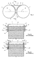
- the prior art casting installation between cylinders shown in the Figures 1 and 2 comprises, conventionally, two cylinders 1, 1 'close to horizontal axes whose cylindrical side walls 2, 2 'are energetically cooled internally. They are rotated in opposite directions by known means not shown.
- the space of casting, in which the liquid steel 3 is introduced by a nozzle (not shown) connected to a container such as a pocket or a distributor, is delimited by the side walls 2, 2 ' cylinders 1, 1 'and by side faces 4, 4' made of refractory material (the side face 4 ' is not shown in Figure 1 to make visible the constitution of the side face 4).
- the elements made of refractory material of the faces side 4, 4 'of the example shown have two parts. Their portions 8, 9 which are in contact with the edges 5, 5 'of the cylinders 1, 1' or in the vicinity of the zones where this contact, as well as all of their lower part 10 over a height of approximately 150 mm, are made of a first material, of high hardness and having great qualities of resistance to corrosion by liquid metal.
- the central part 11 remaining of the faces side 4, 4 ' is made of a material preferably having good properties thermal insulation and may be of a lower hardness than said first material.
- FIG 2a shows the installation at the very start of casting, while the side faces 4, 4 ' are new and have facing the edges 5, 5 'of the cylinders, the liquid steel 3 and the strip 7 a uniformly flat front face.
- Figure 2b shows the same installation at a later stage of casting, while the side faces 4, 4 'have already undergone a significant wear.
- the central part 11 has been consumed at a depth "e” relatively significant by corrosion and mechanical wear in contact with liquid steel 3 in movement.
- the hard material portions 8, 9 and 10 were worn by friction on a depth "x" in their zones which face the edges 5, 5 'of the cylinders 1, 1', while their zones not subjected to the friction of the edges 5, 5 ′ have, in the ideal case shown, no wear.
- this positive insert 12 is subjected on its front part to intense stresses on the part of the steel 3 which may be, in its vicinity, already in a state partially solidified. Its lateral parts are likewise subject to contact with the skins. of solidified metal against the cylinders. Consequently, under the effect of these various stresses, there is a periodic and uncontrolled rupture of the lower part of the positive insert 12, along a generally irregular line 13.
- this rupture extends relatively deep into the refractory, to the point of destroying sealing the casting space and leaving the possibility for liquid steel 14 to escape out of this space by a crevice 15. This is, in particular, the case if the rupture propagates upwards from positive insert 12, therefore towards regions where the metal which borders the lateral face 4, 4 ′ is entirely in the liquid state. If this steel 14 gets immediately solidifies between the side face 4 and the edge 5, it causes the face to recede lateral 4 and contributes a little more to its deterioration, as well as to that of edge 5. If the breach 15 opens to the outside, the liquid steel 14 can flow out of the machine casting with all the risks that this entails for the installation and the personnel.
- the longitudinal sections in depth of the recess 16 and of the refractory 17 which fills it have the shape of a rectangular trapezoid whose point is oriented towards the part upper part of the pouring space, and the large base of which is situated opposite this same casting space.
- This large base extends over a height "h 1 " above the level of the neck 6, "h 1 " being equal to, for example, 70 mm (this value does not include the part of the small face intended for extend under the neck 6 after its installation).
- the small base of the trapezoid, located at the rear of the recess extends over a height "h 2 " above the level of the neck 6, equal, for example, to 55 mm.
- the recess 16 has a maximum depth "p" equal to, for example, 15 mm. "p" must be greater than the maximum tolerated value of the wear of the parts 8, 9, 10 of hard material of the lateral face 4, 4 ′, so that the refractory 17 which fills it can play its role during the assembly of casting.
- Figure 4 shows in operation a casting installation between cylinders equipped with side faces 4, 4 'according to the invention, under the same conditions as the installation shown in Figure 2b.
- a positive insert 12 of maximum thickness "x" at the levels where the side faces 4, 4 'are formed by the hard refractory 10.
- the parts of the side faces 4, 4 'According to the invention which face the strip 7 or areas where the metal 3 is in the partially solidified state undergo wear the quantitative importance of which is a function of the stresses to which they are subjected. These stresses tend to increase with the solid fraction of the metal 3, and consequently, the penetration depth of the positive insert 12 decreases as one approaches the neck 6.
- the positive insert 12 can possibly, as shown in Figure 4, be fully consumed.
- the refractory 17 lining the recess 16 of each lateral face 4, 4 ′ according to the invention does not have a very high hardness, its wear is regular and we do not normally observe the presence of rupture lines of tormented shapes and random as line 13 in Figure 2b.
- this rupture would necessarily stop at the limits of the recess 16.
- the recess 16 has a section longitudinal trapezoidal shape. We therefore aim to ensure that, once the consumption of refractory 17 primed, the hard refractory 10 exposed to the liquid metal 3 or partially solidified a beveled surface offering only a relatively limited grip mechanical wear. A rectangular section for this recess 16 would leave after wear of the refractory 17 a hard refractory 10 having a sharp angle making it more sensitive to wear and more prone to sudden and irregular ruptures. That said, such a section rectangular of the recess 16 would essentially remain within the scope of the invention such that defined by the appended claims.
- the recess 16 has a section longitudinal in the shape of a right triangle.
- the invention can easily be adapted to lateral faces which would have shapes different from the one shown in the previous example.
Landscapes
- Engineering & Computer Science (AREA)
- Mechanical Engineering (AREA)
- Continuous Casting (AREA)
- Electroplating Methods And Accessories (AREA)
- Heat Treatment Of Strip Materials And Filament Materials (AREA)
- Building Environments (AREA)
- Coating With Molten Metal (AREA)
- Braking Arrangements (AREA)
- Forms Removed On Construction Sites Or Auxiliary Members Thereof (AREA)
- Filling Or Discharging Of Gas Storage Vessels (AREA)
- Pipe Accessories (AREA)
Applications Claiming Priority (2)
| Application Number | Priority Date | Filing Date | Title |
|---|---|---|---|
| FR9708447 | 1997-07-04 | ||
| FR9708447A FR2765504B1 (fr) | 1997-07-04 | 1997-07-04 | Face laterale d'obturation de l'espace de coulee d'une installation de coulee continue entre cylindres de bandes minces metalliques |
Publications (2)
| Publication Number | Publication Date |
|---|---|
| EP0894556A1 EP0894556A1 (fr) | 1999-02-03 |
| EP0894556B1 true EP0894556B1 (fr) | 2002-07-17 |
Family
ID=9508828
Family Applications (1)
| Application Number | Title | Priority Date | Filing Date |
|---|---|---|---|
| EP98401491A Expired - Lifetime EP0894556B1 (fr) | 1997-07-04 | 1998-06-18 | Face latérale d'obturation de l'espace de coulée d'une installation de coulée continue entre cylindres de bandes minces métalliques |
Country Status (23)
| Country | Link |
|---|---|
| US (1) | US6082437A (cs) |
| EP (1) | EP0894556B1 (cs) |
| JP (1) | JPH1177253A (cs) |
| KR (1) | KR100537323B1 (cs) |
| CN (1) | CN1074694C (cs) |
| AT (1) | ATE220584T1 (cs) |
| AU (1) | AU740876B2 (cs) |
| BR (1) | BR9802349A (cs) |
| CA (1) | CA2242684A1 (cs) |
| CZ (1) | CZ289390B6 (cs) |
| DE (1) | DE69806549T2 (cs) |
| DK (1) | DK0894556T3 (cs) |
| ES (1) | ES2178126T3 (cs) |
| FR (1) | FR2765504B1 (cs) |
| PL (1) | PL186206B1 (cs) |
| PT (1) | PT894556E (cs) |
| RO (1) | RO118854B1 (cs) |
| RU (1) | RU2201839C2 (cs) |
| SK (1) | SK283481B6 (cs) |
| TR (1) | TR199801294A2 (cs) |
| TW (1) | TW415858B (cs) |
| UA (1) | UA54407C2 (cs) |
| ZA (1) | ZA985801B (cs) |
Families Citing this family (17)
| Publication number | Priority date | Publication date | Assignee | Title |
|---|---|---|---|---|
| IT1284201B1 (it) * | 1996-07-31 | 1998-05-08 | Sviluppo Materiali Spa | Piastre con riporti ceramici antiusura per macchine per colata conntinua di corpi piani sottili e procedimento per la loro |
| AT412195B (de) * | 2002-06-25 | 2004-11-25 | Voest Alpine Ind Anlagen | Verfahren zur erzeugung eines metallbandes mit einer zweiwalzengiesseinrichtung |
| FR2842130B1 (fr) * | 2002-07-12 | 2004-10-15 | Usinor | Face laterale pour installation de coulee continue de bandes metalliques entre deux cylindres |
| CH697156A5 (de) * | 2004-09-17 | 2008-05-30 | Main Man Inspiration Ag | Seitenabdichtung eines zwischen zwei Giessrollen einer Bandgiessmaschine gebildeten Giessspaltes. |
| CN100368120C (zh) * | 2005-12-02 | 2008-02-13 | 重庆大学 | 双辊连铸镁合金薄带浇铸装置 |
| US8042601B2 (en) * | 2006-03-24 | 2011-10-25 | Nucor Corporation | Side dam with insert |
| US7556084B2 (en) * | 2006-03-24 | 2009-07-07 | Nucor Corporation | Long wear side dams |
| JP5012353B2 (ja) * | 2007-09-19 | 2012-08-29 | 株式会社Ihi | 双ロール鋳造機の操業方法及びサイド堰支持装置 |
| US8191610B2 (en) * | 2008-11-24 | 2012-06-05 | Nucor Corporation | Strip casting apparatus with improved side dam |
| US7888158B1 (en) * | 2009-07-21 | 2011-02-15 | Sears Jr James B | System and method for making a photovoltaic unit |
| CN102266930B (zh) * | 2011-04-26 | 2012-06-13 | 江苏标新久保田工业有限公司 | 密封钢液的挡板装置与制作方法及应用该挡板装置的模具 |
| JP5837758B2 (ja) | 2011-04-27 | 2015-12-24 | キャストリップ・リミテッド・ライアビリティ・カンパニー | 双ロール鋳造装置及びその制御方法 |
| KR101482350B1 (ko) * | 2012-12-27 | 2015-01-13 | 주식회사 포스코 | 쌍롤식 박판 주조장치 |
| US9533347B2 (en) * | 2013-11-14 | 2017-01-03 | Posco | Casting roll for twin-roll strip caster |
| US10046384B2 (en) | 2015-09-30 | 2018-08-14 | Nucor Corporation | Side dam with pocket |
| CN106541092B (zh) * | 2016-11-25 | 2018-03-27 | 江西理工大学 | 一种双辊薄带连铸用侧封板及其使用方法 |
| RU2726543C1 (ru) * | 2016-12-26 | 2020-07-14 | Баошань Айрон Энд Стил Ко., Лтд. | Удерживающее устройство боковой перегородки для непрерывного литья тонкой полосы с двумя валками и способ его установки |
Family Cites Families (17)
| Publication number | Priority date | Publication date | Assignee | Title |
|---|---|---|---|---|
| JPS60148646A (ja) * | 1984-01-11 | 1985-08-05 | Mitsubishi Heavy Ind Ltd | ツインドラム方式の薄板連続鋳造装置 |
| JPS60162558A (ja) * | 1984-02-03 | 1985-08-24 | Mitsubishi Heavy Ind Ltd | 薄板連続鋳造装置 |
| JPS62212041A (ja) * | 1986-03-11 | 1987-09-18 | Kawasaki Steel Corp | 薄鋳片連続鋳造用短辺鋳型 |
| JPS635855A (ja) * | 1986-06-25 | 1988-01-11 | Kawasaki Steel Corp | 薄鋳片連続鋳造用短辺鋳型 |
| JPH07102426B2 (ja) * | 1988-06-20 | 1995-11-08 | 株式会社日立製作所 | 双ロール式連続鋳造装置 |
| EP0348227B1 (en) * | 1988-06-24 | 1993-05-05 | Kawasaki Steel Corporation | Side wall construction for continuous belt caster |
| SU1639882A1 (ru) * | 1988-10-05 | 1991-04-07 | Институт черной металлургии | Машина непрерывного лить тонких сл бов |
| FR2652021A1 (fr) * | 1989-06-15 | 1991-03-22 | Siderurgie Fse Inst Rech | Paroi d'obturation laterale pour une installation de coulee continue entre parois mobiles. |
| FR2655577B1 (fr) * | 1989-12-07 | 1992-01-24 | Siderurgie Fse Inst Rech | Installation de coulee continue de produits metalliques minces entre deux cylindres. |
| JPH0741376B2 (ja) * | 1990-06-11 | 1995-05-10 | 新日本製鐵株式会社 | 薄帯連続鋳造方法 |
| FR2666256B1 (fr) * | 1990-09-03 | 1992-10-16 | Usinor Sacilor | Installation de coulee continue entre cylindres. |
| FR2671991A1 (fr) * | 1991-01-25 | 1992-07-31 | Usinor Sacilor | Materiau refractaire pour petite face d'une installation de coulee continue des metaux entre cyclindres, et petite face ainsi realisee. |
| RU2041768C1 (ru) * | 1991-12-11 | 1995-08-20 | Юзинор Сасилор С.А. | Установка для непрерывной разливки |
| FR2686278A1 (fr) * | 1992-01-17 | 1993-07-23 | Usinor Sacilor | Dispositif de coulee continue entre cylindres comportant des parois laterales en materiaux refractaires. |
| JPH0749140B2 (ja) * | 1992-02-17 | 1995-05-31 | 三菱重工業株式会社 | 双ドラム式連続鋳造装置 |
| FR2721843B1 (fr) * | 1994-06-30 | 1996-08-30 | Unisor Sacilor | Disposition de coulee continue entre cylindres a parois d'obturation laterale appliquees |
| JPH09155509A (ja) * | 1995-12-01 | 1997-06-17 | Toshiba Ceramics Co Ltd | ツインロール式ストリップキャスト用サイドダム |
-
1997
- 1997-07-04 FR FR9708447A patent/FR2765504B1/fr not_active Expired - Fee Related
-
1998
- 1998-06-18 ES ES98401491T patent/ES2178126T3/es not_active Expired - Lifetime
- 1998-06-18 PT PT98401491T patent/PT894556E/pt unknown
- 1998-06-18 DK DK98401491T patent/DK0894556T3/da active
- 1998-06-18 EP EP98401491A patent/EP0894556B1/fr not_active Expired - Lifetime
- 1998-06-18 AT AT98401491T patent/ATE220584T1/de not_active IP Right Cessation
- 1998-06-18 DE DE69806549T patent/DE69806549T2/de not_active Expired - Fee Related
- 1998-06-23 AU AU73105/98A patent/AU740876B2/en not_active Ceased
- 1998-06-26 US US09/104,981 patent/US6082437A/en not_active Expired - Fee Related
- 1998-06-26 TW TW087110344A patent/TW415858B/zh not_active IP Right Cessation
- 1998-06-30 UA UA98063412A patent/UA54407C2/uk unknown
- 1998-07-01 SK SK907-98A patent/SK283481B6/sk unknown
- 1998-07-02 BR BR9802349-7A patent/BR9802349A/pt not_active IP Right Cessation
- 1998-07-02 CZ CZ19982109A patent/CZ289390B6/cs not_active IP Right Cessation
- 1998-07-02 ZA ZA985801A patent/ZA985801B/xx unknown
- 1998-07-03 CN CN98115667A patent/CN1074694C/zh not_active Expired - Fee Related
- 1998-07-03 RU RU98113401/02A patent/RU2201839C2/ru not_active IP Right Cessation
- 1998-07-03 RO RO98-01144A patent/RO118854B1/ro unknown
- 1998-07-03 TR TR1998/01294A patent/TR199801294A2/xx unknown
- 1998-07-03 PL PL98327222A patent/PL186206B1/pl not_active IP Right Cessation
- 1998-07-03 CA CA002242684A patent/CA2242684A1/fr not_active Abandoned
- 1998-07-03 KR KR1019980026814A patent/KR100537323B1/ko not_active Expired - Fee Related
- 1998-07-06 JP JP10190170A patent/JPH1177253A/ja not_active Withdrawn
Also Published As
| Publication number | Publication date |
|---|---|
| PL186206B1 (pl) | 2003-11-28 |
| SK90798A3 (en) | 1999-01-11 |
| CZ210998A3 (cs) | 1999-01-13 |
| CN1074694C (zh) | 2001-11-14 |
| CZ289390B6 (cs) | 2002-01-16 |
| PL327222A1 (en) | 1999-01-18 |
| DK0894556T3 (da) | 2002-10-28 |
| ATE220584T1 (de) | 2002-08-15 |
| EP0894556A1 (fr) | 1999-02-03 |
| FR2765504B1 (fr) | 1999-08-20 |
| CA2242684A1 (fr) | 1999-01-04 |
| TR199801294A3 (tr) | 1999-10-21 |
| TR199801294A2 (xx) | 1999-10-21 |
| DE69806549D1 (de) | 2002-08-22 |
| SK283481B6 (sk) | 2003-08-05 |
| RO118854B1 (ro) | 2003-12-30 |
| AU740876B2 (en) | 2001-11-15 |
| AU7310598A (en) | 1999-01-14 |
| PT894556E (pt) | 2002-10-31 |
| KR19990013592A (ko) | 1999-02-25 |
| RU2201839C2 (ru) | 2003-04-10 |
| DE69806549T2 (de) | 2003-01-16 |
| BR9802349A (pt) | 1999-10-13 |
| KR100537323B1 (ko) | 2006-03-09 |
| ES2178126T3 (es) | 2002-12-16 |
| US6082437A (en) | 2000-07-04 |
| JPH1177253A (ja) | 1999-03-23 |
| ZA985801B (en) | 1999-01-14 |
| FR2765504A1 (fr) | 1999-01-08 |
| CN1210769A (zh) | 1999-03-17 |
| TW415858B (en) | 2000-12-21 |
| UA54407C2 (uk) | 2003-03-17 |
Similar Documents
| Publication | Publication Date | Title |
|---|---|---|
| EP0894556B1 (fr) | Face latérale d'obturation de l'espace de coulée d'une installation de coulée continue entre cylindres de bandes minces métalliques | |
| EP1038612A1 (fr) | Procédé de fabrication de bandes en acier au carbone par coulée continue entre deux cylindres | |
| EP0759335B1 (fr) | Dispositif de soutien d'une face latérale d'une installation de coulée continue de bandes métalliques entre cylindres | |
| EP0432073A1 (fr) | Installation de coulée continue de produits métalliques minces entre deux cylindres | |
| EP0767714B1 (fr) | Face laterale pour une machine de coulee en continu de tole mince | |
| EP0477045B1 (fr) | Installation de coulée continue entre cylindres | |
| EP0901851B1 (fr) | Face laterale pour l'obturation de l'espace de coulee d'une installation de coulee continue de bandes metalliques entre cylindres, et installation de coulee ainsi equipee | |
| WO2004007116A2 (fr) | Face laterale pour installation de coulee continue de bandes metalliques entre deux cylindres | |
| EP0622138A1 (fr) | Procédé et dispositif d'élaboration d'au moins une bande métallique de faible largeur et bande métallique obtenue par ce procédé | |
| EP0875315B1 (fr) | Installation de coulée continue de bandes métalliques entre deux cylindres | |
| EP0435729A1 (fr) | Dispositif de coulée continue de produits métalliques minces entre deux cylindres refroidis en rotation | |
| EP0709151B1 (fr) | Surface de coulée d'une lingotière de coulée continue des métaux à paroi mobile | |
| EP0413650A1 (fr) | Procédé et dispositif de coulée continue directe de produits métalliques minces | |
| EP1144142B1 (fr) | Face laterale pour installation de coulee continue de bandes metalliques | |
| LU88041A1 (fr) | Procede pour la coulee en continu de pieces metalliques extrudees | |
| EP0552125A1 (fr) | Dispositif de coulée continue entre cylindres comportant des parois latérales en matériaux réfractaires | |
| WO2000025958A1 (fr) | Face laterale pour installation de coulee continue de bandes metalliques entre deux cylindres | |
| FR2723013A1 (fr) | Face laterale pour une machine de coulee en continu de tole mince | |
| EP1007247A1 (fr) | Procede et dispositif pour la coulee continue en charge des metaux | |
| LU87784A1 (fr) | Panneau de refroidissement pour four a cuve | |
| WO1997014519A1 (fr) | Installation de coulee continue de filaments metalliques directement a partir de metal liquide | |
| BE655583A (cs) |
Legal Events
| Date | Code | Title | Description |
|---|---|---|---|
| PUAI | Public reference made under article 153(3) epc to a published international application that has entered the european phase |
Free format text: ORIGINAL CODE: 0009012 |
|
| AK | Designated contracting states |
Kind code of ref document: A1 Designated state(s): AT BE CH CY DE DK ES FI FR GB GR IE IT LI LU NL PT SE |
|
| AX | Request for extension of the european patent |
Free format text: AL;LT;LV;MK;RO;SI |
|
| 17P | Request for examination filed |
Effective date: 19990803 |
|
| AKX | Designation fees paid |
Free format text: AT BE CH CY DE DK ES FI FR GB GR IE IT LI LU NL PT SE |
|
| GRAG | Despatch of communication of intention to grant |
Free format text: ORIGINAL CODE: EPIDOS AGRA |
|
| 17Q | First examination report despatched |
Effective date: 20010928 |
|
| GRAG | Despatch of communication of intention to grant |
Free format text: ORIGINAL CODE: EPIDOS AGRA |
|
| GRAH | Despatch of communication of intention to grant a patent |
Free format text: ORIGINAL CODE: EPIDOS IGRA |
|
| GRAH | Despatch of communication of intention to grant a patent |
Free format text: ORIGINAL CODE: EPIDOS IGRA |
|
| GRAA | (expected) grant |
Free format text: ORIGINAL CODE: 0009210 |
|
| AK | Designated contracting states |
Kind code of ref document: B1 Designated state(s): AT BE CH CY DE DK ES FI FR GB GR IE IT LI LU NL PT SE |
|
| REF | Corresponds to: |
Ref document number: 220584 Country of ref document: AT Date of ref document: 20020815 Kind code of ref document: T |
|
| REG | Reference to a national code |
Ref country code: GB Ref legal event code: FG4D Free format text: NOT ENGLISH |
|
| REG | Reference to a national code |
Ref country code: CH Ref legal event code: EP |
|
| REG | Reference to a national code |
Ref country code: IE Ref legal event code: FG4D Free format text: FRENCH |
|
| REF | Corresponds to: |
Ref document number: 69806549 Country of ref document: DE Date of ref document: 20020822 |
|
| GBT | Gb: translation of ep patent filed (gb section 77(6)(a)/1977) |
Effective date: 20020919 |
|
| REG | Reference to a national code |
Ref country code: DK Ref legal event code: T3 |
|
| REG | Reference to a national code |
Ref country code: PT Ref legal event code: SC4A Free format text: AVAILABILITY OF NATIONAL TRANSLATION Effective date: 20020809 |
|
| REG | Reference to a national code |
Ref country code: GR Ref legal event code: EP Ref document number: 20020403443 Country of ref document: GR |
|
| REG | Reference to a national code |
Ref country code: ES Ref legal event code: FG2A Ref document number: 2178126 Country of ref document: ES Kind code of ref document: T3 |
|
| PLBE | No opposition filed within time limit |
Free format text: ORIGINAL CODE: 0009261 |
|
| STAA | Information on the status of an ep patent application or granted ep patent |
Free format text: STATUS: NO OPPOSITION FILED WITHIN TIME LIMIT |
|
| PG25 | Lapsed in a contracting state [announced via postgrant information from national office to epo] |
Ref country code: CY Free format text: LAPSE BECAUSE OF FAILURE TO SUBMIT A TRANSLATION OF THE DESCRIPTION OR TO PAY THE FEE WITHIN THE PRESCRIBED TIME-LIMIT Effective date: 20030618 |
|
| 26N | No opposition filed |
Effective date: 20030422 |
|
| PGFP | Annual fee paid to national office [announced via postgrant information from national office to epo] |
Ref country code: IE Payment date: 20040520 Year of fee payment: 7 Ref country code: PT Payment date: 20040520 Year of fee payment: 7 |
|
| PGFP | Annual fee paid to national office [announced via postgrant information from national office to epo] |
Ref country code: GR Payment date: 20040526 Year of fee payment: 7 |
|
| PGFP | Annual fee paid to national office [announced via postgrant information from national office to epo] |
Ref country code: FI Payment date: 20040602 Year of fee payment: 7 Ref country code: CH Payment date: 20040602 Year of fee payment: 7 |
|
| PGFP | Annual fee paid to national office [announced via postgrant information from national office to epo] |
Ref country code: DK Payment date: 20040604 Year of fee payment: 7 |
|
| PGFP | Annual fee paid to national office [announced via postgrant information from national office to epo] |
Ref country code: ES Payment date: 20040615 Year of fee payment: 7 |
|
| PG25 | Lapsed in a contracting state [announced via postgrant information from national office to epo] |
Ref country code: FI Free format text: LAPSE BECAUSE OF NON-PAYMENT OF DUE FEES Effective date: 20050614 |
|
| PG25 | Lapsed in a contracting state [announced via postgrant information from national office to epo] |
Ref country code: IE Free format text: LAPSE BECAUSE OF NON-PAYMENT OF DUE FEES Effective date: 20050620 Ref country code: ES Free format text: LAPSE BECAUSE OF NON-PAYMENT OF DUE FEES Effective date: 20050620 |
|
| PG25 | Lapsed in a contracting state [announced via postgrant information from national office to epo] |
Ref country code: LI Free format text: LAPSE BECAUSE OF NON-PAYMENT OF DUE FEES Effective date: 20050630 Ref country code: DK Free format text: LAPSE BECAUSE OF NON-PAYMENT OF DUE FEES Effective date: 20050630 Ref country code: CH Free format text: LAPSE BECAUSE OF NON-PAYMENT OF DUE FEES Effective date: 20050630 |
|
| PG25 | Lapsed in a contracting state [announced via postgrant information from national office to epo] |
Ref country code: PT Free format text: LAPSE BECAUSE OF NON-PAYMENT OF DUE FEES Effective date: 20051219 |
|
| PG25 | Lapsed in a contracting state [announced via postgrant information from national office to epo] |
Ref country code: GR Free format text: LAPSE BECAUSE OF NON-PAYMENT OF DUE FEES Effective date: 20060103 |
|
| REG | Reference to a national code |
Ref country code: CH Ref legal event code: PL |
|
| REG | Reference to a national code |
Ref country code: DK Ref legal event code: EBP |
|
| REG | Reference to a national code |
Ref country code: IE Ref legal event code: MM4A |
|
| REG | Reference to a national code |
Ref country code: ES Ref legal event code: FD2A Effective date: 20050620 |
|
| PGFP | Annual fee paid to national office [announced via postgrant information from national office to epo] |
Ref country code: NL Payment date: 20090603 Year of fee payment: 12 |
|
| PGFP | Annual fee paid to national office [announced via postgrant information from national office to epo] |
Ref country code: SE Payment date: 20090605 Year of fee payment: 12 Ref country code: IT Payment date: 20090620 Year of fee payment: 12 Ref country code: AT Payment date: 20090615 Year of fee payment: 12 |
|
| PGFP | Annual fee paid to national office [announced via postgrant information from national office to epo] |
Ref country code: BE Payment date: 20090619 Year of fee payment: 12 |
|
| PGFP | Annual fee paid to national office [announced via postgrant information from national office to epo] |
Ref country code: LU Payment date: 20090720 Year of fee payment: 12 Ref country code: GB Payment date: 20090617 Year of fee payment: 12 Ref country code: DE Payment date: 20090615 Year of fee payment: 12 |
|
| BERE | Be: lapsed |
Owner name: *HYSSEN STAHL A.G. Effective date: 20100630 Owner name: *USINOR Effective date: 20100630 |
|
| REG | Reference to a national code |
Ref country code: NL Ref legal event code: V1 Effective date: 20110101 |
|
| EUG | Se: european patent has lapsed | ||
| GBPC | Gb: european patent ceased through non-payment of renewal fee |
Effective date: 20100618 |
|
| REG | Reference to a national code |
Ref country code: FR Ref legal event code: ST Effective date: 20110228 |
|
| PG25 | Lapsed in a contracting state [announced via postgrant information from national office to epo] |
Ref country code: IT Free format text: LAPSE BECAUSE OF NON-PAYMENT OF DUE FEES Effective date: 20100618 |
|
| PG25 | Lapsed in a contracting state [announced via postgrant information from national office to epo] |
Ref country code: DE Free format text: LAPSE BECAUSE OF NON-PAYMENT OF DUE FEES Effective date: 20110101 |
|
| PG25 | Lapsed in a contracting state [announced via postgrant information from national office to epo] |
Ref country code: FR Free format text: LAPSE BECAUSE OF NON-PAYMENT OF DUE FEES Effective date: 20100630 Ref country code: AT Free format text: LAPSE BECAUSE OF NON-PAYMENT OF DUE FEES Effective date: 20100618 Ref country code: NL Free format text: LAPSE BECAUSE OF NON-PAYMENT OF DUE FEES Effective date: 20110101 |
|
| PG25 | Lapsed in a contracting state [announced via postgrant information from national office to epo] |
Ref country code: BE Free format text: LAPSE BECAUSE OF NON-PAYMENT OF DUE FEES Effective date: 20100630 |
|
| PG25 | Lapsed in a contracting state [announced via postgrant information from national office to epo] |
Ref country code: GB Free format text: LAPSE BECAUSE OF NON-PAYMENT OF DUE FEES Effective date: 20100618 |
|
| PG25 | Lapsed in a contracting state [announced via postgrant information from national office to epo] |
Ref country code: LU Free format text: LAPSE BECAUSE OF NON-PAYMENT OF DUE FEES Effective date: 20100618 Ref country code: SE Free format text: LAPSE BECAUSE OF NON-PAYMENT OF DUE FEES Effective date: 20100619 |
|
| PGFP | Annual fee paid to national office [announced via postgrant information from national office to epo] |
Ref country code: FR Payment date: 20090611 Year of fee payment: 12 |