EP0900711B1 - Elektrische Servolenkung - Google Patents
Elektrische Servolenkung Download PDFInfo
- Publication number
- EP0900711B1 EP0900711B1 EP98116491A EP98116491A EP0900711B1 EP 0900711 B1 EP0900711 B1 EP 0900711B1 EP 98116491 A EP98116491 A EP 98116491A EP 98116491 A EP98116491 A EP 98116491A EP 0900711 B1 EP0900711 B1 EP 0900711B1
- Authority
- EP
- European Patent Office
- Prior art keywords
- torque sensor
- value
- output
- detecting
- cumulating
- Prior art date
- Legal status (The legal status is an assumption and is not a legal conclusion. Google has not performed a legal analysis and makes no representation as to the accuracy of the status listed.)
- Expired - Lifetime
Links
- 238000001514 detection method Methods 0.000 claims description 124
- 230000007935 neutral effect Effects 0.000 claims description 46
- 230000001955 cumulated effect Effects 0.000 claims description 44
- 238000006073 displacement reaction Methods 0.000 claims description 25
- 238000005070 sampling Methods 0.000 claims 1
- 230000007257 malfunction Effects 0.000 description 66
- 230000001186 cumulative effect Effects 0.000 description 28
- 238000005259 measurement Methods 0.000 description 15
- 238000010586 diagram Methods 0.000 description 10
- 238000000034 method Methods 0.000 description 2
- 238000012544 monitoring process Methods 0.000 description 1
Images






Classifications
-
- B—PERFORMING OPERATIONS; TRANSPORTING
- B62—LAND VEHICLES FOR TRAVELLING OTHERWISE THAN ON RAILS
- B62D—MOTOR VEHICLES; TRAILERS
- B62D6/00—Arrangements for automatically controlling steering depending on driving conditions sensed and responded to, e.g. control circuits
- B62D6/08—Arrangements for automatically controlling steering depending on driving conditions sensed and responded to, e.g. control circuits responsive only to driver input torque
- B62D6/10—Arrangements for automatically controlling steering depending on driving conditions sensed and responded to, e.g. control circuits responsive only to driver input torque characterised by means for sensing or determining torque
-
- B—PERFORMING OPERATIONS; TRANSPORTING
- B62—LAND VEHICLES FOR TRAVELLING OTHERWISE THAN ON RAILS
- B62D—MOTOR VEHICLES; TRAILERS
- B62D5/00—Power-assisted or power-driven steering
- B62D5/04—Power-assisted or power-driven steering electrical, e.g. using an electric servo-motor connected to, or forming part of, the steering gear
- B62D5/0457—Power-assisted or power-driven steering electrical, e.g. using an electric servo-motor connected to, or forming part of, the steering gear characterised by control features of the drive means as such
- B62D5/0481—Power-assisted or power-driven steering electrical, e.g. using an electric servo-motor connected to, or forming part of, the steering gear characterised by control features of the drive means as such monitoring the steering system, e.g. failures
- B62D5/049—Power-assisted or power-driven steering electrical, e.g. using an electric servo-motor connected to, or forming part of, the steering gear characterised by control features of the drive means as such monitoring the steering system, e.g. failures detecting sensor failures
Definitions
- the present invention relates to improvement of an electric power steering apparatus for steering assistance based on an output of a torque sensor which detects a steering torque. More particularly, the invention relates to detection of malfunction for the torque sensor.
- FIG. 1 is a block diagram showing the constitution of an essential part of the conventional electric power steering apparatus.
- a steering torque signal from a torque sensor 2 provided on a steering shaft (not illustrated) is phase compensated by a phase compensation unit 11 and given to an assist control unit 12.
- a vehicle speed signal from a vehicle speed sensor 7 is given to the assist control unit 12.
- the assist control unit 12 outputs a target current value for assist control (steering assist control) based on the steering torque signal from the phase compensation unit 11 and the vehicle speed signal from the vehicle speed sensor 7 and gives the value to subtracting means 15.
- the subtracting means 15 obtains a deviation between the target current value from the assist control unit 12 and a feed back value of the drive current of the motor 5 detected by the motor current detection circuit 6, and gives this deviation to the motor drive circuit 16.
- the motor drive circuit 16 determines a motor current based on the deviation and gives it to the motor 5 to drive it in rotation.
- the neutral point in order to the measurement may shift.
- the displacement by the shift is relatively small, there is a problem that the displacement cannot be detected and the apparatus is doing nothing about the condition that the torque sensor 2 has large measuring errors.
- the present invention has been made to settle the problematic points as described above.
- the object of the present invention is to provide an electric power steering apparatus with which even a small displacement of a neutral point in order to a measurement of a torque sensor can be detected.
- the electric power steering apparatus of the present invention for assisting steering based on an output of a torque sensor which detects a steering torque, comprises: cumulating means for cumulating the output for a predetermined period of time; comparing means for comparing an absolute value of the result cumulated by the cumulating means with a predetermined value; and means for detecting a displacement of a detection neutral point of the torque sensor based on the results of comparison by the comparing means.
- the cumulating means cumulates the output of the torque sensor for the predetermined period of time.
- the comparing means compares an absolute value of the cumulated value with the predetermined value, and the means for detecting detects the displacement of the neutral point in order to a measurement of a torque sensor based on the results of comparison.
- the cumulated output value of the torque sensor should indicate approximately “0” for a long operating time period. Therefore, if the cumulated value is deviated by more than the predetermined value from "0", then it can be judged that the torque sensor has been failed. Because of this, in case the preset value of the neutral point is "0", even a small displacement of a neutral point in order to a measurement of a torque sensor can be detected.
- An electric power steering apparatus according to a prefered embodiment of the present invention is defined by claim 2.
- the output of the torque sensor is periodically sampled and the sampled outputs are cumulated for the predetermined period of time.
- the counting means counts the number of times cumulated
- the calculating means calculates the average output value of the torque sensor based on the cumulated result and the number of times counted. Further, the means for calculating the difference calculates the difference between the expected output value of the torque sensor at its neutral point and the above average output value. Comparing means compares an absolute value of the calculated difference with the predetermined value, and means for detecting the displacement based on the results of the comparison.
- the average output value of the torque sensor should show approximately as that at its neutral point for a long operating time period. Therefore, if the average output value for a long predetermined time is deviated by higher than the predetermined value from the neutral point, then it can be judged that the torque sensor has been failed. Because of this, in case that the preset value of the neutral point is not "0", even a small displacement of a neutral point in order to a measurement of a torque sensor can be detected.
- a still further embodiment of the electric power steering apparatus of the invention further comprises: a vehicle speed sensor for detecting a vehicle speed; and steering angle detecting means for detecting a steering angle, wherein the cumulating means cumulates when the vehicle speed detected by the vehicle speed sensor is higher than a predetermined vehicle speed and the steering angle detected by the steering angle detecting means is within a predetermined range.
- the cumulating means cumulates the outputs of the torque sensor when the vehicle speed detected by the vehicle speed sensor is higher than the predetermined vehicle speed and the steering angle detected by the steering angle detecting means is within the predetermined range. Therefore, a small output value of the torque sensor in a condition where the vehicle runs approximately straight becomes the subject of processing, and the detection precision of a small displacement of the neutral point in order to a measurement of the torque sensor can be improved.
- Another embodiment of the electric power steering apparatus of the present invention further comprises: steering angular velocity detecting means for detecting a steering angular velocity, wherein the cumulating means cumulates when the steering angular velocity detected by the steering angular velocity detecting means is lower than a predetermined steering angular velocity.
- the cumulating means cumulates the outputs of the torque sensor when the steering angular velocity detected by the steering angular velocity detecting means is lower than the predetermined steering angular velocity. Therefore, a small output value of the torque sensor in a condition where the vehicle runs approximately straight becomes the subject of processing, and the detection precision of a small displacement of the neutral point in order to a measurement of the torque sensor can be improved.
- Another embodiment of the electric power steering apparatus of the present invention for assisting steering based on an output of a torque sensor which detects a steering torque, is defined by claim 5.
- the means for detecting detects the "ON" operation of the ignition key, and the cumulating means cumulates the outputs of the torque sensor at each time of detecting for a predetermined number of times.
- the comparing means compares an absolute value of the cumulated value with the predetermined value, and the means for detecting detects the displacement of the detection neutral point of the torque sensor based on the results of the comparison.
- a driver may often keep his/her hands off from the steering wheel while he/she is turning the ignition key to "ON".
- the preset neutral point of the torque sensor is "0"
- the means for detecting detects the "ON" operation of the ignition key
- a small torque sensor output becomes the subject of processing, and the detection precision of a small displacement of the neutral point measured by the torque sensor can be improved.
- Another embodiment of the electric power steering apparatus of the present invention for assisting steering based on an output of a torque sensor which detects a steering torque, is defined by claim 6.
- the means for detecting detects the "ON" operation of the ignition key
- the cumulating means cumulates the outputs of the torque sensor when detecting the "ON" operation for a predetermined number of times.
- the calculating means calculates the average value of the outputs based on the cumulated value
- the means for calculating the difference calculates the difference between the neutral point to be output by the torque sensor at its neutral point and the average value.
- the comparing means compares the value of the calculated difference with the predetermined value, and the means for detecting detects the displacement of the neutral point in order to a measurement of the torque sensor based on the results of the comparison.
- a driver may often keep his/her hands off from the steering wheel while he/she is turning the ignition key to "ON".
- a preset neutral point of the torque sensor is not "0"
- the means for detecting detects the "ON" operation of the ignition key and obtaining the average value
- a small torque sensor output becomes the subject of processing, and the detection precision of a small displacement of the neutral point in order to a measurement of the torque sensor can be improved.
- Another embodiment of the electric power steering apparatus of the present invention for assisting steering based on an output of a torque sensor which detects a steering torque, is defined by claim 7.
- the detecting means detects the "OFF" operation of the ignition key, and the cumulating means cumulates the output of the torque sensor when detecting for the predetermined number of times.
- the comparing means compares an absolute value of the cumulated value with the predetermined value, and the means for detecting detects the displacement of the neutral point in order to a measurement of the torque sensor based on the results of the comparison.
- a driver may often keep his/her hands off from the steering wheel while he/she is turning the ignition key to "OFF".
- a preset neutral point of the torque sensor is "0"
- the means for detecting detects the "OFF" operation of the ignition key
- a small torque sensor output becomes the subject of processing, and the detection precision of a small displacement of the neutral point in order to a measurement of the torque sensor can be improved.
- Another electric power steering apparatus of the present invention for assisting steering based on an output of a torque sensor which detects a steering torque, is defined by claim 8.
- the means for detecting detects the "OFF" operation of the ignition key, and the cumulating means cumulates the output of the torque sensor when detecting the "OFF" operation for the predetermined number of times.
- the calculating means calculates the average value of the torque sensor outputs based on the cumulated values, and the means for calculating the difference calculates the difference between the value to be output by the torque sensor at the neutral point and the average value.
- the comparing means compares the absolute value of the difference with a predetermined value, and the means for detecting detects the displacement of the neutral point in order to a measurement of the torque sensor based on the results of the comparison.
- a driver may often keep his/her hands off from the steering wheel while he/she is turning the ignition key to "OFF".
- a preset neutral point of the torque sensor is not "0"
- the means for detecting detects the "OFF" operation of the ignition key and obtaining the average value
- a small torque sensor output becomes the subject of processing, and the detection precision of a small displacement of the neutral point in order to a measurement of the torque sensor can be improved.
- a still further embodiment of the electric power steering apparatus of the present invention further comprises: means for judging whether or not the output of the torque sensor is within a predetermined range, wherein the cumulating means cumulates when the output is judged to be within the predetermined range by the means for judging.
- the cumulating means cumulates when the means for judging judges that the output of the torque sensor is within the predetermined range.
- the means for judging judges that the output of the torque sensor is within the predetermined range.
- a still further embodiment of electric power steering apparatus of the present invention for assisting steering based on an output of a torque sensor which includes a mechanical stopper for preventing breakage by over-steering and which detects a steering torque, is defined by claim 10.
- the stopper detecting means detects that the torque sensor reaches to the mechanical stopper.
- the memory means memorizes the torque sensor. output when detected.
- the means for calculating calculates the difference between the output of the torque sensor when detected the reach of the torque sensor to the mechanical stopper and the output memorized in the memory means, the comparing means compares the absolute value of the difference calculated by the means for calculating with the predetermined value; and the means for detecting detects the displacement of the neutral point in order to a measurement of the torque sensor based on the results of the comparison.
- the output of the torque sensor when it reaches to the mechanical stopper is considered as approximately the same (consistent). According to this, by monitoring the deviation, and when the deviation is found to be higher than the predetermined value, it can be judged that the torque sensor has been failed. By this method, even a small displacement of the neutral point in order to a measurement of the torque sensor can be detected.
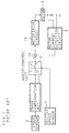
- FIG. 2 is a block diagram showing the constitution of an essential part of the electric power steering apparatus according to Embodiment 1 of the present invention.
- a steering torque signal as an output of a torque sensor 2 provided on a steering shaft (not illustrated) is periodically sampled.
- the sampled steering torque signal is phase compensated by a phase compensation unit 11 and given to an assist control unit 12.
- a vehicle speed signal from a vehicle speed sensor 7 is given to the assist control unit 12, a steering angle middle point calculation unit 20, and a torque sensor malfunction detection unit 8.
- the assist control unit 12 outputs a target current value for assist control (steering assist control) based on the steering torque signal from the phase compensation unit 11 and the vehicle speed signal from the vehicle speed sensor 7.
- the steering torque signal which is an output of the torque sensor 2 is also given to the torque sensor malfunction detection unit 8.
- a motor rotational speed signal from a motor rotary sensor 18 which detects a rotational speed of a motor 5 for steering force assistance is given to a relative steering angle detection unit 19.
- the relative steering angle detection unit 19 detects a relative steering angle of a steering wheel based on the motor rotational signal and gives it to the steering middle point calculation unit 20 and a subtracting means 21.
- the steering middle point calculation unit 20 calculates a steering middle point of the steering wheel when the vehicle straight based on the given relative steering angle and gives the calculation results thereof to the subtracting means 21.
- the subtracting means 21 subtracts the given calculation results based on the relative steering angle to obtain the absolute steering angle which is a steering angle from the steering angle middle point, then gives the signal to the torque sensor malfunction detection unit 8.
- the relative steering angle may be detected by detecting the rotational speed of a steering shaft connected to the steering wheel by using a rotary encoder.
- the absolute steering angle may be directly detected.
- a subtracting means 15 obtains the deviation between the target current value from the assist control unit 12 and the feed back value of the drive current of the motor 5 detected by a motor current detection circuit 6, and gives the deviation to a motor drive circuit 16.
- the motor drive circuit 16 determines voltage to be applied to the motor 5 based on this deviation, and gives it to the motor 5 to drive in rotation.
- the torque sensor malfunction detection unit 8 cumulates the value of the steering torque signal which is the output of the torque sensor output 2 for a predetermined period of time counted by a timer 9, when the vehicle speed detected by the vehicle speed sensor 7 is higher than a predetermined vehicle speed and the absolute steering angle given from the subtracting means 21 is within a predetermined range, compares the absolute value of the cumulated value thereof with a predetermined value, and when the absolute value of cumulated values thereof is higher than a predetermined value, the unit 8 judges that the torque sensor 2 has been failed and turns an alarm lamp 4 on via an alarm lamp drive unit 3.
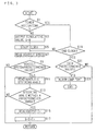
- FIG. 3 is a flow chart showing the operation of the electric power steering apparatus according to Embodiment 1 of the present invention.
- the torque sensor malfunction detection unit 8 checks whether or not the timer 9 is activated (during time counting or during outputting a time count terminating signal) (S1), and when it is not activated, the unit 8 sets the cumulative value S to be "0" (S3) and starts the timer 9 for the time count (S5).
- the torque sensor malfunction detection unit 8 reads the vehicle speed (signal) from the vehicle speed sensor 7 (S7), and checks whether or not the vehicle speed is higher than the predetermined value (S9). When the vehicle speed is higher than the predetermined value, the unit 8 reads the absolute steering angle from the subtracting means 21 (S11), and checks whether or not the absolute steering angle is within the predetermined range (S13).
- the torque sensor malfunction detection unit 8 when the absolute steering angle is within the predetermined range, reads a value Tr of the steering torque signal from the torque sensor 2 (S15), and adds the value to the cumulative value S (S17).
- the torque sensor malfunction detection unit 8 when the vehicle speed is lower than the predetermined value (S9) or when the absolute steering angle is not within the predetermined range (S13) , the unit 8 returns.
- the torque sensor malfunction detection unit 8 when the timer 9 is activated (S1) and has completed its time count (S19), compares the absolute value of the cumulative value S with the predetermined value (S21). As a result, when the absolute value of the cumulative value S is higher than the predetermined value, the unit 8 judges that the torque sensor 2 has been failed and turns the alarm lamp 4 on via the alarm lamp drive unit 3 (S23). In case the absolute value of the cumulative value S is lower than the predetermined value (S21), the unit 8 returns.
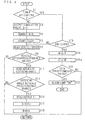
- FIG. 4 is a flow chart showing an operation of the electric power steering apparatus according to Embodiment 2 of the present invention. Since the constitution of the essential part of the electric power steering apparatus according to Embodiment 2 of the present invention is similar to that of the electric power steering apparatus according to Embodiment 1 of the present invention as described above, further description about the constitution will be omitted.
- the torque sensor malfunction detection unit 8 cumulates the value Tr of the steering torque signal from the torque sensor 2 for the predetermined period of time counted by the timer 9, calculates a difference between the average value of the steering torque signal obtained from the cumulated value and the value to be output by the torque sensor 2 at its neutral point, compares the absolute value of the difference with the predetermined value, when the absolute value of the difference is higher than the predetermined value, judges that the torque sensor 2 has been failed, and turns the alarm lamp 4 on via the alarm lamp drive unit 3.
- the torque sensor malfunction detection unit 8 checks whether or not the timer 9 is activated (during time counting or during outputting time count terminating signal) (S1), and when the timer 9 is not activated, the unit 8 sets the output cumulative value S to "0" (S3) and the cumulated number of times N to "0" (S4), and starts the timer 9 for the time count (S5).
- the torque sensor malfunction detection unit 8 reads the vehicle speed (signal) from the vehicle speed sensor 7 (S7) to check whether or not the vehicle speed is higher than the predetermined value (S9).
- the unit 8 reads the absolute steering angle from the subtracting means 21 (S11) and checks whether or not the absolute steering angle is within the predetermined range (S13).
- the torque sensor malfunction detection unit 8 reads the value Tr of the steering torque signal from the torque sensor 2 (S15), adds it to the cumulative value S (S17), and adds "1" to the number of times N (S18).
- the torque sensor malfunction detection unit 8 returns when the vehicle speed is lower than the predetermined value (S9) or when the absolute steering angle is not within the predetermined range (S13).
- the torque sensor malfunction detection unit 8 compares the absolute value of the difference E with the predetermined value (S22), and as a result, when the absolute value of the difference E is higher than the predetermined value, the unit 8 judges that the torque sensor 2 is failed, turns the alarm lamp 4 on via the alarm lamp drive unit 3 (S23). In case the absolute value of the difference E is lower than the predetermined value (S22), the unit 8 returns.
- FIG. 5 is a block diagram showing the constitution of an essential part of the electric power steering apparatus according to Embodiment 3 of the present invention.
- the vehicle speed signal from the vehicle speed sensor 7 is given to the assist control unit 12.
- the motor rotational speed signal from the motor rotary sensor 18 which detects the rotational speed of the motor 5 for steering force assistance is given to the relative steering angle detection unit 19.
- the relative steering angle detection unit 19 detects the relative steering angle of the steering wheel based on the motor rotational speed signal and gives it to a steering angular velocity detection unit 24.
- the steering angular velocity detection unit 24 calculates a steering angular velocity based on the given relative steering angle, and gives the calculation results to a torque sensor malfunction detection unit 8a.
- the torque sensor malfunction detection unit 8a cumulates the value Tr of the steering torque signal from the torque sensor 2 for a predetermined time counted by the timer 9, compares the absolute value of the cumulated value with the predetermined value, and when the absolute value of the cumulated value is higher than the predetermined value, it judges that the torque sensor 2 has been failed, and turns the alarm lamp 4 on via the alarm lamp drive unit 3. Since the constitution of the other part is similar to that of the essential part of the electric power steering apparatus according to Embodiment 1 of the present invention as described above, further description about the constitution will be omitted.
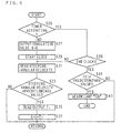
- FIG. 6 is a flow chart showing the operation of the electric power steering apparatus according to Embodiment 3 of the present invention.
- the torque sensor malfunction detection unit 8a checks whether or not the timer 9 is activated (S25), and if it is not activated, the unit 8a sets the output cumulated value to "0" (S27) to start the timer 9 for its time count (S29).
- the torque sensor malfunction detection unit 8a reads the steering angular velocity from the steering angular velocity detection unit 24 (S31) and checks whether or not the steering angular velocity is lower than the predetermined value (S33). When the steering angular velocity is lower than the predetermined value, the unit 8a reads the value Tr of the steering torque signal from the torque sensor 2 (S35) and adds it to the cumulative value S (S37). When the steering angular velocity is higher than the predetermined value (S33), the torque sensor malfunction detection unit 8a returns.
- the torque sensor malfunction detection unit 8a compares the absolute value of the cumulative value S with the predetermined value (S41), and as a result, when the absolute value of the cumulative value S is higher than the predetermined value, the unit 8a judges that the torque sensor 2 has been failed, and turns the alarm lamp 4 on via the alarm lamp drive unit 3 (S43). In case the absolute value of the cumulative value S is lower than the predetermined value (S41), the unit 8 returns.
- FIG. 7 is a flow chart showing an operation of the electric power steering apparatus according to Embodiment 4 of the present invention. Since the constitution of the essential part of the electric power steering apparatus according to Embodiment 4 of the present invention is similar to that of the electric power steering apparatus according to Embodiment 3 of the present invention as described above, further description about the constitution will be omitted.
- the torque sensor malfunction detection unit 8a cumulates the value Tr of the steering torque signal from the torque sensor 2 for a predetermined period of time counted by the timer 9, calculates the difference between an average value of the steering torque signal obtained from the cumulated value and the value to be output by the torque sensor 2 at its neutral point, compares the absolute value of the difference with the predetermined value, and when the absolute value of the difference is higher than the predetermined value, the unit 8a judges that the torque sensor 2 has been failed, and turns the alarm lamp 4 on via the alarm lamp drive unit 3.
- the torque sensor malfunction detection unit 8a checks whether or not the timer 9 is activated (S25), and when it is not activated, the unit 8a sets the output cumulative value S to "0" (S27) and the cumulated number of times N to "0" (S28), and activates the timer 9 for its time count (S29).
- the torque sensor malfunction detection unit 8a reads the steering angular velocity from the steering angular velocity detection unit 24 (S31) and checks whether or not the steering angular velocity is lower than the predetermined value (S33). When the steering angular velocity is lower than the predetermined value, the unit 8a reads the value Tr of the steering torque signal from the torque sensor 2 (S35), adds it to the cumulative value S (S37), and adds "1" to the number of times N (S38).
- the torque sensor malfunction detection unit 8 compares the absolute value of the difference E with the predetermined value (S42), and as a result, then the absolute value of the difference E is higher than the predetermined value, the unit 8 judges that the torque sensor 2 has been failed and turns the alarm lamp 4 on via the alarm lamp drive unit 3 (S43). When the absolute value of the difference E is lower than the predetermined value (S42), the unit 8 returns.
- FIG. 8 is a block diagram showing the constitution of an essential part of the electric power steering apparatus according to Embodiment 5 of the present invention.
- the vehicle speed signal from the vehicle speed sensor 7 is given to the assist control unit 12.
- a detection signal for detecting "ON” or “OFF” of an ignition key (not illustrated) from an ignition key ON/OFF detection unit 10 is given to the torque sensor malfunction detection unit 8b.
- the torque sensor malfunction detection unit 8b cumulates the output values thereof, and when the cumulated number of times reaches the predetermined number of times, the unit 8b compares the absolute value of the cumulated value with a predetermined value, and when the absolute value of the cumulated value is higher than the predetermined value, the unit 8b judges that the torque sensor 2 has been failed, and turns the alarm lamp 4 on via the alarm lamp drive unit 3. Since the other constitution is similar to the constitution of the essential part of the electric power steering apparatus according to Embodiment 1 of the present invention as described above, further description about the constitution will be omitted.
- FIG. 9 is a flow chart showing the operation of the electric power steering apparatus according to Embodiment 5 of the present invention.
- the torque sensor malfunction detection unit 8a sets the output cumulative value S to "0" (S45), and turns the cumulated number of times N to "0" (S47).
- the torque sensor malfunction detection unit 8b checks whether or not the number of times N has reached a predetermined number of times (S49), and when the number of times has not reached the predetermined number of times, the unit 8b waits until the detection signal of "ON" operation of the ignition key is input from the ignition key ON/OFF detection unit 10 (S51).
- the torque sensor malfunction detection unit 8b reads the value Tr of the steering torque signal from the torque sensor 2 (S53), and checks whether or not the absolute value of the value Tr is higher than the predetermined value (S55).
- the torque sensor malfunction detection unit 8b adds the value Tr to the cumulative value S (S57).
- the torque sensor malfunction detection unit 8b adds "1" to the number of times N (S59), and checks whether or not the number of times N has reached the predetermined number of times (S49).
- the torque sensor malfunction detection unit 8b compares the absolute value of the cumulative value S with the predetermined value (S63), and when the absolute value of the cumulative value S is higher than the predetermined value, the unit 8b judges that the torque sensor 2 has been failed, and turns the alarm lamp 4 on via the alarm lamp drive unit 3 (S65). When the absolute value of the cumulative value S is lower than the predetermined value (S63), the step returns to S45.
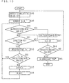
- FIG. 10 is a flow chart showing the operation of the electric power steering apparatus according to Embodiment 6 of the present invention.
- an essential part of the electric power steering apparatus according to Embodiment 6 of the present invention is similar to the constitution of the essential part of the electric power steering apparatus according to Embodiment 5 of the present invention, further description about the constitution will be omitted.
- the torque sensor malfunction detection unit 8b cumulates the output values thereof, and when the cumulated number of times reaches the predetermined number of times, the unit 8b obtains an average value M of the output values based on the cumulated value.
- the unit 8b calculates the difference between the value C to be output by the torque sensor 2 at its neutral point and the average value M, and compares the absolute value with a predetermined value, and when the absolute value of the difference is higher than the predetermined value, the unit 8b judges that the torque sensor 2 has been failed, and turns the alarm lamp 4 on via the alarm lamp drive unit 3.
- the torque sensor malfunction detection unit 8b sets the output cumulative value S to "0" (S45), and turns the cumulated number of times N to "0" (S47).
- the torque sensor malfunction detection unit 8b checks whether or not the number of times N has reached a predetermined number of times (S49), and if not reached the predetermined number of times, the unit 8b waits until the detection signal of an "ON" operation of the ignition key is input from the ignition ON/OFF detection unit 10 (S51).
- the torque sensor malfunction detection unit 8b reads the value Tr of the steering torque signal from the torque sensor 2 (S53), and checks whether or not the absolute value of the value Tr is higher than the predetermined value (S55).
- the torque sensor malfunction detection unit 8b adds the value Tr to the cumulative value S (S57).
- the torque sensor malfunction detection unit 8b adds "1" to the number of times N (S59), and checks whether or not the number of times N has reached the predetermined number of times (S49).
- the torque sensor malfunction detection unit 8b compares the absolute value of the difference E with the predetermined value (S64), and as a result, when the absolute value of the difference E is higher than the predetermined value, the unit 8b judges that the torque sensor 2 has been failed, and turns the alarm lamp 4 on via the alarm lamp drive unit 3 (S65). When the absolute value of the difference E is lower than the predetermined value (S64), the step returns to S45.
- FIG. 11 is a flow chart showing the operation of the electric power steering apparatus according to Embodiment 7 of the present invention.
- the constitution of an essential part of the electric power steering apparatus according to Embodiment 7 of the present invention is similar to the constitution of the essential part of the electric power steering apparatus according to Embodiment 5 of the present invention, further description about the constitution will be omitted.
- the torque sensor malfunction detection unit 8b sets the output cumulative value S to "0" (S67), and the cumulated number of times N to be "0" (S69).
- the torque sensor malfunction detection unit 8b checks whether or not the number of times N has reached a predetermined number of times (S71), and if not reached the predetermined number of times, the unit 8b waits until the detection signal of the "OFF" operation of the ignition key is input from the ignition ON/OFF detection unit 10 (S73).
- the torque sensor malfunction detection unit 8b reads the value Tr of the steering torque signal from the torque sensor 2 (S75), and checks whether or not the absolute value of the value Tr is higher than the predetermined value (S77).
- the torque sensor malfunction detection unit 8b adds the value Tr to the cumulative value S (S79).
- the torque sensor malfunction detection unit 8b adds "1" to the number of times N (S81), and checks whether or not the number of times N has reached the predetermined number of times (S71) .
- the torque sensor malfunction detection unit 8b compares the absolute value of the cumulative value S with the predetermined value (S85), and when the absolute value of the cumulated value is higher than the predetermined value, the unit 8b judges that the torque sensor 2 has been failed, and turns the alarm lamp 4 on via the alarm lamp drive unit 3 (S87). When the absolute value of the cumulative value S is lower than the predetermined value (S85), the step returns to S67.
- FIG. 12 is a flow chart showing the operation of the electric power steering apparatus according to Embodiment 8 of the present invention.
- a constitution of the essential part of the electric power steering apparatus according to Embodiment 8 of the present invention is similar to the constitution of the essential part of the electric power steering apparatus according to Embodiment 5 of the present invention, further description about the constitution will be omitted.
- the torque sensor malfunction detection unit 8b cumulates the output values thereof, and when the cumulated number of times reaches a predetermined number of times, the unit 8b obtains an average value M of the output values based on the cumulated value.
- the unit 8b calculates the difference between the value C to be output by the torque sensor 2 at its neutral point and the average value M, and compares the absolute value of the difference with the predetermined value, and when the absolute value of the difference is higher than the predetermined value, the unit 8b judges that the torque sensor 2 has been failed, and turns the alarm lamp 4 on via the alarm lamp drive unit 3.
- the torque sensor malfunction detection unit 8b sets the output cumulative value S to "0" (S67), and the cumulated number of times N to be "0" (S69).
- the torque sensor malfunction detection unit 8b checks whether or not the number of times N has reached a predetermined number of times (S71), and if not reached the predetermined number of times, the unit 8b waits until the detection signal of the "OFF" operation of the ignition key is input from the ignition ON/OFF detection unit 10 (S73).
- the torque sensor malfunction detection unit 8b reads the value Tr of the steering torque signal from the torque sensor 2 (S75), and checks whether or not the absolute value of the value Tr is higher than the predetermined value (S77).
- the torque sensor malfunction detection unit 8b adds the value Tr to the cumulative value S (S79).
- the torque sensor malfunction detection unit 8b adds "1" to the number of times N (S81), and checks whether or not the number of times N has reached the predetermined number of times (S71) .
- the torque sensor malfunction detection unit 8b compares the absolute value of the difference E with the predetermined value (S86), and as a result, when the absolute value of the difference E is higher than the predetermined value, the unit 8b judges that the torque sensor 2 has been failed, and turns the alarm lamp 4 on via the alarm lamp drive unit 3 (S87). When the absolute value of the difference E is lower than the predetermined value (S86), the step returns to S67.
- FIG. 13 is a block diagram showing the constitution of an essential part of the electric power steering apparatus according to Embodiment 9 of the present invention.
- the vehicle speed signal from the vehicle speed sensor 7 is given to the assist control unit 12.
- a detection signal of a stopper detection unit 17 detecting that the torque sensor 2 has reached to a mechanical stopper is given to the torque sensor malfunction detection unit 8c.
- the torque sensor malfunction detection unit 8c memorizes output values of the torque sensor 2 when the stopper detection unit 17 detects that the torque sensor 2 has reached the mechanical stopper. Thereafter, at each time of the detection by the stopper detection unit 17 for the above reach, the unit 8c calculates the difference between the output value of the torque sensor 2 at that time and the memorized output value, then compares the absolute value of the difference with the predetermined value, and when the absolute value of the difference is higher than a predetermined value, the unit 8c judges that the torque sensor 2 has been failed, and turns the alarm lamp 4 "ON" via the alarm lamp drive unit 3.
- the unit 8c judges that the torque sensor 2 has been failed, and turns the alarm lamp 4 "ON" via the alarm lamp drive unit 3.
- FIG. 14 is a flow chart showing the operation of the electric power steering apparatus according to Embodiment 9 of the present invention.
- the torque sensor malfunction detection unit 8c when the detection signal is given from the stopper detection unit 17 (S89), reads the output value Tr of the torque sensor 2 (S91), and memorizes the output value Tr (S93).
- the torque sensor malfunction detection unit 8c reads the output value Trn of the torque sensor 2 at that time (S97) and calculates the difference between the memorized output value Tr and the read output value Trn (S99). Then, the unit 8c compares the absolute value of the difference with a predetermined value (S101), and when the absolute value of the difference is higher than the predetermined value, the unit 8c judges that the torque sensor 2 has been failed, and turns the alarm lamp 4 "ON" via the alarm lamp drive unit 3 (S103).
- the torque sensor malfunction detection unit 8c deletes the read output value Trn (S105) and waits until the next detection signal is given from the stopper detection unit 17 (S95).
Landscapes
- Engineering & Computer Science (AREA)
- Chemical & Material Sciences (AREA)
- Combustion & Propulsion (AREA)
- Transportation (AREA)
- Mechanical Engineering (AREA)
- Power Steering Mechanism (AREA)
- Steering Control In Accordance With Driving Conditions (AREA)
Claims (10)
- Elektrische Servolenkvorrichtung zum Unterstützen des Lenkens auf der Basis eines Ausgangssignals eines Drehmomentsensors (2), der ein Lenk-Drehmoment detektiert, gekennzeichnet durch:eine Kumulationseinrichtung (8,8a) zum Kumulieren des Ausgangssignals während einer vorbestimmten Zeitperiode;eine Vergleichseinrichtung (8,8a) zum Vergleichen eines Absolutwerts des von der Kumulationseinrichtung (8,8a) kumulierten Ergebnisses mit einem vorbestimmten Wert; undeine Einrichtung (8,8a) zum Detektieren eines Versatzes eines Detektions-Neutralpunkts des Drehmomentsensors (2) auf der Basis der Ergebnisse des von der Vergleichseinrichtung (8,8a) durchgeführten Vergleichs.
- Elektrische Servolenkvorrichtung nach Anspruch 1, mit einer Einrichtung zum periodischen Abtasten eines Ausgangssignals des Drehmomentsensors (2) zwecks Unterstützens des Lenkvorgangs auf der Basis des abgetasteten Ausgangssignals, ferner gekennzeichnet durch:eine Zähleinrichtung (8,8a) zum Zählen der Anzahl der Kumulationsvorgänge der Kumulationseinrichtung (8,8a);eine Recheneinrichtung (8,8a) zum Berechnen eines Mittelwerts des Ausgangssignals auf der Basis des von der Kumulationseinrichtung (8,8a) kumulierten Kumulationswerts und der von der Zähleinrichtung (8,8a) gezählten Anzahl von Kumulationsvorgängen;eine Einrichtung (8,8a) zum Berechnen einer Differenz zwischen einem von dem Drehmomentsensor (2) an seinem Neutralpunkt auszugebendem Wert und dem von der Recheneinrichtung (8,8a) berechneten Mittelwert; undeine Vergleichseinrichtung (8,8a) zum Vergleichen eines Absolutwerts der von der Recheneinrichtung (8,8a) berechneten Differenz mit einem vorbestimmten Wert.
- Elektrische Servolenkvorrichtung nach Anspruch 1 oder 2, ferner mit:wobei die Kumulationseinrichtung (8) eine Kumulation durchführt, wenn die von dem Fahrzeuggeschwindigkeitssensor (7) detektierte Fahrzeuggeschwindigkeit höher als eine vorbestimmte Fahrzeuggeschwindigkeit ist und der von der Lenkwinkeldetektionseinrichtung (18,19,20,21) detektierte Lenkwinkel innerhalb eines vorbestimmten Bereichs liegt.einem Fahrzeuggeschwindigkeitssensor (7) zum Detektieren der Fahrzeuggeschwindigkeit; undeiner Lenkwinkeldetektionseinrichtung (18,19,20,21) zum Detektieren eines Lenkwinkels,
- Elektrische Servolenkvorrichtung nach Anspruch 1 oder 2, ferner mit:wobei die Kumulationseinrichtung (8,8a) eine Kumulation durchführt, wenn die von der Lenkwinkeigeschwindigkeits-Detektionseinrichtung (18,19,24) detektierte Lenkwinkelgeschwindigkeit niedriger als eine vorbestimmte Lenkwinkelgeschwindigkeit ist.einer Lenkwinkelgeschwindigkeits-Detektionseinrichtung (18,19,24) zum Detektieren einer Lenkwinkelgeschwindigkeit,
- Elektrische Servolenkvorrichtung nach einem der Ansprüche 1-4, gekennzeichnet durch:wobei die Kumulationseinrichtung (8b) das Ausgangssignal des Drehmomentsensors (2) jedes Mal kumuliert, wenn die zum Detektieren vorgesehene Einrichtung (10) eine vorbestimmte Anzahl der "EIN"-Operationen detektiert.eine Einrichtung zum Detektieren einer "EIN"-Operation eines Zündschlüssels;
- Elektrische Servolenkvorrichtung nach einem der Ansprüche 1-5, gekennzeichnet durch:wobei die Kumulationseinrichtung (8a) das Ausgangssignal des Drehmomentsensors (2) jedes Mal kumuliert, wenn die zum Detektieren einer "EIN"-Operation vorgesehene Einrichtung (10) eine vorbestimmte Anzahl der "EIN"-Operationen detektiert;eine Einrichtung (10) zum Detektieren einer "EIN"-Operation eines Zündschlüssels;
eine Recheneinrichtung (8b) zum Berechnen eines Mittelwerts des Ausgangssignals auf der Basis des von der Kumulationseinrichtung (8b) kumulierten Kumulationswerts;
eine Einrichtung (8b) zum Berechnen der Differenz zwischen einem von dem Drehmomentsensor (2) an seinem Neutralpunkt auszugebendem Wert und dem von der Recheneinrichtung (8b) berechneten Mittelwert; und
eine Vergleichseinrichtung (8b) zum Vergleichen eines Absolutwerts der von der Recheneinrichtung (8b) berechneten Differenz mit einem vorbestimmten Wert; und
eine Einrichtung (8b) zum Detektieren eines Versatzes eines Detektions-Neutralpunkts des Drehmomentsensors (2) auf der Basis der Ergebnisse des von der Vergleichseinrichtung (8b) durchgeführten Vergleichs. - Elektrische Servolenkvorrichtung nach einem der Ansprüche 1-6, gekennzeichnet durch:eine Einrichtung (10) zum Detektieren einer "AUS"-Operation eines Zündschlüssels;eine Kumulationseinrichtung (8b) zum Kumulieren des Ausgangssignals des Drehmomentsensors (2) jedes Mal, wenn die zum Detektieren vorgesehene Einrichtung (10) eine vorbestimmte Anzahl der "AUS"-Operationen detektiert;eine Vergleichseinrichtung (8b) zum Vergleichen eines Absolutwerts des von der Kumulationseinrichtung (8b) kumulierten Kumulationswerts mit einem vorbestimmten Wert; undeine Einrichtung (8b) zum Detektieren eines Versatzes eines Detektions-Neutralpunkts des Drehmomentsensors (2) auf der Basis der Ergebnisse des von der Vergleichseinrichtung (8b) durchgeführten Vergleichs.
- Elektrische Servolenkvorrichtung nach einem der Ansprüche 1-6, gekennzeichnet durch:eine Einrichtung (10) zum Detektieren einer "AUS"-Operation eines Zündschlüssels;eine Kumulationseinrichtung (8b) zum Kumulieren des Ausgangssignals des Drehmomentsensors (2) jedes Mal, wenn die zum Detektieren vorgesehene Einrichtung (10) eine vorbestimmte Anzahl der "AUS"-Operationen detektiert;eine Recheneinrichtung (8b) zum Berechnen eines Mittelwerts des Ausgangssignals auf der Basis des von der Kumulationseinrichtung (8b) kumulierten Kumulationswerts;eine Einrichtung (8b) zum Berechnen der Differenz zwischen einem von dem Drehmomentsensor (2) an seinem Neutralpunkt auszugebendem Wert und dem von der Recheneinrichtung (8b) berechneten Mittelwert; undeine Vergleichseinrichtung (8b) zum Vergleichen eines Absolutwerts der von der Recheneinrichtung (8b) berechneten Differenz mit einem vorbestimmten Wert.
- Elektrische Servolenkvorrichtung nach einem der Ansprüche 5 bis 8, ferner mit:wobei die Kumulationseinrichtung (8b) eine Kumulation durchführt, wenn die Prüfeinrichtung (8b) erkennt, dass das Ausgangssignal in dem vorbestimmten Bereich liegt.einer Einrichtung (8b) zum Prüfen, ob das Ausgangssignal des Drehmomentsensors (2) in einem vorbestimmten Bereich liegt oder nicht;
- Elektrische Servolenkvorrichtung nach einem der Ansprüche 1-9, bei der der Drehmomentsensor (2) einen mechanischen Anschlag zum Verhindern durch Übersteuerung verursachten Brechens aufweist und ein Lenk-Drehmoment detektiert, gekennzeichnet durch:eine Anschlagdetektionseinrichtung (17) zum Detektieren eines Erreichens des mechanischen Anschlags durch den Drehmomentsensor (2);eine Speichereinrichtung (8c) zum Speichern des Ausgangssignals des Drehmomentsensors (2), wenn die Anschlagdetektionseinrichtung (17) das Erreichen detektiert;eine Einrichtung (8c) zum Berechnen der Differenz zwischen dem Ausgangssignal des Drehmomentsensors (2) und dem in der Speichereinrichtung (8c) gespeicherten Ausgangssignal, wobei die Anschlagdetektionseinrichtung (17) das Ausgangssignal nach dem Erreichen beim nächsten Mal detektiert, wenn der Drehmomentsensor (2) den mechanischen Anschlag erreicht;eine Vergleichseinrichtung (8c) zum Vergleichen eines Absolutwerts des von der Recheneinrichtung (8c) berechneten Differenz mit einem vorbestimmten Wert; undeine Einrichtung (8c) zum Detektieren eines Versatzes eines Detektions-Neutralpunkts des Drehmomentsensors (2) auf der Basis der Ergebnisse des von der Vergleichseinrichtung (8c) durchgeführten Vergleichs.
Applications Claiming Priority (3)
| Application Number | Priority Date | Filing Date | Title |
|---|---|---|---|
| JP23753897A JP3639942B2 (ja) | 1997-09-02 | 1997-09-02 | 電動パワーステアリング装置 |
| JP237538/97 | 1997-09-02 | ||
| JP23753897 | 1997-09-02 |
Publications (3)
| Publication Number | Publication Date |
|---|---|
| EP0900711A2 EP0900711A2 (de) | 1999-03-10 |
| EP0900711A3 EP0900711A3 (de) | 2000-06-14 |
| EP0900711B1 true EP0900711B1 (de) | 2003-12-17 |
Family
ID=17016826
Family Applications (1)
| Application Number | Title | Priority Date | Filing Date |
|---|---|---|---|
| EP98116491A Expired - Lifetime EP0900711B1 (de) | 1997-09-02 | 1998-09-01 | Elektrische Servolenkung |
Country Status (4)
| Country | Link |
|---|---|
| US (1) | US6240349B1 (de) |
| EP (1) | EP0900711B1 (de) |
| JP (1) | JP3639942B2 (de) |
| DE (1) | DE69820549T2 (de) |
Families Citing this family (29)
| Publication number | Priority date | Publication date | Assignee | Title |
|---|---|---|---|---|
| JP2000053011A (ja) * | 1998-08-03 | 2000-02-22 | Koyo Seiko Co Ltd | 舵角中点検出装置及びパワーステアリング装置 |
| JP3636926B2 (ja) * | 1999-05-11 | 2005-04-06 | 光洋精工株式会社 | 車両用操舵装置 |
| US6448728B2 (en) * | 2000-03-31 | 2002-09-10 | Honda Giken Kabushiki Kaisha | Electric power steering apparatus |
| JP3700547B2 (ja) * | 2000-06-29 | 2005-09-28 | 三菱電機株式会社 | 電動式パワーステアリング装置 |
| JP4061980B2 (ja) * | 2002-01-15 | 2008-03-19 | 株式会社ジェイテクト | 電動パワーステアリング装置 |
| JP4269677B2 (ja) * | 2002-12-24 | 2009-05-27 | 株式会社ジェイテクト | 電動パワーステアリング装置 |
| JP4193113B2 (ja) * | 2003-02-27 | 2008-12-10 | 株式会社ジェイテクト | 電動パワーステアリング装置 |
| US6983817B2 (en) * | 2003-03-18 | 2006-01-10 | Toyoda Koki Kabushiki Kaisha | Power steering device |
| US6909951B2 (en) * | 2003-09-12 | 2005-06-21 | Dana Corporation | Fail-safe torque transducer system |
| FR2876973B1 (fr) * | 2004-10-26 | 2006-12-08 | Koyo Steering Europ K S E Soc | Procede de correction des mesures du couple exerce sur un volant de conduite d'une direction assistee electrique de vehicule automobile |
| JP4774740B2 (ja) * | 2005-01-06 | 2011-09-14 | 株式会社ジェイテクト | 電動パワーステアリング装置 |
| FR2892085B1 (fr) * | 2005-10-19 | 2007-11-23 | Koyo Steering Europ Soc Par Ac | Procede pour determiner en temps reel la tenue d'un volant de conduite d'une direction assistee electrique de vehicule automobile |
| JP2007161157A (ja) * | 2005-12-15 | 2007-06-28 | Nsk Ltd | 電動パワーステアリング装置 |
| JP4835148B2 (ja) * | 2005-12-19 | 2011-12-14 | 株式会社ジェイテクト | 電動パワーステアリング装置 |
| DE102007003783A1 (de) | 2007-01-19 | 2008-07-24 | Zf Lenksysteme Gmbh | Verfahren und Steuergerät zum Betrieb einer elektrischen Servolenkung |
| DE102008054424B4 (de) | 2008-12-09 | 2020-09-03 | Robert Bosch Gmbh | Verfahren und Vorrichtung zur Steuerung eines Antriebstrangs |
| KR101313935B1 (ko) * | 2009-10-15 | 2013-10-14 | 주식회사 만도 | 조향각 센서 초기화 고장 검출 방법 및 장치 |
| US9205869B2 (en) | 2010-08-16 | 2015-12-08 | Honda Motor Co., Ltd. | System and method for determining a steering angle for a vehicle and system and method for controlling a vehicle based on same |
| JP5961566B2 (ja) | 2012-03-13 | 2016-08-02 | Kyb株式会社 | トルクセンサの異常診断装置及び異常診断方法 |
| CN104661896B (zh) * | 2013-03-07 | 2016-11-23 | 日本精工株式会社 | 电动助力转向装置 |
| JP5945764B2 (ja) | 2013-03-21 | 2016-07-05 | 日立オートモティブシステムズ株式会社 | パワーステアリング装置 |
| JP6053651B2 (ja) * | 2013-09-20 | 2016-12-27 | 日立オートモティブシステムズ株式会社 | パワーステアリング装置および車両搭載機器の制御装置 |
| JP6078444B2 (ja) * | 2013-09-20 | 2017-02-08 | 日立オートモティブシステムズ株式会社 | パワーステアリング装置および車両搭載機器の制御装置 |
| CN105292243B (zh) * | 2015-09-29 | 2017-07-07 | 桂林电子科技大学 | 汽车电动助力转向系统的预测控制方法 |
| JP2017077830A (ja) * | 2015-10-21 | 2017-04-27 | Kyb株式会社 | 電動パワーステアリング装置 |
| JP2018008652A (ja) * | 2016-07-15 | 2018-01-18 | 株式会社ジェイテクト | ステアリング装置 |
| US10071764B2 (en) * | 2016-11-11 | 2018-09-11 | Steering Solutions Ip Holding Corporation | Methods to control a steering system |
| GB201619479D0 (en) * | 2016-11-17 | 2017-01-04 | Trw Ltd | Electric power assisted steering system |
| CN113276938B (zh) * | 2021-06-09 | 2023-01-06 | 重庆长安汽车股份有限公司 | Eps扭矩传感器零位扭矩偏差自学习及纠正方法、系统及车辆 |
Family Cites Families (10)
| Publication number | Priority date | Publication date | Assignee | Title |
|---|---|---|---|---|
| JP2608435B2 (ja) | 1987-12-29 | 1997-05-07 | カヤバ工業株式会社 | 電動パワーステアリング装置のフェイルセイフ装置 |
| JPH01270627A (ja) * | 1988-04-22 | 1989-10-27 | Hitachi Ltd | トルクセンサ保護装置 |
| JPH07115643B2 (ja) * | 1988-04-28 | 1995-12-13 | 三菱電機株式会社 | 電動式パワーステアリング装置 |
| JPH01285460A (ja) * | 1988-05-13 | 1989-11-16 | Mitsubishi Electric Corp | 電動式パワーステアリング装置 |
| DE69005188T2 (de) * | 1989-05-19 | 1994-06-30 | Nissan Motor | Vorrichtung zur Fehlerfeststellung in einem Steuersystem für den Betrieb einer Last. |
| JP3094483B2 (ja) * | 1991-02-28 | 2000-10-03 | スズキ株式会社 | 電動パワステ用トルクセンサ異常検出装置 |
| FR2705453B1 (fr) * | 1993-05-17 | 1995-07-07 | Valeo Systemes Dessuyage | Capteur à redondance capteur de couple et système de direction assistée de véhicule. |
| JP3212215B2 (ja) * | 1994-03-17 | 2001-09-25 | 三菱電機株式会社 | 電動パワーステアリング制御装置 |
| JP3572471B2 (ja) * | 1996-02-21 | 2004-10-06 | 光洋精工株式会社 | 電動パワーステアリング装置 |
| US5881936A (en) * | 1998-03-24 | 1999-03-16 | Li; Bernard A. | Motorcycle caddy |
-
1997
- 1997-09-02 JP JP23753897A patent/JP3639942B2/ja not_active Expired - Fee Related
-
1998
- 1998-09-01 EP EP98116491A patent/EP0900711B1/de not_active Expired - Lifetime
- 1998-09-01 DE DE69820549T patent/DE69820549T2/de not_active Expired - Lifetime
- 1998-09-02 US US09/146,230 patent/US6240349B1/en not_active Expired - Fee Related
Also Published As
| Publication number | Publication date |
|---|---|
| EP0900711A3 (de) | 2000-06-14 |
| JPH1178921A (ja) | 1999-03-23 |
| EP0900711A2 (de) | 1999-03-10 |
| US6240349B1 (en) | 2001-05-29 |
| DE69820549T2 (de) | 2004-09-30 |
| DE69820549D1 (de) | 2004-01-29 |
| JP3639942B2 (ja) | 2005-04-20 |
Similar Documents
| Publication | Publication Date | Title |
|---|---|---|
| EP0900711A2 (de) | Elektrische Servolenkung | |
| US4856607A (en) | Apparatus for automatically setting steering center for use in power steering apparatus | |
| EP0350818B1 (de) | Servolenkung und Rotationsdetektor | |
| EP1923299B1 (de) | Vorrichtung zur Erkennung eines absoluten Lenkwinkels | |
| US5065325A (en) | Device for determining malfunctioning of electric-motor-assisted power steering system of motor vehicle | |
| KR100940534B1 (ko) | 전동 파워스티어링 장치 | |
| EP0304491B1 (de) | Motorbetriebene servolenkung für fahrzeuge | |
| US5101922A (en) | Rear wheel steering system with fail-safe system | |
| KR960005848B1 (ko) | 전동파워 스티어링 제어장치 및 방법 | |
| EP0061501A1 (de) | Warnsystem für einen einschlafenden fahrer | |
| EP0247736B1 (de) | Motorbetriebene Servolenkung für Fahrzeuge | |
| US7016775B2 (en) | Controller and control method for an electric power steering apparatus | |
| JP3094483B2 (ja) | 電動パワステ用トルクセンサ異常検出装置 | |
| JP2817556B2 (ja) | 電気式パワーステアリング装置における電動モータの異常検出装置 | |
| JPH10258757A (ja) | 操舵制御装置 | |
| JP4228474B2 (ja) | パワーステアリング制御装置 | |
| JP3987012B2 (ja) | 操舵トルク検出手段の故障検出装置 | |
| JP3261736B2 (ja) | 電動パワーステアリング装置 | |
| JPH05319296A (ja) | モータ駆動式パワーステアリング制御装置 | |
| KR100214995B1 (ko) | 롤각 측정용 장치 및 그 운영방법 | |
| JP2817560B2 (ja) | 車両用電気式パワーステアリング装置 | |
| JPH0730453Y2 (ja) | 電気式動力舵取装置 | |
| JPH0431173A (ja) | 電動式パワーステアリング装置 | |
| JPH1159464A (ja) | 電動モータ駆動式転舵制御装置 | |
| JPH06107204A (ja) | 車両の後輪操舵装置 |
Legal Events
| Date | Code | Title | Description |
|---|---|---|---|
| PUAI | Public reference made under article 153(3) epc to a published international application that has entered the european phase |
Free format text: ORIGINAL CODE: 0009012 |
|
| AK | Designated contracting states |
Kind code of ref document: A2 Designated state(s): DE FR GB IT |
|
| AX | Request for extension of the european patent |
Free format text: AL;LT;LV;MK;RO;SI |
|
| PUAL | Search report despatched |
Free format text: ORIGINAL CODE: 0009013 |
|
| AK | Designated contracting states |
Kind code of ref document: A3 Designated state(s): AT BE CH CY DE DK ES FI FR GB GR IE IT LI LU MC NL PT SE |
|
| AX | Request for extension of the european patent |
Free format text: AL;LT;LV;MK;RO;SI |
|
| 17P | Request for examination filed |
Effective date: 20000707 |
|
| AKX | Designation fees paid |
Free format text: DE FR GB IT |
|
| 17Q | First examination report despatched |
Effective date: 20020510 |
|
| GRAH | Despatch of communication of intention to grant a patent |
Free format text: ORIGINAL CODE: EPIDOS IGRA |
|
| GRAS | Grant fee paid |
Free format text: ORIGINAL CODE: EPIDOSNIGR3 |
|
| GRAA | (expected) grant |
Free format text: ORIGINAL CODE: 0009210 |
|
| AK | Designated contracting states |
Kind code of ref document: B1 Designated state(s): DE FR GB IT |
|
| REG | Reference to a national code |
Ref country code: GB Ref legal event code: FG4D |
|
| REF | Corresponds to: |
Ref document number: 69820549 Country of ref document: DE Date of ref document: 20040129 Kind code of ref document: P |
|
| ET | Fr: translation filed | ||
| PLBE | No opposition filed within time limit |
Free format text: ORIGINAL CODE: 0009261 |
|
| STAA | Information on the status of an ep patent application or granted ep patent |
Free format text: STATUS: NO OPPOSITION FILED WITHIN TIME LIMIT |
|
| 26N | No opposition filed |
Effective date: 20040920 |
|
| PGFP | Annual fee paid to national office [announced via postgrant information from national office to epo] |
Ref country code: GB Payment date: 20070829 Year of fee payment: 10 |
|
| PGFP | Annual fee paid to national office [announced via postgrant information from national office to epo] |
Ref country code: IT Payment date: 20070927 Year of fee payment: 10 |
|
| GBPC | Gb: european patent ceased through non-payment of renewal fee |
Effective date: 20080901 |
|
| PG25 | Lapsed in a contracting state [announced via postgrant information from national office to epo] |
Ref country code: IT Free format text: LAPSE BECAUSE OF NON-PAYMENT OF DUE FEES Effective date: 20080901 |
|
| PG25 | Lapsed in a contracting state [announced via postgrant information from national office to epo] |
Ref country code: GB Free format text: LAPSE BECAUSE OF NON-PAYMENT OF DUE FEES Effective date: 20080901 |
|
| PGFP | Annual fee paid to national office [announced via postgrant information from national office to epo] |
Ref country code: DE Payment date: 20090827 Year of fee payment: 12 |
|
| PGFP | Annual fee paid to national office [announced via postgrant information from national office to epo] |
Ref country code: FR Payment date: 20091012 Year of fee payment: 12 |
|
| REG | Reference to a national code |
Ref country code: FR Ref legal event code: ST Effective date: 20110531 |
|
| REG | Reference to a national code |
Ref country code: DE Ref legal event code: R119 Ref document number: 69820549 Country of ref document: DE Effective date: 20110401 |
|
| PG25 | Lapsed in a contracting state [announced via postgrant information from national office to epo] |
Ref country code: DE Free format text: LAPSE BECAUSE OF NON-PAYMENT OF DUE FEES Effective date: 20110401 Ref country code: FR Free format text: LAPSE BECAUSE OF NON-PAYMENT OF DUE FEES Effective date: 20100930 |