EP0901431B1 - Dispositif de fixation - Google Patents
Dispositif de fixation Download PDFInfo
- Publication number
- EP0901431B1 EP0901431B1 EP97921066A EP97921066A EP0901431B1 EP 0901431 B1 EP0901431 B1 EP 0901431B1 EP 97921066 A EP97921066 A EP 97921066A EP 97921066 A EP97921066 A EP 97921066A EP 0901431 B1 EP0901431 B1 EP 0901431B1
- Authority
- EP
- European Patent Office
- Prior art keywords
- airbag module
- steering wheel
- airbag
- console
- attenuating element
- Prior art date
- Legal status (The legal status is an assumption and is not a legal conclusion. Google has not performed a legal analysis and makes no representation as to the accuracy of the status listed.)
- Expired - Lifetime
Links
Images


Classifications
-
- B—PERFORMING OPERATIONS; TRANSPORTING
- B60—VEHICLES IN GENERAL
- B60R—VEHICLES, VEHICLE FITTINGS, OR VEHICLE PARTS, NOT OTHERWISE PROVIDED FOR
- B60R21/00—Arrangements or fittings on vehicles for protecting or preventing injuries to occupants or pedestrians in case of accidents or other traffic risks
- B60R21/02—Occupant safety arrangements or fittings, e.g. crash pads
- B60R21/16—Inflatable occupant restraints or confinements designed to inflate upon impact or impending impact, e.g. air bags
- B60R21/20—Arrangements for storing inflatable members in their non-use or deflated condition; Arrangement or mounting of air bag modules or components
- B60R21/203—Arrangements for storing inflatable members in their non-use or deflated condition; Arrangement or mounting of air bag modules or components in steering wheels or steering columns
- B60R21/2035—Arrangements for storing inflatable members in their non-use or deflated condition; Arrangement or mounting of air bag modules or components in steering wheels or steering columns using modules containing inflator, bag and cover attachable to the steering wheel as a complete sub-unit
- B60R21/2037—Arrangements for storing inflatable members in their non-use or deflated condition; Arrangement or mounting of air bag modules or components in steering wheels or steering columns using modules containing inflator, bag and cover attachable to the steering wheel as a complete sub-unit the module or a major component thereof being yieldably mounted, e.g. for actuating the horn switch or for protecting the driver in a non-deployment situation
Definitions
- the present invention relates to a device for suspending an airbag module in a motor vehicle, according to the preamble of appended claim 1.
- the invention relates to a device in which an airbag module in the steering wheel device of the vehicle is adjusted to function as a tuned vibration attenuator.
- Modern motor vehicles are often equipped with at least one airbag in order to protect those travelling in the vehicle.
- this airbag is arranged to, in case of a collision with the vehicle, be activated by means of an acceleration sensor and to be inflated by means of a gas generator, so that gas flows into the airbag which is then formed to a soft cushion which suppresses the forward motion of the person travelling in the vehicle.
- the driver of the vehicle he is normally protected by means of an airbag which is arranged in the hub of the steering wheel of the vehicle.
- an airbag module which comprises the airbag and the gas generator used for inflating the airbag can be arranged in the hub of the steering wheel.
- the steering wheel When the engine idles the steering wheel normally vibrates at a certain frequency, which frequency is ca. 30-40 Hz in modern vehicles. If an airbag module of the above-mentioned kind is arranged in the steering wheel, a considerable weight is added, which might cause the natural frequency of the steering system of the vehicle to decrease. In case of unfavourable circumstances which i.a. depend on the choice of idling rpm of the engine, the natural frequency can interact with the idling frequency of the engine, thus causing greatly amplified vibrations in the steering wheel.
- the airbag module is furthermore arranged to activate an airbag in a predetermined manner.
- the airbag when triggered, to be inflated in a well defined direction relative to the person intended to be protected.
- a drawback of known suspension devices for airbag modules is that there is a risk that the airbag is inflated somewhat obliquely, e.g. in the wrong direction relative to the person. As a result, the airbag will not have the intended protective effect. For this reason, there is a need for devices which provide a correct guidance of the airbag when inflating.
- a previously known device which relates to a suspension device for an airbag module is shown in patent document US-A-5024464.
- This device comprises an airbag module which is arranged at a steering wheel via an elastic organ as defined in the preamble of claim 1.
- the airbag module then functions as a vibration attenuator which causes a reduction of the vibrations in the steering wheel.
- the elastic organ comprises a stop element in the shape of a stud, around which an elastic casing-like element is arranged. The stop element prevents the airbag module from moving upwards more than a certain distance.
- a main object of the present invention is to provide a device for correct guidance of an airbag module when inflating an airbag. This object is obtained by means of a device, the characteristics of which will become evident from appended claim 1.
- the invention is intended for the suspension of a mobile module, e.g. an airbag module, relative to a steering wheel device in a motor vehicle and comprises an attenuating element for the attenuation of vibrations, which attenuating element in turn comprises a body of elastic material which is fixedly attached to a part of said airbag module, and which is fixedly attached to said steering wheel device.
- a mobile module e.g. an airbag module
- attenuating element in turn comprises a body of elastic material which is fixedly attached to a part of said airbag module, and which is fixedly attached to said steering wheel device.
- efficient attenuation of vibrations is enabled, as is a simple fitting of the airbag module in the steering wheel device.
- the area, the thickness, the shearing module and similar parameters of the attenuating element can be controlled, so that the airbag module vibrates in counter-phase relative to the vibrations of the steering system, which causes reduced vibrations in the steering wheel.
- the vibration frequency of the airbag module can be
- the frequency of resonance of the airbag module is prevented from coinciding with the idling rpm of the vehicle.
- the airbag module can be made to function as a tuned vibration attenuator, which vibrates in counter-phase relative to the rest of the steering wheel device, thus reducing vibrations.
- steering wheel device here relates not only to the steering wheel as such, but also to its corresponding parts in the wheel/steering system of the vehicle, e.g. the hub of the wheel, the spokes and the console parts.
- Fig. 1 shows a somewhat simplified perspective view of a device according to the present invention.
- the invention is in particular intended to be utilized in connection with motor vehicles, for the suspension of a mobile component in the form of an airbag module at the steering wheel device of the vehicle.
- Fig. 1 shows a steering wheel hub 1 at which a steering wheel 2 is arranged.
- the steering wheel 2 is fitted to the hub 1 via a plurality of spokes 3.
- a steering wheel console 4 is fixedly arranged at one or more of the spokes 3 of the wheel. As seen in Fig. 1, the steering wheel console 4 extends between two spokes 3.
- the steering wheel 2 can support two or more steering wheel console parts, which can be fitted in a similar manner as the steering wheel console which is shown with the reference numeral 4 in Fig. 1. Furthermore, the amount of spokes of the wheel 2 can vary, but is preferably two to four.
- an airbag console comprising a first console part 5 and a second console part 6.
- two elastic attenuating elements 7, 8 which preferably are made from an energy absorbing visco-elastic material, e.g. rubber.
- the function of the elements 7, 8 will be described in greater detail below.
- two elements 7, 8 are shown which are fitted to the steering wheel console 4, but according to the embodiment a total of four elements are provided, where two elements are arranged on either side of the steering wheel hub 1 (i.e. two of the elastic elements cannot be seen in Fig. 1).
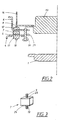
- Fig. 2 which is a cross-section of the invention seen through the elastic element 7, it will become apparent that the element 7 is fitted between the first console part 5 and the second console part 6.
- the console parts 5, 6 comprise through-going holes (not shown), through which are arranged two attachment elements of the element 7, which preferably are screws 9, 10, one upper and one lower.
- the screws 9, 10 are fixed between the console parts 5, 6 by means of two nuts 11, 12, which are screwed onto the screws 9, 10, respectively.
- the airbag console 5, 6 further supports an airbag module 13, which in a conventional manner comprises a gas generator which is arranged to inflate a (not shown) airbag.
- the airbag module 13 is connected, in a known manner, to an acceleration sensor for the detection of a collision-like state. In case of such a state, the gas generator in the airbag module 13 will thus be activated in order to inflate the airbag.
- the airbag module 13 (not shown in Fig. 1) is suspended in such a manner that it rests on the console part 6.
- the airbag module 13 is connected to a console part 14 which is intended to be connected to the console part 6, to be more exact at two attachment points 15, 16.
- the invention comprises an attachment device in the form of a screw 17 with a corresponding nut 18, by means of which the steering wheel console 4 and the first console part 5 can be attached to each other.
- the screw 17 is arranged to extend through (not shown) holes in the console parts 4, 5 and to be fixed by means of the nut 18.
- the airbag module 13 is, preferably in advance, fitted to the console part 14 which in turn is fitted to the console part 6.
- the elastic elements 7, 8 are arranged in advance between the console parts 5, 6.
- the airbag In case of the airbag being triggered, e.g. in case of a collision, the airbag will be inflated in a direction away from the steering wheel. During inflation, the attachment of the airbag module 13 will be affected by heavy forces. In particular, the elastic elements 7, 8 will be affected and stretched.
- the invention is provided with two anchors 19, 20 which are both fixedly attached to the second console part 6 in the immediate vicinity of the elastic elements 7, 8, respectively.
- the number of anchors can vary but preferably four anchors are utilized, of which two anchors 19, 20 can be seen in Fig. 1.
- the anchors 19, 20, respectively comprise an upper cylindrical part which is connected to a lower hat-shaped end part.
- the respective cylindrical parts extend through holes 21, 22 which are made in the first console part 5.
- the holes 21, 22 are somewhat larger than the diameter of the cylindrical part of the anchors 19, 20, respectively.
- the holes 21, 22 are preferably of such a size that during normal operation there is no contact between the holes 21, 22 and the anchors 19, 20.
- the anchors 19, 20 are furthermore screwed onto the second console part 6.
- the hat-shaped end part of the respective anchor 19, 20 are stop elements which prevent the airbag module 12 from being moved more than a predetermined maximal distance in a direction away from the steering wheel hub 1, i.e. the stop element prevents the airbag module from breaking away and moving in a direction upwards according to Fig. 2.
- said predetermined maximal distance exceeds the highest permitted amplitude of vibration of the elements 7, 8, respectively during normal use of the device. If the airbag module 12 has been moved said predetermined distance, this will normally correspond to the elements 7, 8, respectively having been so stretched that they have been so deformed as to be unusable.
- the airbag When triggered, the airbag is furthermore intended to assume a predetermined position relative to a person. In this way, the person can be protected in an optimal manner in case of, for example, a collision.
- the anchors 19, 20 and their corresponding holes 21, 22 serve to guide the airbag during the inflating process.
- the diameter of the holes 21, 22 is somewhat larger than the diameter of the cylindrical parts of the anchors 19, 20.
- the holes 21, 22 are preferably of such a size that contact with the cylindrical parts of the anchors 19, 20 does not occur during normal operation, i.e. when driving and when idling.
- the diameter of the holes 21, 22, respectively is adjusted according to the permitted inclination of the anchors 19, 20, which in turn defines a certain sector relative to the longitudinal axis of the steering wheel axis, within which the airbag can be inflated.
- Fig. 3 shows an elastic element intended to be utilized in connection with the invention.
- the drawing shows an element 7 in the shape of an essentially cubical block, it can also have another shape, e.g. cylindrical.
- the element 7 is preferably made from elastic natural rubber which has energy-absorbing and elastic properties. Alternatively, other kinds of synthetic rubber can be used, for example silicon rubber or the like.
- the rubber block has elastic properties both in the vertical and the horizontal direction. If necessary, the elastic properties in the horizontal directions can be made different from the elastic properties in the vertical direction.
- the element 7 is equipped with an upper washer 23, which is of an essentially square shape, and which serves as an attachment for the upper screw 9.
- the element 7 furthermore comprises a lower washer 24 which serves as an attachment for the lower screw 10.
- the screws 9, 10 are arranged essentially diametrically opposite to each other on the elastic block, thus defining a longitudinal axis along which the airbag module 12 can be moved.
- the airbag module 13 is elastically suspended relative to the rest of the steering wheel device.
- the elastic elements 7, 8 these will, in combination with the rest of the airbag module 13 form a vibration attenuator which reduces vibrations in the rest of the steering wheel system.
- the elements 7, 8 can be shaped so that the airbag module 13 is brought to vibrate in counter-phase to the rest of the steering wheel device at the idling rpm of the engine, which minimizes the vibrations in the steering wheel.
- the elastic elements 7, 8 can be fixed between the console parts 5, 6 (see Fig. 1) by means of gluing or vulcanizing.
- the element 7 is shaped without the screws 9, 10 and without the above described washers 23, 24.
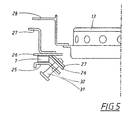
- Fig. 4 shows an alternative embodiment of the present invention.
- the components which correspond to the components shown in Figs. 1-3 have, for reasons of clarity, been given the same reference numerals.
- the embodiment according to Fig. 4 comprises a steering wheel console which extends between two spokes 3, and which in turn comprises a first steering wheel console part 25 and a second steering wheel console part 26. Between the steering wheel console parts 25, 26 there are arranged two elastic elements 7, 8. Furthermore, there is an additional airbag console 27 arranged on top of the second steering wheel console part 26.
- the elastic elements 7, 8 are of a kind which does not comprise any screws for their fitting. Instead, the elements 7, 8 are arranged so that they are fixed between the console parts 25, 26 by means of vulcanizing or a corresponding method.
- the airbag module 13 is fitted to an additional console part 28, which in turn is intended to be attached at two attachment points 29, 30 in the airbag console 27.
- an anchor 31 is arranged for attachment of the airbag console 27 to the steering wheel console part 26, and for guiding the airbag module 13 when its airbag is triggered.
- the anchor 31 is arranged to extend freely through a hole 32 in the first steering wheel console part 25.
- the lower part of the anchor 31 is shaped with a hat-shaped end part with a larger diameter than the rest of the anchor 31.
- the anchor 31 constitutes a stop which limits the movement of the airbag module 13 in the axial direction of the anchor 31.
- the anchor 31 serves to guide the airbag module 13 in a predetermined direction when triggering the airbag, in a manner corresponding to that which has been described above.
- the entire device is fitted as follows: First of all the elastic elements 7, 8 are fitted in advance between the console parts 25, 26.
- the airbag module 13 is attached to the console part 28, which in turn is attached to the airbag console 27.
- the airbag console 27 is fixed to the console part 26 by means of the anchor 31.
- the anchor 31 for this purpose comprises screw and nut elements which are screwed together. Furthermore, the anchor 31 extends through a hole 32 which is made in the console part 25.
- the invention is not limited to the embodiments shown, but can be varied within the scope of the appended claims.
- different kinds of materials and dimensions for the elements 7, 8 can be utilized.
- the invention can in principle be used for the suspension of other mobile devices in the steering wheel hub than an airbag module, for example the horn.
- the elements 7, 8 can be attached in many different manners, e.g. screws and bolts, studs, clips, vulcanizing, gluing or the like.
- the anchors 19, 20 and 31 respectively can be utilized regardless of the presence of elastic elements in order to prevent the airbag module 13 from breaking away from its attachment, and for guiding the airbag in the desired direction.
- the elements 7, 8 are thus not used.
Landscapes
- Engineering & Computer Science (AREA)
- Mechanical Engineering (AREA)
- Air Bags (AREA)
- Steering Controls (AREA)
Claims (11)
- Dispositif pour la suspension d'un module de coussin gonflable (13) par rapport à un dispositif de volant de direction (1) dans un véhicule à moteur par l'intermédiaire d'au moins un élément d'atténuation élastique (7, 8) pour l'atténuation de vibrations, ledit élément d'atténuation (7, 8) comportant un corps de matière élastique qui est fixé sur ledit module de coussin gonflable (13) et qui est fixé sur ledit dispositif de volant de direction (1),
caractérisé en ce que ledit module de coussin gonflable (13) est fixé sur au moins un élément d'ancrage (19, 20; 31) qui s'étend à travers des trous correspondants (21, 22; 32) en liaison avec ledit dispositif de volant de direction (1), les dimensions desdits trous (21, 22; 32) correspondant à une inclinaison prédéterminée de l'élément d'ancrage (19, 20; 31) et servant à guider ledit module de coussin gonflable (13) pour le gonflage dudit coussin gonflable dans une direction prédéterminée. - Dispositif selon la revendication 1, caractérisé en ce que ledit élément d'atténuation (7, 8) est équipé d'un premier élément de fixation (9) qui est fixé sur une partie dudit module de coussin gonflable (13), et d'un deuxième élément de fixation (10) qui est fixé sur une partie dudit dispositif de volant de direction (1).
- Dispositif selon la revendication 1, caractérisé en ce que ledit élément d'atténuation (7, 8) est fixé sur ledit module de coussin gonflable (13) et ledit dispositif de volant de direction (1) au moyen d'un collage ou d'une vulcanisation.
- Dispositif selon l'une quelconque des revendications précédentes, caractérisé en ce que l'élément d'atténuation (7, 8) est disposé entre deux parties de console (5, 6) formant une partie dudit module de coussin gonflable (13).
- Dispositif selon l'une quelconque des revendications 1 à 3, caractérisé en ce que l'élément d'atténuation (7, 8) est disposé entre deux parties de console (25, 26) formant une partie dudit dispositif de volant de direction (1).
- Dispositif selon l'une quelconque des revendications précédentes, caractérisé en ce que les propriétés de la matière de l'élément d'atténuation (7, 8) sont ajustées de telle sorte que ledit module de coussin gonflable (13) vibre essentiellement en opposition de phase avec le dispositif de volant de direction (1) au régime de ralenti du véhiculé à moteur.
- Dispositif selon l'une quelconque des revendications précédentes, caractérisé en ce que l'élément d'atténuation (7, 8) a des propriétés élastiques en mouvement longitudinal comme latéral.
- Dispositif selon l'une quelconque des revendications 2 à 7, caractérisé en ce que lesdits éléments de fixation (19, 20) se composent de vis qui sont disposées essentiellement de manière diamétralement opposée l'une à l'autre sur ledit corps élastique.
- Dispositif selon l'une quelconque des revendications précédentes, caractérisé en ce que ledit élément d'ancrage (19, 20; 31) comporte un élément de butée qui empêche ledit module de coussin gonflable (13) d'être déplacé de plus d'une distance prédéterminée par rapport au dit dispositif de volant de direction (1) pendant le gonflage dudit module de coussin gonflable (13).
- Dispositif selon la revendication 9, caractérisé en ce que ladite distance prédéterminée dépasse l'amplitude possible la plus grande de vibration de l'élément d'atténuation (7, 8) pendant son utilisation normale.
- Dispositif selon l'une quelconque des revendications précédentes, caractérisé en ce que ledit élément d'ancrage (19, 20; 31) s'étend à travers un trou (21, 22; 32) dont les dimensions correspondent à une inclinaison maximale prédéterminée de l'élément d'ancrage (19, 20; 31).
Applications Claiming Priority (3)
| Application Number | Priority Date | Filing Date | Title |
|---|---|---|---|
| SE9602259 | 1996-06-06 | ||
| SE9602259A SE510106C2 (sv) | 1996-06-07 | 1996-06-07 | Anordning för upphängning av en airbagmodul |
| PCT/SE1997/000714 WO1997046424A1 (fr) | 1996-06-06 | 1997-04-29 | Dispositif de fixation |
Publications (2)
| Publication Number | Publication Date |
|---|---|
| EP0901431A1 EP0901431A1 (fr) | 1999-03-17 |
| EP0901431B1 true EP0901431B1 (fr) | 2003-03-12 |
Family
ID=20402924
Family Applications (1)
| Application Number | Title | Priority Date | Filing Date |
|---|---|---|---|
| EP97921066A Expired - Lifetime EP0901431B1 (fr) | 1996-06-06 | 1997-04-29 | Dispositif de fixation |
Country Status (6)
| Country | Link |
|---|---|
| US (1) | US6325411B1 (fr) |
| EP (1) | EP0901431B1 (fr) |
| JP (1) | JP2000511487A (fr) |
| DE (1) | DE69719749T2 (fr) |
| SE (1) | SE510106C2 (fr) |
| WO (1) | WO1997046424A1 (fr) |
Families Citing this family (12)
| Publication number | Priority date | Publication date | Assignee | Title |
|---|---|---|---|---|
| FR2759342B1 (fr) * | 1997-02-07 | 1999-04-30 | Peugeot | Dispositif de liaison elastique entre un sac gonflable et un volant de direction d'un vehicule automobile |
| DE19840998B4 (de) * | 1998-09-08 | 2008-01-24 | Takata-Petri Ag | Airbaganordnung bei Fahrzeugen |
| DE19858691B4 (de) * | 1998-12-18 | 2010-01-07 | Delphi Automotive Systems Deutschland Gmbh | Luftsackmodul für Kraftfahrzeuge |
| DE10156424B4 (de) * | 2000-11-27 | 2016-11-24 | Autoliv Development Ab | Luftsackmodul für Kraftfahrzeuge |
| DE20105434U1 (de) * | 2001-03-28 | 2002-05-16 | TRW Automotive Safety Systems GmbH & Co. KG, 63743 Aschaffenburg | Gassackmodul |
| US6758489B2 (en) * | 2002-10-11 | 2004-07-06 | Key Safety Systems, Inc. | Inflator used as damper for steering wheel |
| US20060061068A1 (en) * | 2004-09-20 | 2006-03-23 | Krista Nash | Dab vibration damper |
| US7144034B2 (en) * | 2004-02-18 | 2006-12-05 | Autoliv Asp, Inc. | Vibration damper gasket |
| WO2006006908A1 (fr) | 2004-07-08 | 2006-01-19 | Andrew Corporation | Station de base radio et son procede de fonctionnement |
| DE202006016948U1 (de) * | 2006-11-06 | 2007-02-01 | Trw Automotive Safety Systems Gmbh | Einstellbare Vorrichtung zur Dämpfung von Schwingungen in einem Lenkrad oder Gassackmodul |
| DE102017114301A1 (de) * | 2017-06-28 | 2019-01-03 | Trw Automotive Safety Systems Gmbh | Schwingungstilgerring sowie gassackmodul mit einem solchen schwingungstilgerring |
| CN116448357A (zh) * | 2022-01-06 | 2023-07-18 | 上汽通用汽车有限公司 | 吸振器开发工装 |
Family Cites Families (8)
| Publication number | Priority date | Publication date | Assignee | Title |
|---|---|---|---|---|
| JPH0545588Y2 (fr) * | 1988-08-08 | 1993-11-22 | ||
| JPH04143143A (ja) * | 1990-10-02 | 1992-05-18 | Nissan Motor Co Ltd | 車両用エアバッグ装置 |
| JP2760248B2 (ja) * | 1992-04-24 | 1998-05-28 | 豊田合成株式会社 | エアバッグ装置を備えたステアリングホイール |
| US5283404A (en) * | 1992-05-27 | 1994-02-01 | Morton International, Inc. | Minimum float, serviceable center blow horn switch in driver side air bag module |
| JPH06270817A (ja) * | 1993-03-23 | 1994-09-27 | Mazda Motor Corp | 自動車のステアリング構造 |
| DE4325250C1 (de) * | 1993-07-28 | 1995-02-16 | Freudenberg Carl Fa | Halter zur schwingungsentkoppelten Befestigung von einem im wesentlichen plattenförmigen Maschinenelement |
| JPH08207783A (ja) * | 1994-12-07 | 1996-08-13 | Toyoda Gosei Co Ltd | ステアリングホイール |
| DE19503816B4 (de) * | 1995-02-06 | 2007-03-22 | Volkswagen Ag | Anordnung zur Befestigung eines aus einem Gehäuseboden und einem Gehäusedeckel bestehenden Gehäuses im Lenkrad |
-
1996
- 1996-06-07 SE SE9602259A patent/SE510106C2/sv unknown
-
1997
- 1997-04-29 EP EP97921066A patent/EP0901431B1/fr not_active Expired - Lifetime
- 1997-04-29 JP JP10500472A patent/JP2000511487A/ja active Pending
- 1997-04-29 DE DE69719749T patent/DE69719749T2/de not_active Expired - Fee Related
- 1997-04-29 US US09/194,851 patent/US6325411B1/en not_active Expired - Fee Related
- 1997-04-29 WO PCT/SE1997/000714 patent/WO1997046424A1/fr not_active Ceased
Also Published As
| Publication number | Publication date |
|---|---|
| SE9602259D0 (sv) | 1996-06-07 |
| SE9602259L (sv) | 1997-12-07 |
| WO1997046424A1 (fr) | 1997-12-11 |
| DE69719749T2 (de) | 2003-12-24 |
| DE69719749D1 (de) | 2003-04-17 |
| SE510106C2 (sv) | 1999-04-19 |
| JP2000511487A (ja) | 2000-09-05 |
| EP0901431A1 (fr) | 1999-03-17 |
| US6325411B1 (en) | 2001-12-04 |
Similar Documents
| Publication | Publication Date | Title |
|---|---|---|
| EP0901431B1 (fr) | Dispositif de fixation | |
| US6296280B1 (en) | Adaptive collapsible steering column | |
| US6435540B1 (en) | Gas inflator for an airbag for reducing vibration in a steering column | |
| US4573724A (en) | Hardbar energy absorbing and vibration damping bumper system damping feature | |
| EP2558348A1 (fr) | Dispositif de vibration pour volant de véhicule | |
| KR102654832B1 (ko) | 차량용 스티어링 휠의 진동 감쇠 구조 및 차량용 스티어링 휠 장치 | |
| US4509781A (en) | Isolated bumper for damping vibrations in vehicles | |
| JP3327297B2 (ja) | 車両の衝撃コントロール構造及び衝撃コントロール方法 | |
| JP4274094B2 (ja) | ステアリングホイール | |
| RU2424133C1 (ru) | Ударозащитное устройство транспортного средства с управляемой системой демпфирования на основе магнитоактивных эластомеров | |
| JPH08258652A (ja) | ガスバッグ衝撃防護システム | |
| JPS6127761A (ja) | 乗物用衝撃吸収ハンドル | |
| KR100792871B1 (ko) | 쉬미 저감형 차량의 조향장치 | |
| JPH08268291A (ja) | 安全操縦ハンドル | |
| KR200228238Y1 (ko) | 도로 시설물용 충격흡수 기둥 | |
| KR100527760B1 (ko) | 에어백장치의 인플레이터 지지구조 | |
| JP2000230605A (ja) | 自動車用パワーユニットの支持装置 | |
| KR200185453Y1 (ko) | 자동차의 현가장치용 부시 | |
| EP1117568B1 (fr) | Systeme de volant pour vehicule | |
| JPH09184525A (ja) | 連結ロッド | |
| JPS6366705B2 (fr) | ||
| KR0183072B1 (ko) | 자동차의 차고 조절장치 | |
| KR20030080479A (ko) | 진동 저감형 차량의 조향휠 | |
| JPH04193649A (ja) | 自動車のステアリングホイール構造 | |
| KR980008845A (ko) | 자동차용 완충장치 |
Legal Events
| Date | Code | Title | Description |
|---|---|---|---|
| PUAI | Public reference made under article 153(3) epc to a published international application that has entered the european phase |
Free format text: ORIGINAL CODE: 0009012 |
|
| 17P | Request for examination filed |
Effective date: 19981202 |
|
| AK | Designated contracting states |
Kind code of ref document: A1 Designated state(s): DE FR GB IT |
|
| 17Q | First examination report despatched |
Effective date: 20010525 |
|
| RAP1 | Party data changed (applicant data changed or rights of an application transferred) |
Owner name: VOLVO CAR CORPORATION |
|
| GRAH | Despatch of communication of intention to grant a patent |
Free format text: ORIGINAL CODE: EPIDOS IGRA |
|
| GRAH | Despatch of communication of intention to grant a patent |
Free format text: ORIGINAL CODE: EPIDOS IGRA |
|
| GRAA | (expected) grant |
Free format text: ORIGINAL CODE: 0009210 |
|
| AK | Designated contracting states |
Designated state(s): DE FR GB IT |
|
| PG25 | Lapsed in a contracting state [announced via postgrant information from national office to epo] |
Ref country code: IT Free format text: LAPSE BECAUSE OF FAILURE TO SUBMIT A TRANSLATION OF THE DESCRIPTION OR TO PAY THE FEE WITHIN THE PRESCRIBED TIME-LIMIT;WARNING: LAPSES OF ITALIAN PATENTS WITH EFFECTIVE DATE BEFORE 2007 MAY HAVE OCCURRED AT ANY TIME BEFORE 2007. THE CORRECT EFFECTIVE DATE MAY BE DIFFERENT FROM THE ONE RECORDED. Effective date: 20030312 Ref country code: FR Free format text: LAPSE BECAUSE OF FAILURE TO SUBMIT A TRANSLATION OF THE DESCRIPTION OR TO PAY THE FEE WITHIN THE PRESCRIBED TIME-LIMIT Effective date: 20030312 |
|
| REG | Reference to a national code |
Ref country code: GB Ref legal event code: FG4D |
|
| REF | Corresponds to: |
Ref document number: 69719749 Country of ref document: DE Date of ref document: 20030417 Kind code of ref document: P |
|
| PLBE | No opposition filed within time limit |
Free format text: ORIGINAL CODE: 0009261 |
|
| STAA | Information on the status of an ep patent application or granted ep patent |
Free format text: STATUS: NO OPPOSITION FILED WITHIN TIME LIMIT |
|
| EN | Fr: translation not filed | ||
| 26N | No opposition filed |
Effective date: 20031215 |
|
| PGFP | Annual fee paid to national office [announced via postgrant information from national office to epo] |
Ref country code: GB Payment date: 20080317 Year of fee payment: 12 |
|
| PGFP | Annual fee paid to national office [announced via postgrant information from national office to epo] |
Ref country code: DE Payment date: 20080430 Year of fee payment: 12 |
|
| GBPC | Gb: european patent ceased through non-payment of renewal fee |
Effective date: 20090429 |
|
| PG25 | Lapsed in a contracting state [announced via postgrant information from national office to epo] |
Ref country code: DE Free format text: LAPSE BECAUSE OF NON-PAYMENT OF DUE FEES Effective date: 20091103 |
|
| PG25 | Lapsed in a contracting state [announced via postgrant information from national office to epo] |
Ref country code: GB Free format text: LAPSE BECAUSE OF NON-PAYMENT OF DUE FEES Effective date: 20090429 |