EP0911187B1 - Luftreifen - Google Patents
Luftreifen Download PDFInfo
- Publication number
- EP0911187B1 EP0911187B1 EP98905838A EP98905838A EP0911187B1 EP 0911187 B1 EP0911187 B1 EP 0911187B1 EP 98905838 A EP98905838 A EP 98905838A EP 98905838 A EP98905838 A EP 98905838A EP 0911187 B1 EP0911187 B1 EP 0911187B1
- Authority
- EP
- European Patent Office
- Prior art keywords
- sipe
- block
- sipes
- depth
- tire
- Prior art date
- Legal status (The legal status is an assumption and is not a legal conclusion. Google has not performed a legal analysis and makes no representation as to the accuracy of the status listed.)
- Expired - Lifetime
Links
- 238000004073 vulcanization Methods 0.000 description 19
- 238000004519 manufacturing process Methods 0.000 description 7
- 238000005336 cracking Methods 0.000 description 6
- 230000015572 biosynthetic process Effects 0.000 description 4
- 238000010276 construction Methods 0.000 description 4
- 230000000694 effects Effects 0.000 description 2
- 239000002344 surface layer Substances 0.000 description 2
- 238000013459 approach Methods 0.000 description 1
- 238000007796 conventional method Methods 0.000 description 1
- 238000005520 cutting process Methods 0.000 description 1
- 230000001934 delay Effects 0.000 description 1
- 239000000463 material Substances 0.000 description 1
- 230000000116 mitigating effect Effects 0.000 description 1
- 230000002265 prevention Effects 0.000 description 1
- XLYOFNOQVPJJNP-UHFFFAOYSA-N water Substances O XLYOFNOQVPJJNP-UHFFFAOYSA-N 0.000 description 1
Images








Classifications
-
- B—PERFORMING OPERATIONS; TRANSPORTING
- B60—VEHICLES IN GENERAL
- B60C—VEHICLE TYRES; TYRE INFLATION; TYRE CHANGING; CONNECTING VALVES TO INFLATABLE ELASTIC BODIES IN GENERAL; DEVICES OR ARRANGEMENTS RELATED TO TYRES
- B60C11/00—Tyre tread bands; Tread patterns; Anti-skid inserts
- B60C11/03—Tread patterns
- B60C11/11—Tread patterns in which the raised area of the pattern consists only of isolated elements, e.g. blocks
-
- B—PERFORMING OPERATIONS; TRANSPORTING
- B60—VEHICLES IN GENERAL
- B60C—VEHICLE TYRES; TYRE INFLATION; TYRE CHANGING; CONNECTING VALVES TO INFLATABLE ELASTIC BODIES IN GENERAL; DEVICES OR ARRANGEMENTS RELATED TO TYRES
- B60C11/00—Tyre tread bands; Tread patterns; Anti-skid inserts
- B60C11/03—Tread patterns
- B60C11/12—Tread patterns characterised by the use of narrow slits or incisions, e.g. sipes
-
- B—PERFORMING OPERATIONS; TRANSPORTING
- B60—VEHICLES IN GENERAL
- B60C—VEHICLE TYRES; TYRE INFLATION; TYRE CHANGING; CONNECTING VALVES TO INFLATABLE ELASTIC BODIES IN GENERAL; DEVICES OR ARRANGEMENTS RELATED TO TYRES
- B60C11/00—Tyre tread bands; Tread patterns; Anti-skid inserts
- B60C11/03—Tread patterns
- B60C11/12—Tread patterns characterised by the use of narrow slits or incisions, e.g. sipes
- B60C11/1259—Depth of the sipe
- B60C11/1263—Depth of the sipe different within the same sipe
-
- B—PERFORMING OPERATIONS; TRANSPORTING
- B60—VEHICLES IN GENERAL
- B60C—VEHICLE TYRES; TYRE INFLATION; TYRE CHANGING; CONNECTING VALVES TO INFLATABLE ELASTIC BODIES IN GENERAL; DEVICES OR ARRANGEMENTS RELATED TO TYRES
- B60C11/00—Tyre tread bands; Tread patterns; Anti-skid inserts
- B60C11/03—Tread patterns
- B60C11/12—Tread patterns characterised by the use of narrow slits or incisions, e.g. sipes
- B60C11/1272—Width of the sipe
- B60C11/1281—Width of the sipe different within the same sipe, i.e. enlarged width portion at sipe bottom or along its length
-
- B—PERFORMING OPERATIONS; TRANSPORTING
- B60—VEHICLES IN GENERAL
- B60C—VEHICLE TYRES; TYRE INFLATION; TYRE CHANGING; CONNECTING VALVES TO INFLATABLE ELASTIC BODIES IN GENERAL; DEVICES OR ARRANGEMENTS RELATED TO TYRES
- B60C11/00—Tyre tread bands; Tread patterns; Anti-skid inserts
- B60C11/03—Tread patterns
- B60C11/13—Tread patterns characterised by the groove cross-section, e.g. for buttressing or preventing stone-trapping
-
- B—PERFORMING OPERATIONS; TRANSPORTING
- B29—WORKING OF PLASTICS; WORKING OF SUBSTANCES IN A PLASTIC STATE IN GENERAL
- B29D—PRODUCING PARTICULAR ARTICLES FROM PLASTICS OR FROM SUBSTANCES IN A PLASTIC STATE
- B29D30/00—Producing pneumatic or solid tyres or parts thereof
- B29D30/06—Pneumatic tyres or parts thereof (e.g. produced by casting, moulding, compression moulding, injection moulding, centrifugal casting)
- B29D30/0601—Vulcanising tyres; Vulcanising presses for tyres
- B29D30/0606—Vulcanising moulds not integral with vulcanising presses
- B29D2030/0607—Constructional features of the moulds
- B29D2030/0613—Means, e.g. sipes or blade-like elements, for forming narrow recesses in the tyres, e.g. cuts or incisions for winter tyres
-
- B—PERFORMING OPERATIONS; TRANSPORTING
- B60—VEHICLES IN GENERAL
- B60C—VEHICLE TYRES; TYRE INFLATION; TYRE CHANGING; CONNECTING VALVES TO INFLATABLE ELASTIC BODIES IN GENERAL; DEVICES OR ARRANGEMENTS RELATED TO TYRES
- B60C11/00—Tyre tread bands; Tread patterns; Anti-skid inserts
- B60C11/03—Tread patterns
- B60C11/12—Tread patterns characterised by the use of narrow slits or incisions, e.g. sipes
- B60C11/1259—Depth of the sipe
- B60C2011/1268—Depth of the sipe being different from sipe to sipe
Definitions
- This invention relates to a pneumatic tire having blocks defined by circumferential grooves formed along a rotating direction of the tire and lateral grooves formed along a widthwise direction of the tire and provided with one-side opened sipes opening to the circumferential grooves in opposite directions to each other, and more particularly aims to avoid dragging of surface rubber or so-called creasing due to delay of rubber flow in the vulcanization building of the tire to prevent the occurrence of flow cracking resulting resulted from the creasing.
- the pneumatic tire having a tread pattern provided with blocks it is general to have a structure wherein a plurality of sipes are formed in the blocks, which particularly ensures the gripping force on wet road surfaces and snow-ice road surfaces as a function thereof.
- the present invention in one aspect provides a pneumatic tire having a tread pattern of blocks (b) defined by circumferential grooves (k) extending along a rotating direction of the tire and lateral grooves (i) extending along a widthwise direction of the tire and having a depth shallower than a depth of the circumferential groove, in which each of the blocks has two or more sipes (S 1 ,S 2 ) having a depth (d) different from the depth of the lateral groove and two sipes among said sipes are a pair of one-side opened sipes alternately opening at their ends to opposed circumferential grooves along substantially the widthwise direction of the tire and having a portion (L) apparently overlapped with each other in the block viewing from a side of the block, characterized in that the pair of the one-side opened sipes (S 1 ,S 2 ) satisfies the following relationship between cross sipe depth (D) and side interval ratio (a/w): D ⁇ (a/w x 50) - 18 where D:
- an overlap length L between the sipes in the block is not less than 10 mm.
- the one-side opened sipes satisfy conditions of 0.42 ⁇ a/w 1 ⁇ 1.0 and 0.42 ⁇ a/w 2 ⁇ 1.0 when the shortest distance between the sipes at the bottom portion of the sipe is a and distances from an edge of the block not opened by the sipe to one of the one-side opened sipes farthest from the edge of the block is w 1 or w 2 .
- sipe interval ratio used herein is defined by a ratio of shortest distance a between mutual sipes at the bottom of the one-side opened sipe at section A-A of the block to distance w in parallel thereto and existing from an edge of the block not opened by the sipe to one of the one-side opened sipes farthest from the edge of the block as diagrammatically shown in Fig. 1 (provided that when w 1 ⁇ w 2 , a smaller value in either of then is adopted).
- cross sipe depth is defined by a distance D between the deepest position of apparently crossing adjoining sipes S 1 , S 2 in a single block b with each other taken from a side view of the block and a position of apparently intersecting a line segment n passing through the deepest position and perpendicular to the surface of the block b with the groove bottom of the lateral grooves sandwiching the block b taken from the side view of the block as shown in Fig. 2 conveniently composing section B-B and section C-C of Fig. 1 (full range r in the embodiment of Fig. 2 has a distance D).
- the shortest distance a between the sipes is a straight distance between mutual flask portions in the case of a flask type sipe and a straight distance between mutual pin portions in the case of a pin type sipe.
- a straight distance from the edge of the block not opened by the sipe to a sipe nearest to the block edge is 20-40% of a length of the block along the block edge, preferably about 30%.
- a flask type sipe or one-side flask type sipe is advantageously adopted as the sipe from a viewpoint of mitigating strain to the bottom of the sipe in the running of the tire.
- a vulcanization mold provided in its inside with blades for the formation of the sipe.
- smooth flowing of rubber is carried out in a position of a vulcanization mold M corresponding to a region A-A of Fig. 3 at both sides of a blade C disposed in the mold M as shown in Fig.
- the sipes S 1 , S 2 have a depth deeper than the groove depth of the lateral groove formed in the widthwise direction of the tire and satisfy the relationship between cross sipe depth D and sipe interval ratio a/w represented by D ⁇ (a/w x 50)-18, so that the rubber flowing between mutual blades C disposed in the vulcanization mold M can be made approximately equal to that of the other zone and hence the occurrence of creasing is avoided.
- the overlap length between mutual adjoining sipes S 1 , S 2 in a plan view is a size L shown in Fig. 8. This value is not less than 10 mm for completely preventing the occurrence of the creasing irrespective of the production conditions and rubber material.
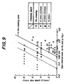
- Fig. 9 shows results examined on the relationship between the cross sipe depth D and the sipe interval ratio a/w with respect to the occurrence of the creasing when the overlap length L between the sipes S 1 , S 2 (tread pattern shown in Fig. 19, sipe shown in Fig. 13) is not less than 10 mm.
- w 1 , w 2 satisfy 0.42 ⁇ a/w 1 ⁇ 1.0 and 0.42 ⁇ a/w 2 ⁇ 1.0, it is clear that there is observed no occurrence of creasing.
- D ⁇ 3 mm as shown in a graph of Fig. 9, when the above condition is satisfied, no occurrence of creasing is observed.
- straight distances L 1 , L 2 from edges e of the block not opened by the sipe to sipes S 1 , S 2 nearest thereto as shown in Fig. 8 are preferably 20-40%, more preferably about 30%, of a side length m of the block opened by the sipe from a viewpoint of ensuring the block rigidity.
- Figs. 11(a) and (b) show a sectional shape of a sipe at its bottom portion, respectively.
- a flask type sipe as shown in Fig. 11(a) or a one-side flask type sipe (one-side pin flask) as shown in Fig. 11(b) is advantageously adaptable.
- the distance a between the mutual sipes can be made somewhat longer than that of a pin flask type sipe as shown at A-A section in Fig. 1 to increase the sipe interval ratio, which is more advantageous in the prevention of the creasing.
- the drainage performance stably maintained but also the edge effect cutting water film can be expected even in the last running stage of the tire (last wearing stage), so that high gripping force on wet road surfaces and ice-snow road surfaces can be ensured.
- the opening directions of the sipes can alternately be opposed every adjoining block along the forward rotating direction of the tire, whereby the block rigidity can be enhanced.
- the sipes as defined in the invention may be formed in a block row existing in a shoulder portion.
- sipe to be formed in the block is straight in the illustrated embodiments of the invention, it may be zigzag. Even in the latter sipe, the effect of preventing the occurrence of creasing resulting in flow cracking is unchangeable.
- Fig. 12 is shown a main part of a pneumatic tire having the sipe structure according to the invention.
- Fig. 13 comprises B-B section and C-C section of sipes S 1 , S 2 shown in Fig. 12 together with a side view conveniently composed thereof at the C-C section.
- this tread pattern has a construction that a step difference t is formed so as to change the groove depth of the lateral groove at both sides of the step difference to increase the rigidity of the block b opened by the sipe at its kicking-out side b K (the kicking-out side of the block easily opens the sipe and the groove depth of r the lateral groove corresponding to such a side is shallower to increase the rigidity and the subsequent groove depth of the lateral groove bordered by the step difference t is deeper to balance the shallower portion) and also the depth of the sipe is changed along the lateral groove (a slant portion S K is formed) to prevent chipping of the block.
- the cross sipe depth D is a distance between a deepest position h of apparently crossing the sipes S1, S2 taken in a side view and a position i of apparently intersecting a line segment n passing through the position h and perpendicular to the outer surface of the block with groove bottoms of the lateral grooves sandwiching the block b therebetween as shown in Fig. 13.
- the slant portion S k is formed between a cut edge S a of the sipe S 1 , S 2 and the bottom portion thereof to connect them, whereby the block chipping can be prevented and also it is possible to make the value of the cross sipe depth D smaller than that of a sipe having a flat bottom portion as shown in Fig. 2 (called a flat sipe), which can advantageously enlarge the no-creasing zone shown in relation to the sipe interval ratio in Fig. 9. Furthermore, such a sipe tends to smoothen the flowing of rubber at an initial stage in the vulcanization building of the tire.
- the shape of the slant portion S k may be straight or curved. Also, the forming zone of the slant portion may be a region directly ranging from a cut end of the sipe along the bottom portion to an opening end of the sipe.
- Figs. 14-17 are shown main parts of a blade C for the formation of the sipe and a projection j for the formation of the circumferential groove disposed inside of a mold M suitable for the manufacture of the pneumatic tire according to the invention, respectively.
- the sipe is a flask type sipe (pin flask, flask, one-side flask or the like)
- an expanding portion C 1 capable of forming the flask is disposed on a top end portion of the blade C.
- Fig. 18 shows an example wherein the depth of the sipe S 1 , S 2 is shallower than that of the lateral groove, which is included in the invention.
- the cross sipe depth D is conveniently adopted to be zero.
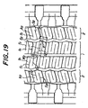
- Fig. 19 shows a tread pattern applied to a pneumatic tire (a heavy duty pneumatic tire having a size of 11R22.5) with a sipe structure according to the invention having sipes as shown in Fig. 2 (flat sipes).
- Fig. 20 shows an embodiment of the pneumatic tire having the same structure as in Fig. 19 except that a step difference t is formed in the lateral groove of the tire for increasing the rigidity of the block at a kicking-out side and groove depths at both sides of the step difference are 10 mm and 15 mm and the cross sipe depth D is 7 mm. Even in this pneumatic tire, it is possible to smoothen the rubber flowing from a lower side of a blade in a mold during the vulcanization building and the occurrence of creasing resulting in flow cracking is not observed.
- Fig. 21 and Fig. 22 are shown other tread patterns of the pneumatic tire according to the invention (tire size: 11R22.5) having a step difference t in the lateral groove and sipes with a shape and a size as shown in Fig. 23, respectively.
- a/w 1 and a/w 2 are 0.428
- L is 12 mm
- the cross sipe depth D is mm.
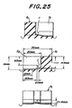
- Fig. 24 is shown a pneumatic tire in which a cut length P in the central zone 1 of the tread is 20 mm, a is 8 mm, w 1 and w 2 are 24 mm, a/w 1 and a/w 2 are 0.333, L is 8 mm, sipes S1, S2 have a shape and a size as shown in Fig. 25 and the side zone 2 of the tread is the same as in Figs. 21 and 22. Even in this tire, the rubber flowing is smooth at a position corresponding to the blade of the mold in the vulcanization building and the occurrence of creasing resulting in flow cracking is not observed.
- Fig. 26 is shown a tread pattern applied to a pneumatic tire having lateral grooves with a step difference t (heavy duty pneumatic tire having a size of 11R22.5).
- the rubber flowing is smooth from the lower portion of the blade of the mold in the vulcanization building, and the uneven wear can be improved without causing creasing resulting in flow cracking.
- the rubber flowing is smoothly conducted in the mold during the vulcanization building, so that there can be prevented the occurrence of creasing, which has been a problem in the manufacture of a pneumatic tire provided with at least a pair of one-side opened sipes alternately opening at their ends to opposed circumferential grooves.
Landscapes
- Engineering & Computer Science (AREA)
- Mechanical Engineering (AREA)
- Tires In General (AREA)
- Moulds For Moulding Plastics Or The Like (AREA)
Claims (7)
- Luftreifen mit einem Laufflächenmuster aus Blöcken (b), die durch Umfangsrillen (k), die sich entlang einer Drehungsrichtung des Reifens erstrecken, und seitliche Rillen (i) definiert werden, die sich entlang einer Breitenrichtung des Reifens erstrecken und eine Tiefe aufweisen, die flacher ist als eine Tiefe der Umfangsrille, wobei jeder der Blöcke zwei oder mehrere Lamellen (S1, S2) mit einer Tiefe (d) aufweist, die von der Tiefe der seitlichen Rille abweichend ist, und wobei zwei Lamellen unter den Lamellen ein Paar von einseitig geöffneten Lamellen sind, die sich abwechselnd an ihren Enden zu den gegenüberliegenden Umfangsrillen entlang im wesentlichen der Breitenrichtung des Reifens öffnen und einen Abschnitt (L) aufweisen, der sich offensichtlich miteinander im Block überdeckt, von einer Seite des Blockes aus betrachtet, dadurch gekennzeichnet, daß das Paar von einseitig geöffneten Lamellen (S1, S2) die folgende Beziehung zwischen der Querlamellentiefe (D) und dem Lamellenabstandsverhältnis (a/w) erfüllt:und ein schräger Abschnitt (Sk), der die Lamellentiefe entlang der seitlichen Rille verändert, wird zwischen einer Schnittkante (Sa) der Lamelle (S1, S2) und dem Bodenabschnitt davon gebildet, um sie zu verbinden.D: ein Abstand von der tiefsten Position in der Überkreuzung des Paares der Lamellen (S1, S2), in einem offensichtlichen überdeckten Zustand in einer Seitenansicht eines einzelnen Blockes (b) betrachtet, bis zu einer Schnittposition zwischen einer Strecke (n), die durch die tiefste Position hindurchgeht und senkrecht zur Oberfläche des Blockes, und wobei der Rillenboden der seitlichen Rillen (i) offensichtlich den Block in der Seitenansicht des Blockes dazwischen anordnet;a: der kürzeste Abstand zwischen dem Paar der Lamellen am Boden der einseitig geöffneten Lamelle;w: der weiteste Abstand parallel zum kürzesten Abstand (a) und zwischen einem Rand des Blockes, der nicht durch die Lamelle geöffnet wird, und der einseitig geöffneten Lamelle, vorausgesetzt, daß, wenn w1 nicht gleich w2 ist, dann ein kleinerer Wert bei beiden von ihnen angenommen wird;
- Luftreifen mit einem Laufflächenmuster aus Blöcken (b), die durch Umfangsrillen (k), die sich entlang einer Drehungsrichtung des Reifens erstrecken, und seitliche Rillen (i) definiert werden, die sich entlang einer Breitenrichtung des Reifens erstrecken und eine Tiefe aufweisen, die flacher ist als eine Tiefe der Umfangsrille, wobei jeder der Blöcke zwei oder mehrere Lamellen (S1, S2) mit einer Tiefe aufweist, die von der Tiefe der seitlichen Rille abweichend ist, und wobei zwei Lamellen unter den Lamellen ein Paar von einseitig geöffneten Lamellen sind, die sich abwechselnd an ihren Enden zu den gegenüberliegenden Umfangsrillen entlang im wesentlichen der Breitenrichtung des Reifens öffnen und einen Abschnitt (L) aufweisen, der sich offensichtlich miteinander im Block überdeckt, von einer Seite des Blockes aus betrachtet, dadurch gekennzeichnet, daß das Paar von einseitig geöffneten Lamellen (S1, S2) die folgende Beziehung zwischen der Querlamellentiefe (D) und dem Lamellenabstandsverhältnis (a/w) erfüllt:wobei das Paar Lamellen (S1, S2) eine Tiefe aufweist, die tiefer ist als die Tiefe der seitlichen Rille.D: ein Abstand von der tiefsten Position in der Überkreuzung des Paares der Lamellen (S1, S2), in einem offensichtlichen überdeckten Zustand in einer Seitenansicht eines einzelnen Blockes (b) betrachtet, bis zu einer Schnittposition zwischen einer Strecke (n), die durch die tiefste Position hindurchgeht und senkrecht zur Oberfläche des Blockes, und wobei der Rillenboden der seitlichen Rillen (i) offensichtlich dazwischen den Block in der Seitenansicht des Blockes dazwischen anordnet;a: der kürzeste Abstand zwischen dem Paar der Lamellen am Boden der einseitig geöffneten Lamelle;w: der weiteste Abstand parallel zum kürzesten Abstand (a) und zwischen einem Rand des Blockes, der nicht durch die Lamelle geöffnet wird, und der einseitig geöffneten Lamelle, vorausgesetzt, daß, wenn w1 nicht gleich w2 ist, dann ein kleinerer Wert bei beiden von ihnen angenommen wird;
- Luftreifen nach Anspruch 1 oder 2, dadurch gekennzeichnet, daß die Überdeckungslänge (L) zwischen den Lamellen (S1, S2) im Block (b) nicht kleiner ist als 10mm.
- Luftreifen nach Anspruch 3, dadurch gekennzeichnet, daß, wenn die Querlamellentiefe (D) nicht größer ist als 3 mm, die einseitig geöffneten Lamellen (S1, S2) die folgenden Bedingungen erfüllen, wenn der kürzeste Abstand zwischen den Lamellen am Bodenabschnitt der Lamelle (a) beträgt und die Abstände von einem Rand des Blockes, der nicht durch die Lamelle geöffnet wird, zu einem der einseitig geöffneten Lamellen am weitesten vom Rand des Blockes w1 oder w2 beträgt:
- Luftreifen nach einem der Ansprüche 1 bis 4, dadurch gekennzeichnet, daß ein geradliniger Abstand (L1, L2) vom Rand (e) des Blockes (b), der nicht durch die Lamelle geöffnet ist, zu einer Lamelle (S2, S1), die dem Blockrand am nächsten ist, 20 bis 40% einer Länge (m) des Blockes entlang des Blockrandes beträgt.
- Luftreifen nach einem der Ansprüche 1 bis 5, dadurch gekennzeichnet, daß die Lamelle (S1, S2) eine flaschenartige Lamelle ist.
- Luftreifen nach einem der Ansprüche 1 bis 5, dadurch gekennzeichnet, daß die Lamelle (S1, S2) eine einseitige flaschenartige Lamelle ist.
Applications Claiming Priority (7)
| Application Number | Priority Date | Filing Date | Title |
|---|---|---|---|
| JP5612597 | 1997-03-11 | ||
| JP5612597 | 1997-03-11 | ||
| JP56125/97 | 1997-03-11 | ||
| JP923098 | 1998-01-21 | ||
| JP9230/98 | 1998-01-21 | ||
| JP923098 | 1998-01-21 | ||
| PCT/JP1998/000988 WO1998040228A1 (en) | 1997-03-11 | 1998-03-10 | Pneumatic tire |
Publications (3)
| Publication Number | Publication Date |
|---|---|
| EP0911187A1 EP0911187A1 (de) | 1999-04-28 |
| EP0911187A4 EP0911187A4 (de) | 2000-07-05 |
| EP0911187B1 true EP0911187B1 (de) | 2004-08-18 |
Family
ID=26343909
Family Applications (1)
| Application Number | Title | Priority Date | Filing Date |
|---|---|---|---|
| EP98905838A Expired - Lifetime EP0911187B1 (de) | 1997-03-11 | 1998-03-10 | Luftreifen |
Country Status (3)
| Country | Link |
|---|---|
| EP (1) | EP0911187B1 (de) |
| DE (1) | DE69825696T2 (de) |
| WO (1) | WO1998040228A1 (de) |
Families Citing this family (11)
| Publication number | Priority date | Publication date | Assignee | Title |
|---|---|---|---|---|
| FI115833B (fi) | 2000-05-23 | 2005-07-29 | Nokian Renkaat Oyj | Kuviopalat ajoneuvon renkaan kulutuspinnassa |
| WO2002038399A2 (fr) | 2000-11-13 | 2002-05-16 | Societe De Technologie Michelin | Bande de roulement de pneumatique et element moulant de moule d'une telle bande |
| JP2006069440A (ja) * | 2004-09-03 | 2006-03-16 | Bridgestone Corp | 空気入りタイヤ |
| US20090095387A1 (en) | 2007-10-15 | 2009-04-16 | The Goodyear Tire & Rubber Co. | Tire With Tread Having Full Depth Siping |
| JP5181934B2 (ja) * | 2008-08-29 | 2013-04-10 | 横浜ゴム株式会社 | 空気入りタイヤ |
| US20110284141A1 (en) * | 2010-05-21 | 2011-11-24 | Continental Tire North America, Inc. | Rotating Sipe |
| FR2984797B1 (fr) * | 2011-12-22 | 2014-02-21 | Michelin Soc Tech | Element moulant comportant des moyens de decoupe pour le moulage et la vulcanisation d'une bande de roulement d'un pneumatique |
| JP6077934B2 (ja) * | 2013-05-27 | 2017-02-08 | 住友ゴム工業株式会社 | 空気入りタイヤ |
| JP7081185B2 (ja) * | 2018-02-05 | 2022-06-07 | 住友ゴム工業株式会社 | タイヤ |
| JP7581719B2 (ja) * | 2020-09-15 | 2024-11-13 | 住友ゴム工業株式会社 | タイヤ |
| DE102022204222A1 (de) * | 2022-04-29 | 2023-11-02 | Continental Reifen Deutschland Gmbh | Fahrzeugreifen |
Family Cites Families (8)
| Publication number | Priority date | Publication date | Assignee | Title |
|---|---|---|---|---|
| JP2890310B2 (ja) * | 1989-01-30 | 1999-05-10 | 横浜ゴム株式会社 | 空気入りラジアルタイヤ |
| JP3208417B2 (ja) * | 1991-11-11 | 2001-09-10 | 株式会社ブリヂストン | 空気入りタイヤ |
| JP3583483B2 (ja) * | 1993-11-18 | 2004-11-04 | 株式会社ブリヂストン | 空気入りタイヤ |
| JPH07172111A (ja) * | 1993-12-21 | 1995-07-11 | Bridgestone Corp | 重荷重用空気入りタイヤ |
| JP2804710B2 (ja) * | 1993-12-28 | 1998-09-30 | 住友ゴム工業株式会社 | 空気入りタイヤ |
| JP3581203B2 (ja) * | 1995-12-06 | 2004-10-27 | 株式会社ブリヂストン | 重荷重用空気入りタイヤ |
| JP3499995B2 (ja) * | 1995-12-29 | 2004-02-23 | 住友ゴム工業株式会社 | 空気入りタイヤ |
| JP3694082B2 (ja) * | 1996-01-25 | 2005-09-14 | 株式会社ブリヂストン | 空気入りタイヤ |
-
1998
- 1998-03-10 EP EP98905838A patent/EP0911187B1/de not_active Expired - Lifetime
- 1998-03-10 WO PCT/JP1998/000988 patent/WO1998040228A1/ja not_active Ceased
- 1998-03-10 DE DE69825696T patent/DE69825696T2/de not_active Expired - Fee Related
Also Published As
| Publication number | Publication date |
|---|---|
| EP0911187A1 (de) | 1999-04-28 |
| DE69825696D1 (de) | 2004-09-23 |
| EP0911187A4 (de) | 2000-07-05 |
| WO1998040228A1 (en) | 1998-09-17 |
| DE69825696T2 (de) | 2005-08-18 |
Similar Documents
| Publication | Publication Date | Title |
|---|---|---|
| JP4711373B2 (ja) | 空気入りタイヤ | |
| US20080029193A1 (en) | Tire Tread Comprising Zigzag Incisions And Blades For Molding Such Incisions | |
| US12138963B2 (en) | Winter tyre | |
| EP0911187B1 (de) | Luftreifen | |
| JPH11321240A (ja) | 冬用タイヤのトレッドパターン | |
| US10179482B2 (en) | Pneumatic tire | |
| KR20100090640A (ko) | 중하중용 타이어 | |
| GB2250488A (en) | Pneumatic vehicle tyre tread pattern | |
| CN109070647B (zh) | 充气轮胎 | |
| US20130068359A1 (en) | Pneumatic tire | |
| US6874552B2 (en) | Tread having offset first and second incisions | |
| JPH0310910A (ja) | 重荷重用空気入りタイヤ | |
| JPH06171316A (ja) | 重荷重用空気入りラジアルタイヤ | |
| JPH0624212A (ja) | タイヤのトレッド構造 | |
| US20170066291A1 (en) | Tire | |
| JP2003182314A (ja) | 空気入りタイヤ | |
| CN107921824B (zh) | 充气轮胎 | |
| WO2015156397A1 (ja) | タイヤ用トレッド及びタイヤ | |
| JP4986384B2 (ja) | 空気入りタイヤとその製造方法 | |
| JP2005088670A (ja) | 空気入りタイヤ | |
| CN211684524U (zh) | 一种雪地轮胎花纹 | |
| JP3626300B2 (ja) | 空気入りタイヤ | |
| JPH10226207A (ja) | 空気入りタイヤ | |
| WO2016199774A1 (ja) | タイヤ | |
| JPH05338415A (ja) | 空気入りタイヤ |
Legal Events
| Date | Code | Title | Description |
|---|---|---|---|
| PUAI | Public reference made under article 153(3) epc to a published international application that has entered the european phase |
Free format text: ORIGINAL CODE: 0009012 |
|
| 17P | Request for examination filed |
Effective date: 19981103 |
|
| AK | Designated contracting states |
Kind code of ref document: A1 Designated state(s): DE FI FR GB SE |
|
| A4 | Supplementary search report drawn up and despatched |
Effective date: 20000524 |
|
| AK | Designated contracting states |
Kind code of ref document: A4 Designated state(s): DE FI FR GB SE |
|
| 17Q | First examination report despatched |
Effective date: 20020416 |
|
| GRAP | Despatch of communication of intention to grant a patent |
Free format text: ORIGINAL CODE: EPIDOSNIGR1 |
|
| GRAS | Grant fee paid |
Free format text: ORIGINAL CODE: EPIDOSNIGR3 |
|
| GRAA | (expected) grant |
Free format text: ORIGINAL CODE: 0009210 |
|
| AK | Designated contracting states |
Kind code of ref document: B1 Designated state(s): DE FI FR GB SE |
|
| REG | Reference to a national code |
Ref country code: GB Ref legal event code: FG4D |
|
| REG | Reference to a national code |
Ref country code: SE Ref legal event code: TRGR |
|
| REF | Corresponds to: |
Ref document number: 69825696 Country of ref document: DE Date of ref document: 20040923 Kind code of ref document: P |
|
| PG25 | Lapsed in a contracting state [announced via postgrant information from national office to epo] |
Ref country code: GB Free format text: LAPSE BECAUSE OF NON-PAYMENT OF DUE FEES Effective date: 20050310 Ref country code: FI Free format text: LAPSE BECAUSE OF NON-PAYMENT OF DUE FEES Effective date: 20050310 |
|
| PG25 | Lapsed in a contracting state [announced via postgrant information from national office to epo] |
Ref country code: SE Free format text: LAPSE BECAUSE OF NON-PAYMENT OF DUE FEES Effective date: 20050311 |
|
| ET | Fr: translation filed | ||
| PLBE | No opposition filed within time limit |
Free format text: ORIGINAL CODE: 0009261 |
|
| STAA | Information on the status of an ep patent application or granted ep patent |
Free format text: STATUS: NO OPPOSITION FILED WITHIN TIME LIMIT |
|
| 26N | No opposition filed |
Effective date: 20050519 |
|
| PG25 | Lapsed in a contracting state [announced via postgrant information from national office to epo] |
Ref country code: DE Free format text: LAPSE BECAUSE OF NON-PAYMENT OF DUE FEES Effective date: 20051001 |
|
| EUG | Se: european patent has lapsed | ||
| GBPC | Gb: european patent ceased through non-payment of renewal fee |
Effective date: 20050310 |
|
| PG25 | Lapsed in a contracting state [announced via postgrant information from national office to epo] |
Ref country code: FR Free format text: LAPSE BECAUSE OF NON-PAYMENT OF DUE FEES Effective date: 20051130 |
|
| REG | Reference to a national code |
Ref country code: FR Ref legal event code: ST Effective date: 20051130 |