EP0913216B1 - Kettenartige Stranggusskokille - Google Patents
Kettenartige Stranggusskokille Download PDFInfo
- Publication number
- EP0913216B1 EP0913216B1 EP98203568A EP98203568A EP0913216B1 EP 0913216 B1 EP0913216 B1 EP 0913216B1 EP 98203568 A EP98203568 A EP 98203568A EP 98203568 A EP98203568 A EP 98203568A EP 0913216 B1 EP0913216 B1 EP 0913216B1
- Authority
- EP
- European Patent Office
- Prior art keywords
- elements
- chains
- ingot mold
- molding
- engaging
- Prior art date
- Legal status (The legal status is an assumption and is not a legal conclusion. Google has not performed a legal analysis and makes no representation as to the accuracy of the status listed.)
- Expired - Lifetime
Links
- 238000009749 continuous casting Methods 0.000 title claims description 13
- 238000000465 moulding Methods 0.000 claims abstract description 68
- 239000002184 metal Substances 0.000 claims abstract description 8
- 229910052751 metal Inorganic materials 0.000 claims abstract description 8
- 230000008878 coupling Effects 0.000 claims description 3
- 238000010168 coupling process Methods 0.000 claims description 3
- 238000005859 coupling reaction Methods 0.000 claims description 3
- 238000007493 shaping process Methods 0.000 abstract 1
- 238000000034 method Methods 0.000 description 5
- 230000008569 process Effects 0.000 description 5
- 238000005266 casting Methods 0.000 description 4
- 230000008901 benefit Effects 0.000 description 2
- 230000000295 complement effect Effects 0.000 description 2
- 238000001816 cooling Methods 0.000 description 2
- 230000017525 heat dissipation Effects 0.000 description 2
- 229910001338 liquidmetal Inorganic materials 0.000 description 2
- 238000004519 manufacturing process Methods 0.000 description 2
- 238000005058 metal casting Methods 0.000 description 2
- 230000010355 oscillation Effects 0.000 description 2
- RYGMFSIKBFXOCR-UHFFFAOYSA-N Copper Chemical group [Cu] RYGMFSIKBFXOCR-UHFFFAOYSA-N 0.000 description 1
- 229910000831 Steel Inorganic materials 0.000 description 1
- 230000009471 action Effects 0.000 description 1
- 230000005540 biological transmission Effects 0.000 description 1
- 239000002131 composite material Substances 0.000 description 1
- 238000012423 maintenance Methods 0.000 description 1
- 238000002844 melting Methods 0.000 description 1
- 230000008018 melting Effects 0.000 description 1
- 230000009467 reduction Effects 0.000 description 1
- 230000008439 repair process Effects 0.000 description 1
- 230000000630 rising effect Effects 0.000 description 1
- 238000005096 rolling process Methods 0.000 description 1
- 238000000926 separation method Methods 0.000 description 1
- 239000010959 steel Substances 0.000 description 1
Images





Classifications
-
- B—PERFORMING OPERATIONS; TRANSPORTING
- B22—CASTING; POWDER METALLURGY
- B22D—CASTING OF METALS; CASTING OF OTHER SUBSTANCES BY THE SAME PROCESSES OR DEVICES
- B22D11/00—Continuous casting of metals, i.e. casting in indefinite lengths
- B22D11/06—Continuous casting of metals, i.e. casting in indefinite lengths into moulds with travelling walls, e.g. with rolls, plates, belts, caterpillars
- B22D11/0637—Accessories therefor
- B22D11/0648—Casting surfaces
- B22D11/0657—Caterpillars
Definitions
- This invention refers to an sliding chain-type ingot mold for a continuous casting plant.
- this system allows considerably boosting the casting speed, so as to attain the same productivity of three or four of the parallel lines described above. This also achieves the notable advantage of making it possible to operate directly in line with a subsequent rolling train or similar.
- This type of continuous casting process simply known as a sliding chain-type ingot mold, provides in particular, as mentioned, for two chains arranged in a closed ring, each carrying a multiple number of molding elements.
- the molding elements can be made to interface with each other, so as to form a closed mold in the straight portion of the chain.
- a chain carries molding elements that are in one of their terminal portions capable of interlocking with the terminal portion of the molding elements carried by another chain. This produces a length of continuous cavity, formed in its interior by the interfacing and associated molds, in which the molten metal coming from the trays is cast.
- the deformations mainly cause a detachment of the two portions of the mold interfacing and associated with each other to form the cavity, with a resulting leakage of molten metal.
- EP-A-0 791 417 relates to a mould of the type caterpillar for a continuous casting machine.
- US-A-4 770 228 refers to a metal casting device equipped with a continuously rotating supporting element.
- the main purpose of this invention is to solve the technical problems affecting the mentioned known art in an extremely simple, economical and particularly functional manner, while also eliminating the drawbacks outlined above.
- Another purpose is to reduce to a minimum the wear of the parts involved and in reciprocal contact during the continuous casting process.
- FIGS. 1 and 2 show two continuous casting plants, one of a vertical and the other of a horizontal type, both equipped with a sliding chain-type ingot mold according to this invention.
- the figures show a basket 10 feeding a dragging chain-type ingot mold, indicated in its overall form by 11.
- the ingot mold 11 comprises two pairs of chains 12 and 13, both arranged in a closed ring, rotating in opposite directions and carrying a multiple number of molding or shell-type elements 14 and 15.
- the molding or shell-type elements 14 and 15, forming two half-molds can be made to interface with each other so as to form a closed mold.
- the two half molds are capable, when engaged with each other, of forming a cavity for the casting of metal.
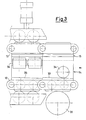
- the ingot mold 11 is in fact designed so that the two pairs of chains 12 and 13 are made to wind up on sprockets 16 and 17 which, in addition to causing the chains' forward motion, also define a straight portion of the ingot mold in which the two opposing half molds engage with each other so as to interlock and form a continuous cavity.
- a pair of chains 13 carries some molding elements 15 fitted in a terminal portion with external surfaces 19 capable of inserting and engaging themselves in corresponding internal surfaces 18 of a terminal portion of the half-mold elements 14 carried by the other pair of chains 12.
- the pair of chains 13 is arranged to the sides of the base portion 21, just as the pair of chains 12 is arranged to the sides of the base portion 20.
- the base portion carries two lateral extensions 26, fitted with a hollow seat 27 housing a rod which also passes through a hole 29 in the base portion 20.
- This arrangement produces a connecting element designed to maintain a firm bond between the two portions 14a and 14b, -which constitute each molding element 14 of the embodiment shown. It can in particular be noted that these two portions 14a and 14b are coupled along opposing, rounded and complementary surfaces 30, around which the two portions 14a and 14b of the molding element 14 may oscillate in the way of a spherical coupling working in combination with an underlying barrel-shaped roller 39.
- the two molding elements 14 and 15 offer a symmetric shape with respect to an axis of symmetry 38 perpendicular to the two base portions 20 and 21.
- the upper surfaces of the two lateral extensions 26 of the base portion 20 are further equipped with two cam-shaped surfaces 33. These cam-shaped surfaces are capable of contacting and interacting with some engaging elements constituted by a pair of rollers 34 in a fixed frame 35 at the extreme end of the straight portion of the ingot mold.
- the cam-shaped surfaces 33 are arranged along the longitudinal direction of motion of the two pairs of chains, and increase in height in the direction of their forward motion.
- the straight portion of the ingot mold may provide for some rollers 36, which are always firmly attached to the fixed frame 35. These rollers 36, which are positioned from opposite sides on the external surfaces of the leg-shaped walls 22, 24 of the molding elements 14, form a lateral guide, thanks also to the presence of springs 37 capable of modulating their lateral pushing action.
- both sets of multiple molding elements 14 and 15 are equipped with their relative cooling facilities (not shown) as well as with some guiding elements along their entire path.
- Some drive units rotate the two pairs of chains 12 and 13 along with their respective molding elements 14 and 15.
- the cavity is kept in a continuous and uniform condition also thanks to the presence of the rollers 36 acting on the external surfaces of the leg-shaped walls 22, 24 of the molding elements 14.
- This rotation also helps to prevent friction between the mentioned surfaces, and any undesirable deformations on the two molding elements.
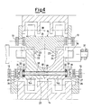
- Figures 7 and 8 show a simplified alternative first embodiment of molding elements capable of being positioned on the pairs of chains while using various means of engagement.
- the molding elements are generally produced, as shown before, one in a single piece and the other in two pieces.
- equal elements are designated by the same reference numbers as formerly used, preceded by the number "1".
- Each lower molding element 114 is in fact produced in two portions, indicated by 114a and 114b, and presents an asymmetrical shape with respect to an axis 138 set perpendicular to two base portions 120 and 121.
- Figure 7 shows a first transversal cross section where it can be seen that in the molding element 114 the base portion 120 constitutes the first portion 114a, which is fitted on one side with a pointed leg-type wall 122.
- the other side carries a rounded surface 130 facing a complementary rounded surface 130 of the second portion 114b.
- This second portion 114b extends on the other side into a vertical leg-type wall 124, similar to the previous walls 24, but arranged to the side of the upper base portion 121.
- the molding section 115 is simply constituted by a molding element rather similar to the molding element 114, but is rotated in its arrangement by 180° with respect to the mentioned axis 138 of the mold, and produced from a single piece.
- leg-shaped wall 124 of the upper molding element 115 are set against the external surfaces 118 of the pointed leg-shaped wall 122 of the lower molding element 114, and the same applies on the other side to the same leg-shaped walls 124 and 122.
- the three pressurizing rollers 136 form lateral guides and a fixed lower roller 140.
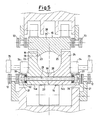
- a second cross section in Figure 8 shows that there are two fixed upper and lower rollers 139 acting to counter the motion.
- the pressurizing rollers 134 act as external engaging elements.
- This arrangement of the rollers promotes the detachment between the two molding elements 114 and 115, for example by forcibly oscillating the portion 114b around the rounded surfaces 130 and the upper molding element with respect to the fixed upper roller 139.
- An arrangement based on an inclined rod 127 passing through some hollow seats 127 produces a connecting element designed to keep the two portions 114a and 114b tied up to each other even during the oscillation.
- the molding elements 114 and 115 are both produced from a single piece, and there is no pair of rounded surfaces 130.
- both the lower molding element 114 and the upper molding element 115 oscillate with respect to the two fixed lower and upper rollers 139, whenever the two upper and lower pressurizing rollers 134 act on the cam-type surface 133, if available, or by shifting the pressurizing rollers 134 with the aid of an appropriate actuator.
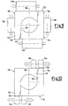
- Figures 11 and 12 finally show a fourth alternative embodiment of some molding elements capable of being positioned on the pairs of chains.
- both molding elements are produced from a single piece, and equal elements are indicated by the same reference numbers preceded by the number "2".
- a lower molding element 214 is produced from a single piece and presents an asymmetrical shape with respect to an axis 238 perpendicular to the two base portions 220 and 221.
- the upper molding element 215 is simply constituted by a molding element entirely similar to the lower molding element 214, but rotated in its arrangement by 180° with respect to the axis 238.
- a second cross section in Figure 12 shows that there are two fixed lateral rollers 239 acting to counter the motion, and two further pressurizing rollers 234 acting on the opposing lateral cam-shaped surfaces 233 of the two molding elements 214 and 215, again if available, or being shifted by appropriate actuators not shown here.
- the pressurizing rollers 234 act as external engaging elements.
Landscapes
- Engineering & Computer Science (AREA)
- Mechanical Engineering (AREA)
- Continuous Casting (AREA)
- Mold Materials And Core Materials (AREA)
- Molds, Cores, And Manufacturing Methods Thereof (AREA)
- Moulds, Cores, Or Mandrels (AREA)
- Metal Rolling (AREA)
- Pinball Game Machines (AREA)
Claims (11)
- Blockform vom Gleitkettentyp für eine kontinuierliche Gussanlage mit zwei Paaren von Ketten (12, 13), die beide in einem System mit geschlossenem Ring angeordnet sind und sich in entgegengesetzten Richtungen drehen, wobei jedes Paar von Ketten (12, 13) eine Anzahl von Elementen (14, 15; 114, 115; 214, 215) vom Form- oder Schalentyp trägt, die zwei Halbformen darstellen, die so ausgebildet sind, um miteinander verbunden werden zu können und damit eine geschlossene Form herzustellen und einen Hohlraum zur Aufnahme von geschmolzenem Metall zu erzeugen, wobei die Paare von Ketten (12, 13) so angeordnet sind, um auf Kettenräder (16, 17) aufgewickelt werden zu können, während ein gerader Abschnitt zwischen diesen beschrieben wird, und wobei ein Paar von Ketten (13) Formelemente (15, 115, 215) trägt, die in ihren Anschlussabschnitten bestimmte Flächen (19, 119, 219) vorsehen, die in der Lage sind, mit den gegenüberliegenden Oberflächen (18, 118, 218) eines Anschlussabschnittes einiger Halbformelemente (14, 114, 214) in Eingriff zu treten, die durch das andere Paar von Ketten (12) getragen werden, um den Hohlraum zu formen, dadurch gekennzeichnet, dass bestimmte Eingriffselemente (34, 134, 234) vorgesehen sind, die mit nockenförmigen Oberflächen (33, 133, 233) wechselwirken können, die auf einer Seite an zumindest einem (14, 114, 214) der Formelemente und auf der anderen Seite an einem fixierten Rahmen (35) vorgesehen sind, der so ausgebildet ist, um die Oberflächen (18, 19; 118, 119; 218, 219) zu trennen und anzunähern, die an dem Ende des geraden Abschnittes miteinander in Eingriff stehen; und dass zumindest eines (14, 114) der Formelemente (14, 15; 114, 115) aus zwei Abschnitten (14 a, 14 b; 114 a, 114 b) besteht, die in einem geringfügig drehbaren Eingriff entlang gegenüberliegender und abgerundeter Oberflächen (30, 130) gekoppelt sind, wobei die Oberflächen durch Kopplungselemente (28, 128) miteinander in Eingriff gehalten werden.
- Blockform nach Anspruch 1,
dadurch gekennzeichnet, dass die Kopplungselemente eine Stange (28, 128) umfassen, die in einem Basisabschnitt (20) des Formelementes (14) positioniert ist, wobei die Stange ferner in ein Loch (29, 129) eingesetzt ist, das in den beiden gekoppelten Abschnitten (14 a, 14 b; 114 a, 114 b) vorgesehen ist und durch elastische Elemente (32) an der Stelle gehalten wird. - Blockform nach Anspruch 2,
dadurch gekennzeichnet, dass die Eingriffselemente (34), die dazu in der Lage sind, mit den nockenförmigen Oberflächen (33) wechselzuwirken, gegenüberliegend zu und an einigen Verlängerungen (26) auf beiden Seiten des Basisabschnittes (20) positioniert sind. - Blockform nach Anspruch 2,
dadurch gekennzeichnet, dass eine trommelförmige Walze (39) unterhalb des Basisabschnittes (20) und gegenüberliegend den miteinander verbindbaren, abgerundeten Oberflächen (30) angeordnet ist. - Blockform nach Anspruch 1,
dadurch gekennzeichnet, dass die Formelemente (14, 15) einen Querschnitt besitzen, der grundsätzlich in einer U-Form geformt ist, und gegenseitig ineinander eindringen, um so diese gegenüberliegend den miteinander verbindbaren Oberflächen (18, 19) ihrer Anschlussabschnitte zu positionieren. - Blockform nach Anspruch 1,
dadurch gekennzeichnet, dass die beiden Abschnitte (14 a, 14 b) zumindest eines der Formelemente (14), die entlang abgerundeter, miteinander verbindbaren Oberflächen (30) gekoppelt sind, im wesentlichen symmetrisch bezüglich einer Achse (38) sind, die rechtwinklig zu dem Basisabschnitt (20) angeordnet ist. - Blockform nach Anspruch 1,
dadurch gekennzeichnet, dass die Formelemente (114, 115; 214, 215) im wesentlichen die selbe Form besitzen, asymmetrisch bezüglich einer Achse (138, 238) sind, rechtwinklig zu einem Basisabschnitt (120, 121; 220, 221) sind, und so angeordnet sind, um voneinander um 180° gedreht zu werden, wodurch zwischen diesen ein Hohlraum gebildet wird. - Blockform nach Anspruch 1,
dadurch gekennzeichnet, dass die Eingriffselemente (34, 134; 234) Walzen sind. - Blockform vom Gleitkettentyp für eine kontinuierliche Gussanlage mit zwei Paaren von Ketten (12, 13), die beide in einem System mit geschlossenem Ring angeordnet sind und sich in entgegengesetzten Richtungen drehen, wobei jedes Paar von Ketten (12, 13) eine Anzahl von Elementen (114, 115; 214, 215) vom Form- oder Schalentyp trägt, die zwei Formhälften darstellen, die miteinander verbunden werden können, um eine geschlossene Form herzustellen und einen Hohlraum zur Aufnahme von geschmolzenem Metall zu erzeugen, wobei die beiden Paare von Ketten (12, 13) so angeordnet sind, um auf Kettenräder (16, 17) aufgewickelt werden zu können, um so zwischen diesen einen geraden Abschnitt zu bilden, und wobei ein Paar von Ketten (13) Formelemente (115, 215) trägt, die in einem ihrer Anschlussabschnitte einige Oberflächen (119, 219) vorsehen, die in der Lage sind, mit miteinander verbindbaren Oberflächen (118, 218) eines Anschlussabschnittes von Halbformelementen (114, 214) in Eingriff zu treten, die von dem anderen Paar von Ketten (12) getragen werden, um so den Hohlraum zu bilden,
dadurch gekennzeichnet, dass einige externe Eingriffselemente (134, 234) vorgesehen sind,
die dazu in der Lage sind, auf die Oberflächen der Halbformelemente (114, 214; 115, 215) zu wirken und die Oberflächen (118, 119; 218, 219) zu trennen oder anzunähern, die an dem Ende des geraden Abschnittes miteinander in Eingriff stehen und mit einigen fixierten Gegenelementen (139, 239) versehen sind. - Blockform nach Anspruch 9,
dadurch gekennzeichnet, dass die externen Eingriffselemente (134, 234) Preßwalzen sind. - Blockform nach Anspruch 9,
dadurch gekennzeichnet, dass die fixierten Gegenelemente (139, 239) Walzen sind.
Applications Claiming Priority (2)
| Application Number | Priority Date | Filing Date | Title |
|---|---|---|---|
| ITMI972416 | 1997-10-28 | ||
| IT97MI002416A IT1295884B1 (it) | 1997-10-28 | 1997-10-28 | Lingottiera perfezionata strisciante a catena per un impianto di colata continua |
Publications (2)
| Publication Number | Publication Date |
|---|---|
| EP0913216A1 EP0913216A1 (de) | 1999-05-06 |
| EP0913216B1 true EP0913216B1 (de) | 2002-09-11 |
Family
ID=11378115
Family Applications (1)
| Application Number | Title | Priority Date | Filing Date |
|---|---|---|---|
| EP98203568A Expired - Lifetime EP0913216B1 (de) | 1997-10-28 | 1998-10-22 | Kettenartige Stranggusskokille |
Country Status (9)
| Country | Link |
|---|---|
| US (2) | US6192972B1 (de) |
| EP (1) | EP0913216B1 (de) |
| JP (1) | JP4262337B2 (de) |
| CN (1) | CN1114512C (de) |
| AT (1) | ATE223771T1 (de) |
| CA (1) | CA2251524C (de) |
| DE (1) | DE69807815T2 (de) |
| ES (1) | ES2181122T3 (de) |
| IT (1) | IT1295884B1 (de) |
Families Citing this family (7)
| Publication number | Priority date | Publication date | Assignee | Title |
|---|---|---|---|---|
| DE10051489A1 (de) | 2000-10-17 | 2002-04-18 | Sms Demag Ag | Plattenkokille zum Stranggießen von Metall, insbesondere von Stahl |
| CN102151810B (zh) * | 2011-03-25 | 2013-06-12 | 中国重型机械研究院有限公司 | 一种防滑落装置的设计方法 |
| ITMI20120979A1 (it) * | 2012-06-06 | 2013-12-07 | Danieli Off Mecc | Dima per il centraggio di rulli al piede di una lingottiera |
| CN103752786A (zh) * | 2014-02-17 | 2014-04-30 | 张瑞华 | 一种履带式蓄电池板栅连续铸造机 |
| IT201800006009A1 (it) * | 2018-06-04 | 2019-12-04 | Apparato di colata continua di prodotti | |
| CN110328348B (zh) * | 2019-06-27 | 2021-12-31 | 广东银迪压铸有限公司 | 一种新能源汽车电机铝壳体的生产方法 |
| US11787133B2 (en) * | 2022-01-25 | 2023-10-17 | The Boeing Company | Conveyor forming composite stringers |
Family Cites Families (5)
| Publication number | Priority date | Publication date | Assignee | Title |
|---|---|---|---|---|
| US1841297A (en) * | 1928-04-26 | 1932-01-12 | John E Perry | Apparatus and method of continuous casting of steel |
| US1865443A (en) * | 1928-11-06 | 1932-07-05 | John E Perry | Method and apparatus for continuous casting of steel billets |
| JPH01306053A (ja) * | 1988-06-01 | 1989-12-11 | Ishikawajima Harima Heavy Ind Co Ltd | 無限軌道式連鋳機 |
| US5645159A (en) * | 1994-03-30 | 1997-07-08 | Lauener Engineering, Ltd. | Method and apparatus for continuously casting metal |
| AT405254B (de) * | 1996-02-20 | 1999-06-25 | Hulek Anton | Raupenkokille für eine stranggussanlage |
-
1997
- 1997-10-28 IT IT97MI002416A patent/IT1295884B1/it active IP Right Grant
-
1998
- 1998-10-22 AT AT98203568T patent/ATE223771T1/de active
- 1998-10-22 ES ES98203568T patent/ES2181122T3/es not_active Expired - Lifetime
- 1998-10-22 EP EP98203568A patent/EP0913216B1/de not_active Expired - Lifetime
- 1998-10-22 DE DE69807815T patent/DE69807815T2/de not_active Expired - Lifetime
- 1998-10-26 US US09/178,429 patent/US6192972B1/en not_active Expired - Lifetime
- 1998-10-27 CA CA002251524A patent/CA2251524C/en not_active Expired - Fee Related
- 1998-10-28 JP JP30733098A patent/JP4262337B2/ja not_active Expired - Fee Related
- 1998-10-28 CN CN98123475A patent/CN1114512C/zh not_active Expired - Fee Related
-
2000
- 2000-12-21 US US09/741,341 patent/US6338379B2/en not_active Expired - Lifetime
Also Published As
| Publication number | Publication date |
|---|---|
| US20010000589A1 (en) | 2001-05-03 |
| ATE223771T1 (de) | 2002-09-15 |
| CN1114512C (zh) | 2003-07-16 |
| US6338379B2 (en) | 2002-01-15 |
| JPH11221653A (ja) | 1999-08-17 |
| DE69807815T2 (de) | 2003-08-07 |
| ES2181122T3 (es) | 2003-02-16 |
| CA2251524C (en) | 2006-09-05 |
| CA2251524A1 (en) | 1999-04-28 |
| JP4262337B2 (ja) | 2009-05-13 |
| IT1295884B1 (it) | 1999-05-28 |
| CN1219449A (zh) | 1999-06-16 |
| DE69807815D1 (de) | 2002-10-17 |
| US6192972B1 (en) | 2001-02-27 |
| ITMI972416A1 (it) | 1999-04-28 |
| EP0913216A1 (de) | 1999-05-06 |
Similar Documents
| Publication | Publication Date | Title |
|---|---|---|
| CA2251524C (en) | Improved sliding chain-type ingot mold for a continuous casting plant | |
| US4854371A (en) | Twin belt type continuous casting machine | |
| AU1453295A (en) | Continuous casting ingot mould for guiding continuous castings | |
| US3415306A (en) | Method of continuous casting without applying tension to the strand | |
| EP0539861B1 (de) | Gebogene Kokille zum Bogenstranggiessen von dünnen Brammen | |
| US4895202A (en) | Endless track type continuous casting machine | |
| EP0317283A1 (de) | Stranggiessvorrichtung mit endlosen Raupenkokillenbändern | |
| US3435879A (en) | Continuous casting method | |
| EP0317285B1 (de) | Stranggiessvorrichtung mit endlosen Raupenkokillenbändern | |
| US20090183851A1 (en) | Process for the continuous casting of flat metal products with electromagnetic stirring and implementation installation | |
| JPS6037248A (ja) | 連続鋳造機 | |
| CZ288903B6 (cs) | Pásová kokila pro zařízení na kontinuální lití | |
| HK1020325A (en) | Improved sliding chain-type ingot mold for a continuous casting plant | |
| EP0933152B1 (de) | Eine variable, unterteilte, bewegliche Blockkokille für eine Stranggiessanlage | |
| JPH0349657B2 (de) | ||
| KR20140002097A (ko) | 세그먼트를 포함하는 연속주조기 | |
| CN211360594U (zh) | 一种连铸机钢坯导向输送装置 | |
| JPS63149047A (ja) | 無限軌道式鋳造機のブロツク鋳型搬送装置 | |
| SU1614895A1 (ru) | Машина непрерывного лить полых заготовок вертикального типа | |
| JPH01278943A (ja) | 水平連続鋳造装置のための走行ヘッド | |
| JP2801042B2 (ja) | 連続鋳造装置 | |
| JPH01130855A (ja) | 無限軌道式連続鋳造機 | |
| SU1215850A1 (ru) | Машина дл непрерывного лить фасонных заготовок | |
| JPS63149052A (ja) | 移動鋳型式連鋳機 | |
| JPH01130853A (ja) | 無限軌道式連続鋳造機 |
Legal Events
| Date | Code | Title | Description |
|---|---|---|---|
| PUAI | Public reference made under article 153(3) epc to a published international application that has entered the european phase |
Free format text: ORIGINAL CODE: 0009012 |
|
| AK | Designated contracting states |
Kind code of ref document: A1 Designated state(s): AT BE CH CY DE DK ES FI FR GB GR LI |
|
| AX | Request for extension of the european patent |
Free format text: AL;LT;LV;MK;RO;SI |
|
| 17P | Request for examination filed |
Effective date: 19990910 |
|
| AKX | Designation fees paid |
Free format text: AT BE CH CY DE DK ES FI FR GB GR LI |
|
| RBV | Designated contracting states (corrected) |
Designated state(s): AT BE CH DE ES FR GB GR LI LU PT SE |
|
| 17Q | First examination report despatched |
Effective date: 20010115 |
|
| GRAG | Despatch of communication of intention to grant |
Free format text: ORIGINAL CODE: EPIDOS AGRA |
|
| GRAG | Despatch of communication of intention to grant |
Free format text: ORIGINAL CODE: EPIDOS AGRA |
|
| GRAH | Despatch of communication of intention to grant a patent |
Free format text: ORIGINAL CODE: EPIDOS IGRA |
|
| GRAH | Despatch of communication of intention to grant a patent |
Free format text: ORIGINAL CODE: EPIDOS IGRA |
|
| RAP1 | Party data changed (applicant data changed or rights of an application transferred) |
Owner name: VAI POMINI S.R.L. |
|
| GRAA | (expected) grant |
Free format text: ORIGINAL CODE: 0009210 |
|
| AK | Designated contracting states |
Kind code of ref document: B1 Designated state(s): AT BE CH DE ES FR GB GR LI LU PT SE |
|
| PG25 | Lapsed in a contracting state [announced via postgrant information from national office to epo] |
Ref country code: GR Free format text: LAPSE BECAUSE OF FAILURE TO SUBMIT A TRANSLATION OF THE DESCRIPTION OR TO PAY THE FEE WITHIN THE PRESCRIBED TIME-LIMIT Effective date: 20020911 Ref country code: FR Free format text: LAPSE BECAUSE OF FAILURE TO SUBMIT A TRANSLATION OF THE DESCRIPTION OR TO PAY THE FEE WITHIN THE PRESCRIBED TIME-LIMIT Effective date: 20020911 Ref country code: BE Free format text: LAPSE BECAUSE OF FAILURE TO SUBMIT A TRANSLATION OF THE DESCRIPTION OR TO PAY THE FEE WITHIN THE PRESCRIBED TIME-LIMIT Effective date: 20020911 |
|
| REF | Corresponds to: |
Ref document number: 223771 Country of ref document: AT Date of ref document: 20020915 Kind code of ref document: T |
|
| REG | Reference to a national code |
Ref country code: GB Ref legal event code: FG4D |
|
| REG | Reference to a national code |
Ref country code: CH Ref legal event code: EP |
|
| REF | Corresponds to: |
Ref document number: 69807815 Country of ref document: DE Date of ref document: 20021017 |
|
| PG25 | Lapsed in a contracting state [announced via postgrant information from national office to epo] |
Ref country code: LU Free format text: LAPSE BECAUSE OF NON-PAYMENT OF DUE FEES Effective date: 20021022 |
|
| PG25 | Lapsed in a contracting state [announced via postgrant information from national office to epo] |
Ref country code: SE Free format text: LAPSE BECAUSE OF FAILURE TO SUBMIT A TRANSLATION OF THE DESCRIPTION OR TO PAY THE FEE WITHIN THE PRESCRIBED TIME-LIMIT Effective date: 20021211 Ref country code: GB Free format text: LAPSE BECAUSE OF NON-PAYMENT OF DUE FEES Effective date: 20021211 |
|
| PG25 | Lapsed in a contracting state [announced via postgrant information from national office to epo] |
Ref country code: PT Free format text: LAPSE BECAUSE OF FAILURE TO SUBMIT A TRANSLATION OF THE DESCRIPTION OR TO PAY THE FEE WITHIN THE PRESCRIBED TIME-LIMIT Effective date: 20021217 |
|
| REG | Reference to a national code |
Ref country code: CH Ref legal event code: NV Representative=s name: AMMANN PATENTANWAELTE AG BERN |
|
| REG | Reference to a national code |
Ref country code: ES Ref legal event code: FG2A Ref document number: 2181122 Country of ref document: ES Kind code of ref document: T3 |
|
| EN | Fr: translation not filed | ||
| PLBE | No opposition filed within time limit |
Free format text: ORIGINAL CODE: 0009261 |
|
| STAA | Information on the status of an ep patent application or granted ep patent |
Free format text: STATUS: NO OPPOSITION FILED WITHIN TIME LIMIT |
|
| GBPC | Gb: european patent ceased through non-payment of renewal fee | ||
| 26N | No opposition filed |
Effective date: 20030612 |
|
| REG | Reference to a national code |
Ref country code: CH Ref legal event code: PFA Owner name: SIEMENS VAI METALS TECHNOLOGIES S.R.L. Free format text: VAI POMINI S.R.L.#VIA LEONARDO DA VINCI 20#21053 CASTELLANZA-VARESE (IT) -TRANSFER TO- SIEMENS VAI METALS TECHNOLOGIES S.R.L.#VIA LUIGI POMINI 92#21050 MARNATE (VA) (IT) Ref country code: CH Ref legal event code: NV Representative=s name: SIEMENS SCHWEIZ AG |
|
| REG | Reference to a national code |
Ref country code: CH Ref legal event code: PFA Owner name: SIEMENS S.P.A., IT Free format text: FORMER OWNER: SIEMENS VAI METALS TECHNOLOGIES S.R.L., IT |
|
| REG | Reference to a national code |
Ref country code: DE Ref legal event code: R082 Ref document number: 69807815 Country of ref document: DE Representative=s name: KINNSTAETTER, KLAUS, DIPL.-PHYS.UNIV., DE Ref country code: DE Ref legal event code: R082 Ref document number: 69807815 Country of ref document: DE |
|
| REG | Reference to a national code |
Ref country code: ES Ref legal event code: PC2A Owner name: SIEMENS S.P.A. Effective date: 20131202 |
|
| REG | Reference to a national code |
Ref country code: DE Ref legal event code: R081 Ref document number: 69807815 Country of ref document: DE Owner name: PRIMETALS TECHNOLOGIES ITALY S.R.L., IT Free format text: FORMER OWNER: VAI POMINI S.R.L., CASTELLANZA, VARESE, IT Effective date: 20131128 Ref country code: DE Ref legal event code: R081 Ref document number: 69807815 Country of ref document: DE Owner name: SIEMENS S.P.A., IT Free format text: FORMER OWNER: VAI POMINI S.R.L., CASTELLANZA, VARESE, IT Effective date: 20131128 Ref country code: DE Ref legal event code: R081 Ref document number: 69807815 Country of ref document: DE Owner name: SIEMENS S.P.A., IT Free format text: FORMER OWNER: VAI POMINI S.R.L., CASTELLANZA, IT Effective date: 20131128 |
|
| REG | Reference to a national code |
Ref country code: AT Ref legal event code: PC Ref document number: 223771 Country of ref document: AT Kind code of ref document: T Owner name: SIEMENS S.P.A., IT Effective date: 20140128 |
|
| REG | Reference to a national code |
Ref country code: DE Ref legal event code: R081 Ref document number: 69807815 Country of ref document: DE Owner name: PRIMETALS TECHNOLOGIES ITALY S.R.L., IT Free format text: FORMER OWNER: SIEMENS S.P.A., MAILAND/MILANO, IT |
|
| REG | Reference to a national code |
Ref country code: CH Ref legal event code: PFA Owner name: PRIMETALS TECHNOLOGIES ITALY S.R.L., IT Free format text: FORMER OWNER: SIEMENS S.P.A., IT |
|
| REG | Reference to a national code |
Ref country code: ES Ref legal event code: PC2A Owner name: PRIMETALS TECHNOLOGIES ITALY S.R.L. Effective date: 20160505 |
|
| PGFP | Annual fee paid to national office [announced via postgrant information from national office to epo] |
Ref country code: CH Payment date: 20161020 Year of fee payment: 19 Ref country code: DE Payment date: 20161020 Year of fee payment: 19 |
|
| PGFP | Annual fee paid to national office [announced via postgrant information from national office to epo] |
Ref country code: AT Payment date: 20161020 Year of fee payment: 19 Ref country code: ES Payment date: 20161011 Year of fee payment: 19 |
|
| REG | Reference to a national code |
Ref country code: DE Ref legal event code: R119 Ref document number: 69807815 Country of ref document: DE |
|
| REG | Reference to a national code |
Ref country code: CH Ref legal event code: PL |
|
| REG | Reference to a national code |
Ref country code: AT Ref legal event code: MM01 Ref document number: 223771 Country of ref document: AT Kind code of ref document: T Effective date: 20171022 |
|
| PG25 | Lapsed in a contracting state [announced via postgrant information from national office to epo] |
Ref country code: CH Free format text: LAPSE BECAUSE OF NON-PAYMENT OF DUE FEES Effective date: 20171031 Ref country code: LI Free format text: LAPSE BECAUSE OF NON-PAYMENT OF DUE FEES Effective date: 20171031 Ref country code: DE Free format text: LAPSE BECAUSE OF NON-PAYMENT OF DUE FEES Effective date: 20180501 |
|
| PG25 | Lapsed in a contracting state [announced via postgrant information from national office to epo] |
Ref country code: AT Free format text: LAPSE BECAUSE OF NON-PAYMENT OF DUE FEES Effective date: 20171022 |
|
| REG | Reference to a national code |
Ref country code: ES Ref legal event code: FD2A Effective date: 20181221 |
|
| PG25 | Lapsed in a contracting state [announced via postgrant information from national office to epo] |
Ref country code: ES Free format text: LAPSE BECAUSE OF NON-PAYMENT OF DUE FEES Effective date: 20171023 |