EP0915564A1 - Filtre adapte a ondes acoustiques de surface - Google Patents
Filtre adapte a ondes acoustiques de surface Download PDFInfo
- Publication number
- EP0915564A1 EP0915564A1 EP98917671A EP98917671A EP0915564A1 EP 0915564 A1 EP0915564 A1 EP 0915564A1 EP 98917671 A EP98917671 A EP 98917671A EP 98917671 A EP98917671 A EP 98917671A EP 0915564 A1 EP0915564 A1 EP 0915564A1
- Authority
- EP
- European Patent Office
- Prior art keywords
- acoustic wave
- surface acoustic
- output side
- side electrode
- matched filter
- Prior art date
- Legal status (The legal status is an assumption and is not a legal conclusion. Google has not performed a legal analysis and makes no representation as to the accuracy of the status listed.)
- Withdrawn
Links
Images




Classifications
-
- H—ELECTRICITY
- H03—ELECTRONIC CIRCUITRY
- H03H—IMPEDANCE NETWORKS, e.g. RESONANT CIRCUITS; RESONATORS
- H03H9/00—Networks comprising electromechanical or electro-acoustic elements; Electromechanical resonators
- H03H9/46—Filters
- H03H9/64—Filters using surface acoustic waves
- H03H9/6406—Filters characterised by a particular frequency characteristic
Definitions
- the present invention relates to a surface acoustic wave matched filter comprising a substrate made of a piezo-electrical material, an input side electrode means formed on the substrate for receiving a spread spectrum signal, and an output side electrode means formed on the substrate to constitute a delay line with taps for receiving an surface acoustic wave propagated from the input side electrode means to generate a demodulated signal.
- the spread spectrum signal thus transmitted is supplied to an input side electrode 2 of a surface acoustic wave matched filter 1 as shown in Fig. 1D.
- the surface acoustic wave matched filter 1 further comprises an output side electrode 3 and a demodulate signal is derived therefrom.
- the output side electrode 3 constitute a delay line with taps, and includes an array of electrode fingers. Now it is assumed that a propagating velocity of the surface acoustic wave along the surface of the substrate of the surface acoustic wave matched filter is v, said array of electrode fingers has a period ⁇ equal to v/f 0 , a tap distance L equal to v/rN, and a tap pattern determined in accordance with the polarity of the PN code. In an ideal condition, the output side electrode 3 produces a demodulated signal having a strong correlation with an original base-band signal as shown in Fig. 1E.
- the propagating velocity of the surface acoustic wave is changed in accordance with temperature variation of the substrate, and the propagating velocity of the surface acoustic wave fluctuates for respective substrates. Furthermore, the propagating velocity of the surface acoustic wave fluctuates locally within a single substrate.
- the propagating velocity of the surface acoustic wave varies in this manner, the correlation between the demodulated signal derived from the output side electrode and the base-band signal could not be attained and the spread spectrum signal could not be demodulated accurately.
- JP Kokai-Hei 8-88535 there is proposed a surface acoustic wave matched filter, in which a variation in temperature of a substrate is suppressed by means of a temperature regulator.
- JP Kokai-Hei 2-132938 there is described another surface acoustic wave matched filter, in which an output side electrode is divided into two parts viewed in the propagating direction of the surface acoustic wave, and these parts are arranged in parallel with each other also viewed in the propagating direction of the surface acoustic wave.
- An output signal from the rear half of the output side electrode is synthesized with an output signal from the front half of the output side electrode through a delay element.
- JP Kokai-Hei 7-193478 there is proposed another surface acoustic wave matched filter, in which an output side electrode is divided into plural blocks, which are arranged in parallel each other viewed in the propagating direction of the surface acoustic wave, output signals from these blocks are converted into digital signals through respective comparators, and a demodulated signal is derived by supplying these digital signals to a calculator unit.
- a heater is provided for controlling the temperature of a piezo-electrical substrate such that the propagating velocity of the surface acoustic wave does not change due to the temperature characteristic of the substrate.
- the surface acoustic wave matched filter has an increased power consumption and has the complicated and expensive structure.
- the local fluctuation in the propagating velocity of the surface acoustic wave within a single substrate could not be compensated for.
- the degree of correcting the influence of the fluctuation in the propagating velocity of the surface acoustic wave due to the temperature characteristic changes depending on the number of the divided output side electrode parts.
- the fluctuation is most highly corrected by dividing the output side electrode into N.
- a size of the filter becomes large and an output processing circuit requires comparators and calculators, and thus the filter is liable to be complicated in construction and the power consumption is increased.
- the surface acoustic wave matched filter comprising a substrate made of a piezo-electrical material, an input side electrode means formed on the substrate for receiving a spread spectrum signal, an output side electrode means formed on the substrate to constitute a delay line with taps for receiving a surface acoustic wave propagated from the input side electrode means to produce a demodulated signal, wherein said output side electrode means includes parts having different delay times between taps.
- the surface acoustic wave matched filter of the present invention may be practiced in various configurations, which may be roughly classified into two groups.
- a plurality of parallel output side electrodes having different delay times between taps are arranged in parallel with each other viewed in the propagating direction of the surface acoustic wave, and in the other group, a single output side electrode includes parts having different delay times between taps.
- plural input side electrodes designed for the same standard propagating velocity are arranged in parallel with each other viewed in the propagating direction of the surface acoustic wave and a plurality of output side electrodes having different scales viewed at least in the propagating direction of the surface acoustic wave or plural output side electrodes having different tap distances are provided correspondingly to the plural input side electrodes, respectively.
- said plural parts having different delay times between taps may be constructed by shaping electrode fingers of the output side electrode to be inclined with respect to a distance of an aperture length or into a dog-leg configuration, or covering the surface of the substrate between the electrode fingers of the output side electrode with thin films with different film covering ratio, or forming recessed portions in the substrate surface between the electrode fingers of the output side electrode such that a length of the recessed portions viewed in the propagating direction of the surface acoustic wave is varied in the direction of the aperture length or a size of the depressions viewed in the propagating direction of the surface acoustic wave and a depth of the recessed portions are changed.
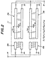
- Fig. 2 is a schematic view showing the structure of a first embodiment of the surface acoustic wave matched filter according to the invention.
- two input side electrodes 12a and 12b and two output side electrodes 13a and 13b are formed on a surface of a piezo-electrical substrate 11.
- the first and second input side electrodes 12a and 12b have the same structure and are connected to an input terminal 14 in parallel with each other.
- the input side electrodes convert a spread spectrum signals supplied to the input terminal 14 into an surface acoustic wave.
- the first output side electrode 13a has a configuration which is similar to that of the second output side electrode 13b.
- a period ⁇ 1 of electrode fingers of the first electrode 13a is different from a period ⁇ 2 of electrode fingers of the second electrode 13b and a tap distance L 1 of the first electrode 13a is different from that L 2 of the second electrode 13b
- a scale of the first output side electrode 13a is different from that of the second output side electrode 13b.
- a carrier frequency f 0 of the spread spectrum signal is 2.500 GHz
- a length N of the PN code is 11 and the PN code is of the Baker code
- the period ⁇ 2 of the electrode fingers of the second output side electrode 13b is 2.4012 ⁇ m and the distance L 1 between taps is 259.3296 ⁇ m.
- the surface acoustic wave matched filter By constructing the surface acoustic wave matched filter in the manner explained above, even if the propagating velocity of the surface acoustic wave varies due to the fact that the temperature of the piezo-electrical substrate 11 varies or respective piezo-electric substrates have different propagating velocities, a demodulated signal strongly correlated with the original base-band signal can be derived from the output terminal 15. Moreover, even if the propagating velocity of the surface acoustic wave locally fluctuates within the piezo-electrical substrate 11, the fluctuation is averaged, and it is also possible to obtain the demodulated signal strongly correlated with the base-band signal.
- Fig. 3 shows a condition in which the demodulated signal is disturbed by the variation in the propagating velocity of the surface acoustic wave due to the temperature variation of the conventional surface acoustic wave matched filter.
- the data is obtained under such a condition that the input side electrode has 64 pairs of electrode fingers and the output side electrode has six pairs of electrode fingers.
- the period ⁇ of the electrode fingers of the output side electrode is set to 2.4 ⁇ m and the tap distance L is set to 108 ⁇ . Therefore, an optimum correlation can be attained for the propagating velocity of the surface acoustic wave 6000 m/sec.
- the graph shows a condition in which the propagating velocity changes to 6000 ⁇ 5 m/sec. The correlation is disturbed largely and the original base-band signal could no more be reproduced reliably.
- Fig. 4 shows the demodulated signal obtained by the surface acoustic wave matched filter according to this invention shown in Fig. 2 under the same condition as that stated above.
- the demodulated signal is obtained in the form of a superimposition of a strongly correlated demodulated signal on the demodulated signal having the correlation strongly disturbed as shown in Fig. 3, but a ideal demodulated signal can be easily derived by an appropriate signal process utilizing a large difference in peak level.
- Fig. 5 shows a second embodiment of the surface acoustic wave matched filter according to the invention.
- the electrode pattern of the present embodiment has an advantage that a mask for photolithography can be easily made. Also in the present embodiment, even if the propagating velocity of the surface acoustic wave varies due to temperature variation or fluctuates for respective substrates or within a single substrate, the demodulated signal having the large component strongly correlated with the original base-band signal can be obtained.
- the demodulated signal is obtained by summing the output signals derived from the two output side electrodes, but according to the invention, an output signal may be selected from a plurality of output signals derived from a plurality of output side electrodes.
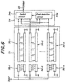
- Fig. 6 shows a third embodiment of the surface acoustic wave matched filter according to the invention, in which an output signal is selected from a plurality of signals derived from a plurality of output side electrodes.
- k input side electrodes 32-1 ⁇ 32-k and k output side electrodes 33-1 ⁇ 33-k are arranged on a piezo-electrical substrate 31 in parallel with each other viewed in the propagating direction of the surface acoustic wave like as the previous embodiments.
- output signals derived from the k output side electrodes 33-1 ⁇ 33-k are supplied to a selection circuit 34 and a single which is most strongly correlated with the original base-band signal is selected, and the thus selected signal is supplied to an output terminal 35 as a demodulated signal.
- the selection circuit 34 compares a peak detection circuit 34a which compares peaks of the signals derived from the k output side electrodes 33-1 ⁇ 33-k with each other and determines an output side electrode which produces the signal having the highest peak, and a switch circuit 34b which extracts the output signal having the highest peak derived from the detected output side electrode.
- the selection of the output signal may be carried out not only by the above explained selection circuit shown in Fig. 6, but the selection of the output signal may be conducted manually. It such a case, the selection circuit may be simply constructed by a analog switch.
- Fig. 7 shows the structure of a fourth embodiment of the surface acoustic wave matched filter according to this invention.
- a single input side electrode 42 and a single output side electrode 43 are provided on a piezo-electrical substrate 41, and electrode fingers of the output side electrode are tilted or inclined by an angle ⁇ with respect to a direction of the aperture length.
- the inclination angle ⁇ is a minimum value, for example 0°, at a center of the output side electrode 43 and increases gradually toward both ends of the output side electrode in opposite directions.
- the above structure is equivalent to a structure in which innumerable output side electrodes having continuously varying tap distances are arranged in parallel with each other viewed in the propagating direction of the surface acoustic wave, and the influence of the variation in the propagating velocity of the surface acoustic wave and the fluctuation in the propagating velocity for respective substrates and within a single substrate can be compensated for, and thus the demodulated signal strongly correlated with the original base-band signal can be obtained.
- Fig. 8 shows the structure of a fifth embodiment of the surface acoustic wave matched filter according to the invention.
- a single input side electrode 52 and a single output side electrode 53 are provided on a piezo-electrical substrate 51, and electrode fingers of the output side electrode are formed like a dog-leg shape viewed in the direction of the aperture length.
- the electrode fingers are formed to be straight, and steps of the dog-leg shape electrode fingers are gradually increased toward both ends of the output side electrodes in opposite directions.
- upper and lower halves of the output side electrode 53 have different design values of the propagating velocity.
- the upper half of the output side electrodes 53 is designed to have a strong correlation at a propagating velocity of 6000 m/sec and the lower half is designed to have a strong correlation at a propagating velocity of 6003 m/sec. Then, also in the present embodiment, the influence of the variation in the propagating velocity of the surface acoustic wave and the fluctuation in the propagating velocity for respective substrates and within a single substrate can be compensated for, and thus the demodulated signal strongly correlated with the original base-band signal can be obtained.
- Fig. 9 shows the structure of a sixth embodiment of the surface acoustic wave matched filter according to the invention.
- a single input side electrode 62 and a single output side electrode 63 are arranged on a piezo-electrical substrate 61, and thin films 64 are provided to cover the surface of the substrate between electrode fingers of the output side electrode such that a covering ratio of a thin film is changed in a direction of the aperture length.
- the propagating velocity of the surface acoustic wave along the surface of the substrate 61 is changed by the thin films 64 formed on the substrate surface, and therefore by changing the covering ratio of the thin films viewed in the direction of the aperture length, it is possible to attain the same operational function as that of the embodiment shown in Fig. 7.
- the covering ratio of the thin films 64 formed between the electrode fingers 63 is changed in the direction of the aperture length, but the thickness of the thin film may be changed in the direction of the aperture length because the propagating velocity of the surface acoustic wave changes also in accordance with a thickness of the thin films.
- the covering ratio of the thin films viewed in the aperture length may be not may be not changed.
- Fig. 10 is a schematic view showing the structure of a seventh embodiment of the surface acoustic wave according to the invention.
- a single input side electrode 72 and a single output side electrode 73 are provided on a surface of a piezo-electrical substrate 71 and recessed portions 74 are formed in the surface of the substrate between electrode fingers of the output side electrode such that a size of the recessed portion viewed in the propagating direction of the surface acoustic wave is changed in the direction of the aperture length.
- the propagating velocity of the surface acoustic wave is changed by the recessed portions 74 formed in the surface of the piezo-electrical substrate 61, a similar operation function to that of the embodiment illustrated in Fig. 8 can be attained by changing a size of the recessed portions viewed in the direction of the aperture length.
- a depth of the recessed portions 74 may be changed viewed in the direction of the aperture length.
- a combined signal may be supplied to a simple limiter circuit to detect a signal having the highest peak.
- a plurality of the input side electrodes and output side electrodes may be arranged in parallel with each other in the propagating direction of the surface acoustic wave.
- the dog-leg shaped output side electrode may have plural steps.
- the size and thickness of the thin films and the size and depth of the recessed portions may be changed in a stepwise manner instead of continuously.
- the output side electrodes have parts having different delay times between taps, the decrease in the correlation of the demodulated signal with the original base-band signal owing to the variation in the propagating velocity of the surface acoustic wave due to the temperature characteristic and the fluctuation in the propagating velocity for respective substrates or within a single substrate can be avoided.
- the present invention has an advantage that a delay element having the temperature characteristic and a complex circuit of large power consumption are not required.
Landscapes
- Physics & Mathematics (AREA)
- Acoustics & Sound (AREA)
- Surface Acoustic Wave Elements And Circuit Networks Thereof (AREA)
Applications Claiming Priority (3)
| Application Number | Priority Date | Filing Date | Title |
|---|---|---|---|
| JP10922697A JP3338628B2 (ja) | 1997-04-25 | 1997-04-25 | 弾性表面波マッチトフィルタ |
| JP109226/97 | 1997-04-25 | ||
| PCT/JP1998/001897 WO1998049774A1 (fr) | 1997-04-25 | 1998-04-24 | Filtre adapte a ondes acoustiques de surface |
Publications (2)
| Publication Number | Publication Date |
|---|---|
| EP0915564A1 true EP0915564A1 (fr) | 1999-05-12 |
| EP0915564A4 EP0915564A4 (fr) | 2004-12-08 |
Family
ID=14504812
Family Applications (1)
| Application Number | Title | Priority Date | Filing Date |
|---|---|---|---|
| EP98917671A Withdrawn EP0915564A4 (fr) | 1997-04-25 | 1998-04-24 | Filtre adapte a ondes acoustiques de surface |
Country Status (4)
| Country | Link |
|---|---|
| US (1) | US6229409B1 (fr) |
| EP (1) | EP0915564A4 (fr) |
| JP (1) | JP3338628B2 (fr) |
| WO (1) | WO1998049774A1 (fr) |
Cited By (1)
| Publication number | Priority date | Publication date | Assignee | Title |
|---|---|---|---|---|
| EP0973257A3 (fr) * | 1998-07-16 | 2001-01-24 | Ngk Insulators, Ltd. | Filtre adapté aux ondes acoustiques de surface |
Families Citing this family (3)
| Publication number | Priority date | Publication date | Assignee | Title |
|---|---|---|---|---|
| US20040105485A1 (en) * | 2002-07-29 | 2004-06-03 | Unaxis Usa, Inc. | Temperature compensation for acousto-optc devices |
| JP4654271B2 (ja) | 2008-06-25 | 2011-03-16 | 日本電波工業株式会社 | トランスバーサル型フィルタ |
| US12562714B2 (en) * | 2021-10-05 | 2026-02-24 | Skyworks Solutions, Inc. | Transversal lamb wave filter with improved out of band rejection |
Family Cites Families (18)
| Publication number | Priority date | Publication date | Assignee | Title |
|---|---|---|---|---|
| JPS4953746A (fr) * | 1972-09-27 | 1974-05-24 | ||
| GB1481419A (en) * | 1974-02-15 | 1977-07-27 | Gen Electric Co Ltd | Phase shift demodulators |
| JPS50155155A (fr) * | 1974-06-04 | 1975-12-15 | ||
| JPS583619B2 (ja) * | 1975-09-29 | 1983-01-22 | 日本電信電話株式会社 | シンゴウパルスハレツサイセイカイロ |
| US4097825A (en) * | 1977-01-05 | 1978-06-27 | Hughes Aircraft Company | Surface acoustic wave tapped delay line |
| DE3121516A1 (de) * | 1981-05-29 | 1983-01-05 | Siemens AG, 1000 Berlin und 8000 München | Pulskompressionsfilter nach art einer dispersiven verzoegerungsleitung |
| JPS59163578A (ja) * | 1983-03-09 | 1984-09-14 | Mitsubishi Electric Corp | パルス圧縮装置 |
| US4625207A (en) * | 1983-06-30 | 1986-11-25 | X-Cyte Inc. | Surface acoustic wave passive transponder having amplitude and phase-modifying surface pads |
| JPS621309A (ja) * | 1985-06-27 | 1987-01-07 | Clarion Co Ltd | 弾性表面波装置 |
| JP2890195B2 (ja) * | 1987-11-06 | 1999-05-10 | 和彦 山之内 | 弾性表面波マッチドフィルタの温度補償方法 |
| JP2733774B2 (ja) | 1988-11-14 | 1998-03-30 | 国際電気株式会社 | 弾性表面波マッチドフィルタを用いた受信復調回路 |
| JPH0417409A (ja) * | 1990-05-11 | 1992-01-22 | Sony Corp | 表面弾性波タップ付き遅延線装置 |
| JPH07193478A (ja) | 1993-12-24 | 1995-07-28 | Showa Electric Wire & Cable Co Ltd | 弾性表面波マッチドフィルタ装置 |
| JP2659903B2 (ja) * | 1994-01-31 | 1997-09-30 | 日本無線株式会社 | Sawスペクトル拡散復調器 |
| JP2842989B2 (ja) * | 1994-03-22 | 1999-01-06 | 日本無線株式会社 | Sawスペクトル拡散復調器及びその構成方法 |
| JPH0888535A (ja) | 1994-09-14 | 1996-04-02 | Showa Electric Wire & Cable Co Ltd | 弾性表面波マッチドフィルタ |
| JP3424453B2 (ja) * | 1996-08-09 | 2003-07-07 | 松下電器産業株式会社 | スペクトラム拡散通信装置 |
| JPH1127091A (ja) * | 1997-07-02 | 1999-01-29 | Hitachi Media Electron:Kk | 非同期型弾性表面波マッチドフィルタ |
-
1997
- 1997-04-25 JP JP10922697A patent/JP3338628B2/ja not_active Expired - Fee Related
-
1998
- 1998-04-24 EP EP98917671A patent/EP0915564A4/fr not_active Withdrawn
- 1998-04-24 US US09/203,000 patent/US6229409B1/en not_active Expired - Fee Related
- 1998-04-24 WO PCT/JP1998/001897 patent/WO1998049774A1/fr not_active Ceased
Cited By (2)
| Publication number | Priority date | Publication date | Assignee | Title |
|---|---|---|---|---|
| EP0973257A3 (fr) * | 1998-07-16 | 2001-01-24 | Ngk Insulators, Ltd. | Filtre adapté aux ondes acoustiques de surface |
| US6275123B1 (en) | 1998-07-16 | 2001-08-14 | Ngk Insulators, Ltd. | Surface acoustic wave matched filter with dispersive substrate and saw group velocity based output electrode design |
Also Published As
| Publication number | Publication date |
|---|---|
| JPH10303692A (ja) | 1998-11-13 |
| EP0915564A4 (fr) | 2004-12-08 |
| US6229409B1 (en) | 2001-05-08 |
| JP3338628B2 (ja) | 2002-10-28 |
| WO1998049774A1 (fr) | 1998-11-05 |
Similar Documents
| Publication | Publication Date | Title |
|---|---|---|
| US8462136B2 (en) | Pointer detection apparatus and pointer detection method | |
| EP0700156A2 (fr) | Dispositif pour former des faisceaux utilisant des filtres adaptatifes à coefficients limités pour détection de signaux parasites | |
| Adhikari et al. | Extending coprime sensor arrays to achieve the peak side lobe height of a full uniform linear array | |
| US5923388A (en) | Touch panel | |
| EP0802699A2 (fr) | Méthode pour éligir électroniquement la distance entre deux transducteurs acoustiques/électroniques et un appareil de prothèse auditive | |
| Neiman et al. | Linear response theory applied to stochastic resonance in models of ensembles of oscillators | |
| EP0621737B1 (fr) | Appareil microphonique stéreo ultradirectionnel | |
| EP0915564A1 (fr) | Filtre adapte a ondes acoustiques de surface | |
| US20040246076A1 (en) | Surface acoustic wave arrangement for broadband signal transmission | |
| US6766029B1 (en) | Method for electronically selecting the dependency of an output signal from the spatial angle of acoustic signal impingement and hearing aid apparatus | |
| JPS6194411A (ja) | 帯域可変弾性表面波フイルタ | |
| JP3712035B2 (ja) | 表面波装置の製造方法 | |
| CA2034392A1 (fr) | Electrode a vitesse constante et a reflectivite predeterminee | |
| US6275123B1 (en) | Surface acoustic wave matched filter with dispersive substrate and saw group velocity based output electrode design | |
| US4210883A (en) | Technique for widening the temperature range of surface acoustic wave reflection array filters | |
| CN101622758B (zh) | 通信装置的天线配置方法及安装装置、天线装置 | |
| CA2134275C (fr) | Interferometrie a suppression de la multiplicite des trajets | |
| EP0577089B1 (fr) | Dispositif à ondes acoustiques de surface, démodulateur et système de communication utilisant ce dispositif à ondes de surface | |
| US7558352B2 (en) | Apparatus and method for preprocessing of pilot symbols for channel estimation by means of adaptive low-pass filtering | |
| US7885991B2 (en) | Digital filter having a fir filter and a warped fir filter, and a listening device including such a digital filter | |
| Bentkus | An inequality for large deviation probabilities of sums of bounded iid random variables | |
| EP0484689A1 (fr) | Dispositif à ondes acoustiques de surface avec suppression des ondes refléchies sur les bords des guides d'ondes et système de communication l'utilisant | |
| JP2586391B2 (ja) | ビームフォーミング用係数生成方法および装置 | |
| US4191933A (en) | Differential mixing surface acoustic wave signal processor | |
| RU2573787C1 (ru) | Многолучевая адаптивная антенная решетка |
Legal Events
| Date | Code | Title | Description |
|---|---|---|---|
| PUAI | Public reference made under article 153(3) epc to a published international application that has entered the european phase |
Free format text: ORIGINAL CODE: 0009012 |
|
| 17P | Request for examination filed |
Effective date: 19990118 |
|
| AK | Designated contracting states |
Kind code of ref document: A1 Designated state(s): DE FR GB |
|
| A4 | Supplementary search report drawn up and despatched |
Effective date: 20041022 |
|
| RIC1 | Information provided on ipc code assigned before grant |
Ipc: 7G 01S 13/02 B Ipc: 7H 03H 9/64 B Ipc: 7H 03H 9/44 B Ipc: 7H 03H 9/42 A |
|
| 17Q | First examination report despatched |
Effective date: 20050415 |
|
| STAA | Information on the status of an ep patent application or granted ep patent |
Free format text: STATUS: THE APPLICATION IS DEEMED TO BE WITHDRAWN |
|
| 18D | Application deemed to be withdrawn |
Effective date: 20050826 |